
And its begun... Cam & Supercharger
 08-10-2012, 02:43 AM
#1
Drifting

Thread Starter


So after collecting parts since last March I finally took the first steps today in tearing into my 2005 Corvette. I was a little nervous as this is my pride and joy, but very excited as well. I have never taken on a project of this magnitude, but my plan is to work slowly, take detailed pictures, which I will also share with all of you, and hopefully get this all done and tuned by mid September. As I have mentioned I have decided to post the steps I take online; I have a duel purpose for doing this. For one it would be nice to inspire other novice installers to jump in and get their hands dirty. These projects usually leave me cursing and swearing but when its all done, running, and you are able to take credit for the majority of the work yourself the feeling of pride and accomplishment is unmatched. My second reason for posting... lots of great members and information on this site. As I had mentioned I consider myself a hobbyist and as such am hoping some of the pro's and old timers here on this board will point me in the right direction if I begin to stray.
So here goes....
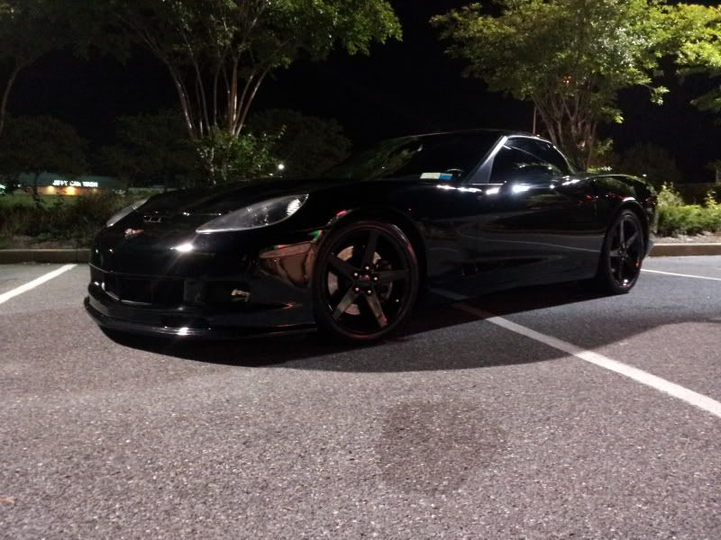
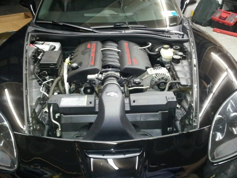
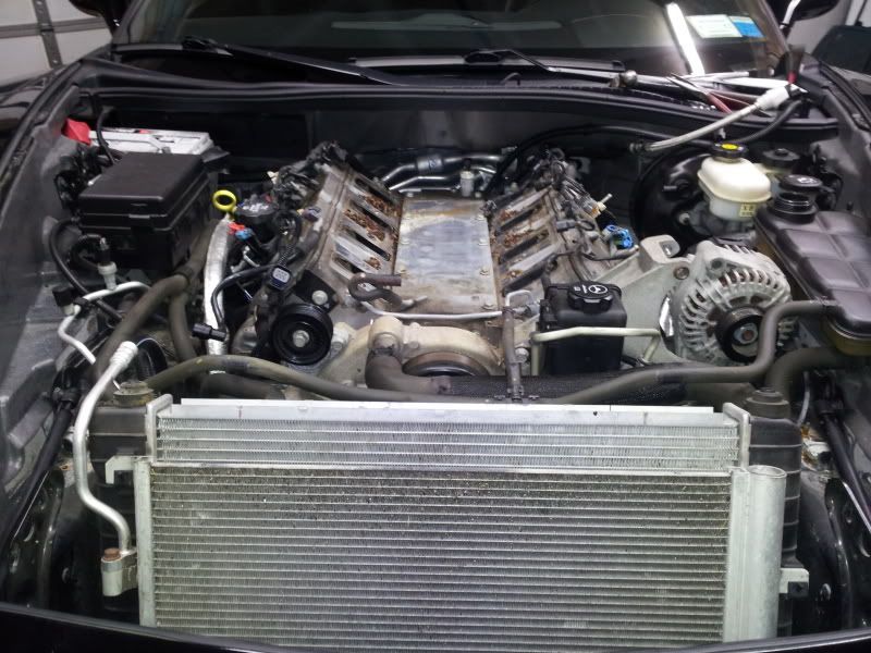
Ok I have a 2005 LS2 Corvette Z51 with a 6 Speed Manual. Performance wise everything on the car is currently stock with the exception of a magnaflow cat back and a crappy vararam.
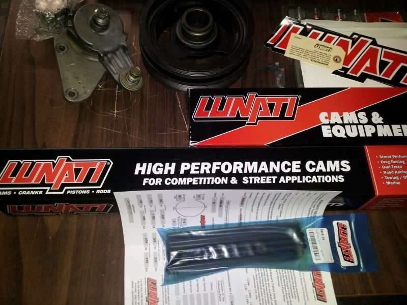
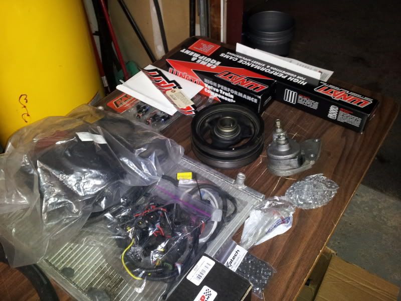
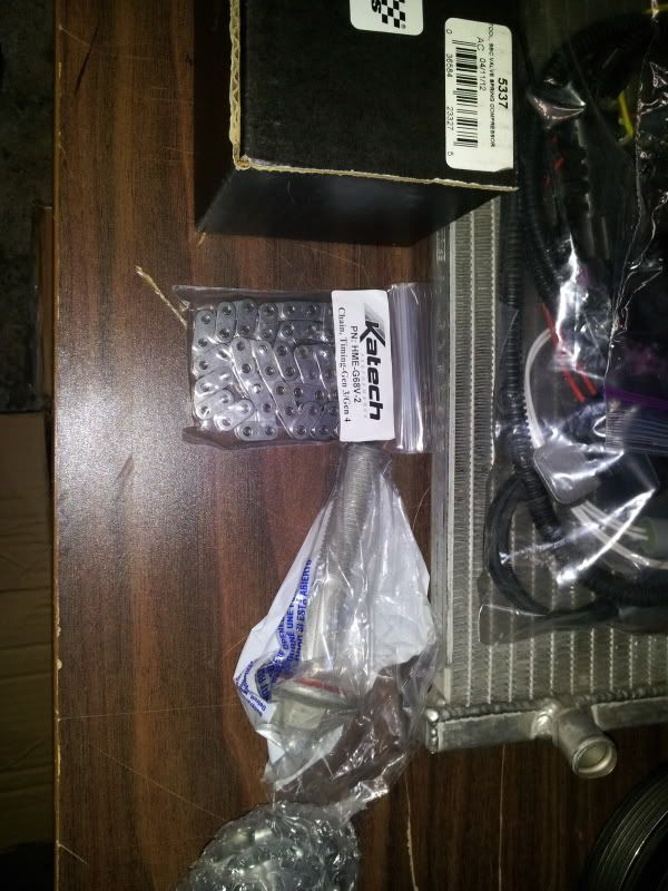
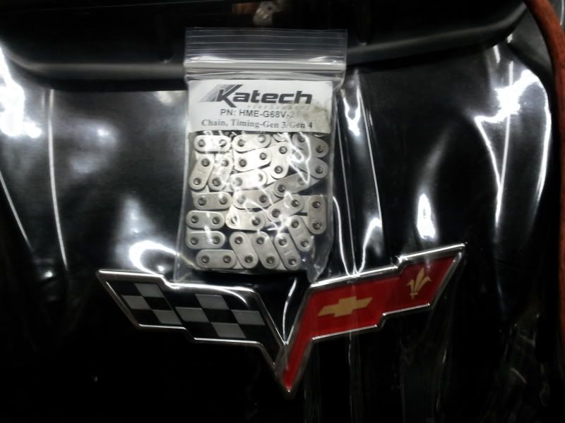
I will be installing a Magnuson M112 Supercharger with a 1:1 rear ratio and a 3.0 pulley on the front. When I purchased the Supercharger back in April my goal was to just install it, and be done with it. Some where along the way I got lost. It seems like every time you buy just one more part there are 3 more you feel compliment the setup as well and need to be bought; which leads me to the Hendrix Engineering Custom Blower Cam, built by Lunati Cams, Double valve springs, new push rods, keepers, and valve seals. I picked up a Katech C5R timing chain, Innovators West 8 rib overdrive pulley for better belt wrap, and just today purchased an ECS tensioner so their is no chance thing thing will slip. With all this extra boost and the bigger cam, this thing is choking so I picked up a set of Kooks 1 7/8 headers with 3in X-pipe which is not catted. Now it needed more fuel so I purchased a set of FAST 65lb injectors. The only three things I am still hunting for is a fuel pump, and potentially a Nick Williams Throttle Body, and a Lingenfelter MAF.
Got a little bit done today. My next day off is Tuesday and my goal is to hit this thing hard.... Here are some pictures:
The car,
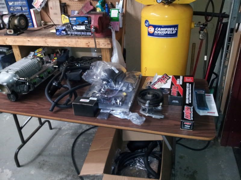
The parts,
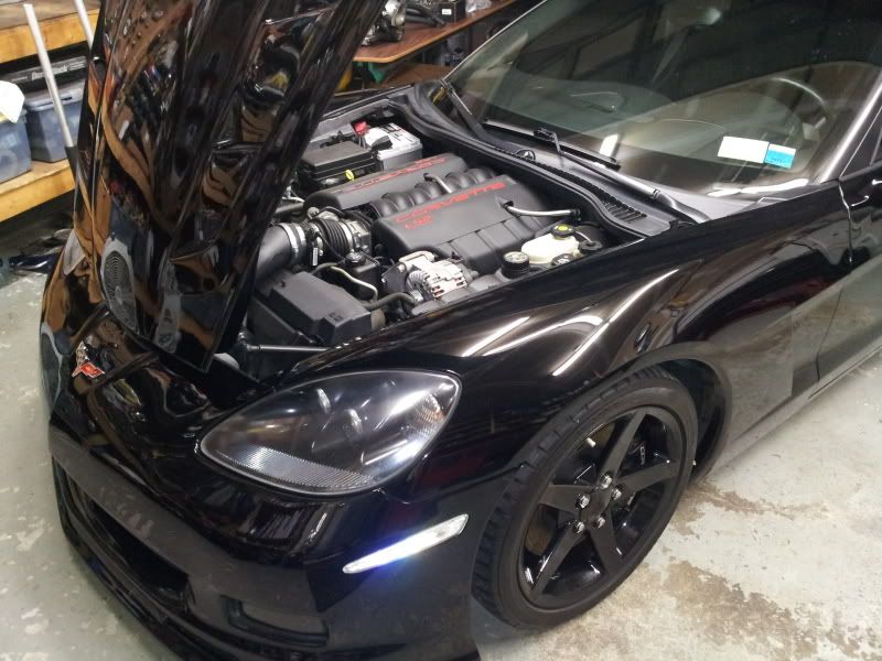
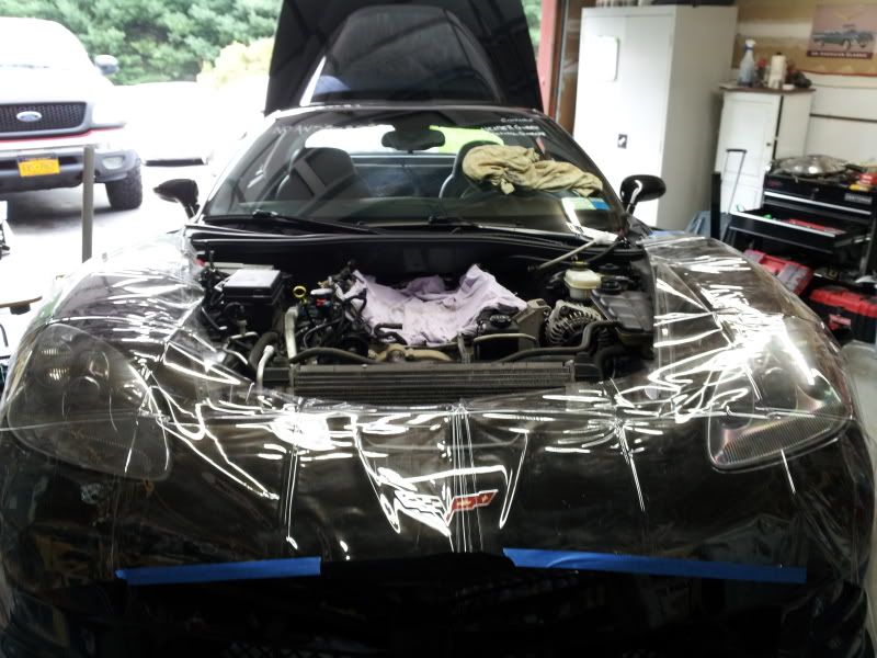
And the deconstruction begins.....
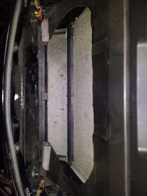
This is what I am talking about when I mentioned I have a crappy Vararam. It pretty much blew the gasket out and fell apart. Fortunately the filter is jammed in the upper part of the assembly so even though it fell apart, the air coming in over the last 3K miles was still filtered.
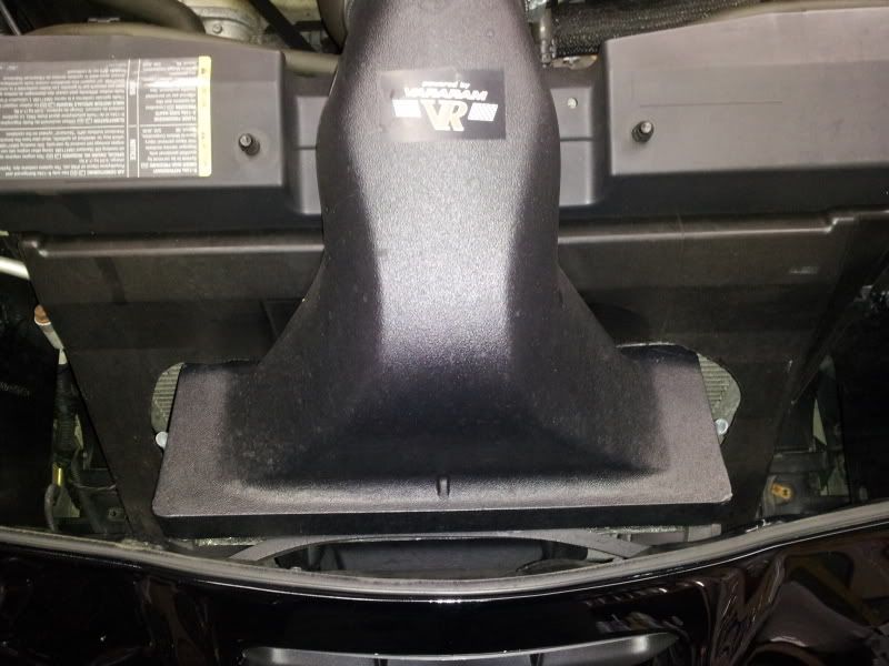
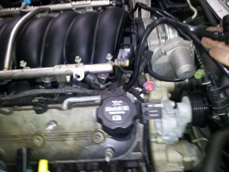
Vararam Out... making space.....
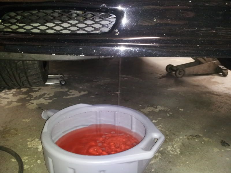
Removing Coolant
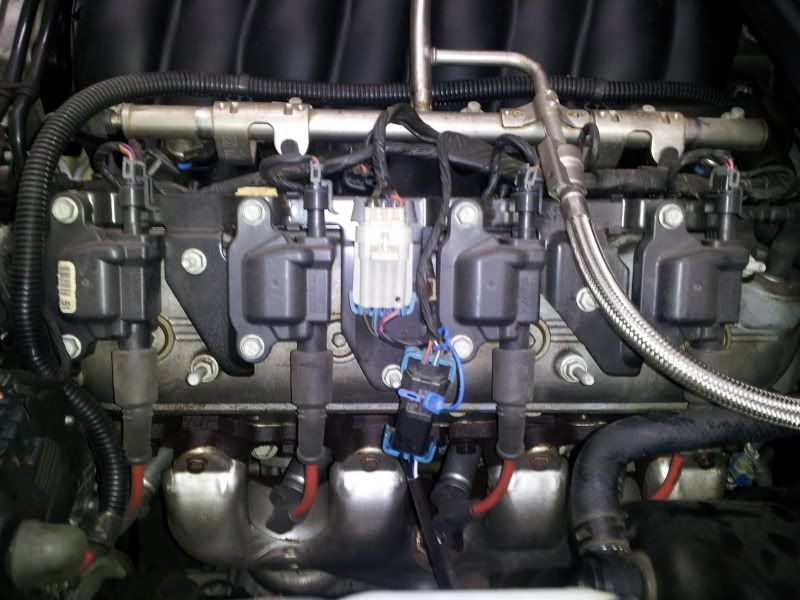
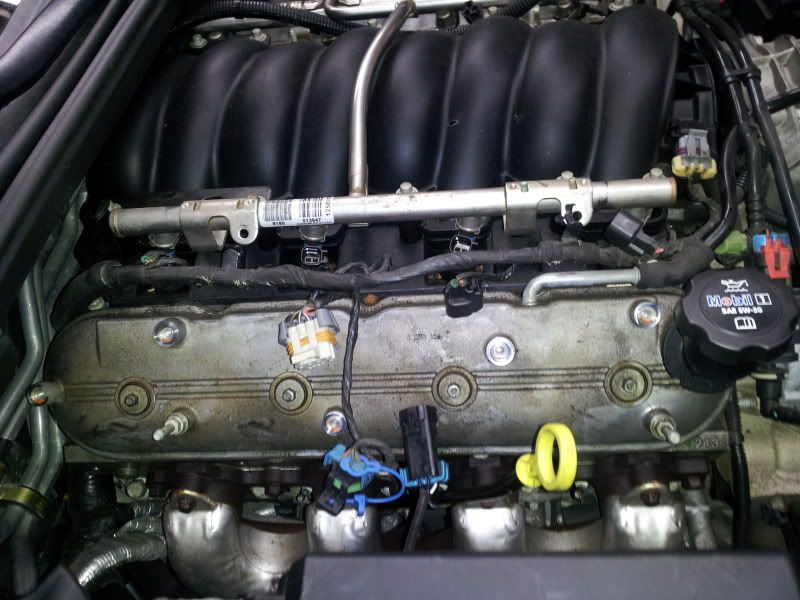
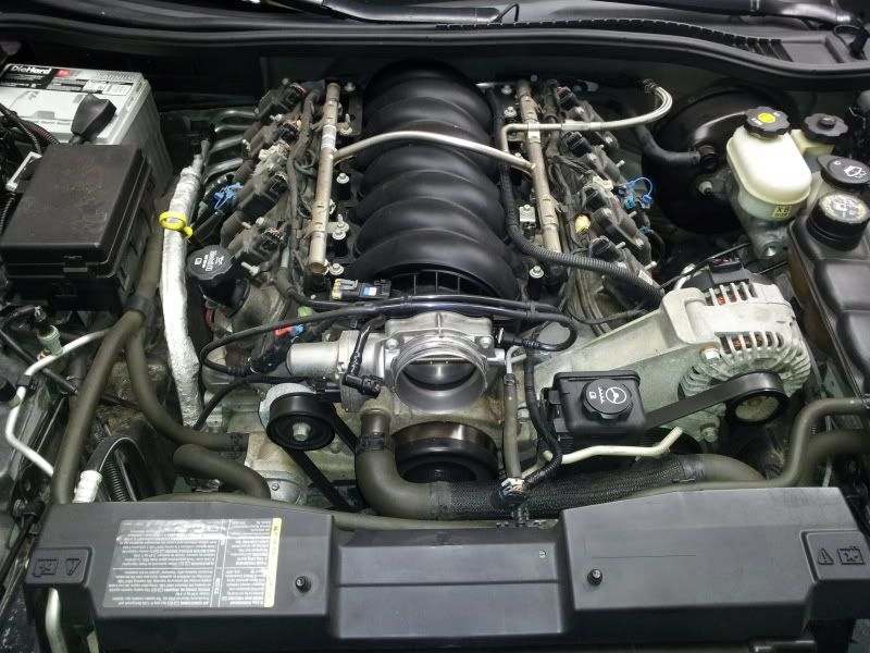
Carefully removing harnesses from intake manifold area
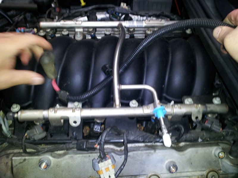
Removing Intake bolts and getting ready to pull intake
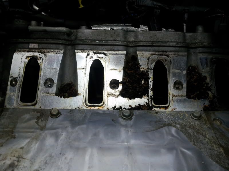
Removing Mice........
2-2.5 Hours.... this is my first time.... I am satisfied so far. More to come on Tuesday.
DG
So here goes....
Ok I have a 2005 LS2 Corvette Z51 with a 6 Speed Manual. Performance wise everything on the car is currently stock with the exception of a magnaflow cat back and a crappy vararam.
I will be installing a Magnuson M112 Supercharger with a 1:1 rear ratio and a 3.0 pulley on the front. When I purchased the Supercharger back in April my goal was to just install it, and be done with it. Some where along the way I got lost. It seems like every time you buy just one more part there are 3 more you feel compliment the setup as well and need to be bought; which leads me to the Hendrix Engineering Custom Blower Cam, built by Lunati Cams, Double valve springs, new push rods, keepers, and valve seals. I picked up a Katech C5R timing chain, Innovators West 8 rib overdrive pulley for better belt wrap, and just today purchased an ECS tensioner so their is no chance thing thing will slip. With all this extra boost and the bigger cam, this thing is choking so I picked up a set of Kooks 1 7/8 headers with 3in X-pipe which is not catted. Now it needed more fuel so I purchased a set of FAST 65lb injectors. The only three things I am still hunting for is a fuel pump, and potentially a Nick Williams Throttle Body, and a Lingenfelter MAF.
Got a little bit done today. My next day off is Tuesday and my goal is to hit this thing hard.... Here are some pictures:
The car,
The parts,
And the deconstruction begins.....
This is what I am talking about when I mentioned I have a crappy Vararam. It pretty much blew the gasket out and fell apart. Fortunately the filter is jammed in the upper part of the assembly so even though it fell apart, the air coming in over the last 3K miles was still filtered.
Vararam Out... making space.....
Removing Coolant
Carefully removing harnesses from intake manifold area
Removing Intake bolts and getting ready to pull intake
Removing Mice........
2-2.5 Hours.... this is my first time.... I am satisfied so far. More to come on Tuesday.
DG
 08-10-2012, 03:00 AM
#2
Drifting
Thread Starter
My first question, does anyone have a trick for moving the condenser out of the way, or do I need to drain the A/C system and remove it?
Also, if I unbolt the cradle with that give me the room I need to install the cam as well as pin the crank, or does that method only work for pinning the crank? Trying to avoid taking the rack out.
DG
Also, if I unbolt the cradle with that give me the room I need to install the cam as well as pin the crank, or does that method only work for pinning the crank? Trying to avoid taking the rack out.
DG
08-10-2012, 08:31 AM
#3
Former Vendor

Dan:
The AC Condenser is attached to the radiator and the it slides into 4 clips. The one on the lower right corner is PITA to separate. Lately, I have been removing the radiator and AC condenser together. I also drop the front cradle and it is faster/easier. Just pitch the cradle far enough down to get the balancer off. This is an excellent time to replace the motor mounts. The Hinson Supercar Mount work great.
The AC Condenser is attached to the radiator and the it slides into 4 clips. The one on the lower right corner is PITA to separate. Lately, I have been removing the radiator and AC condenser together. I also drop the front cradle and it is faster/easier. Just pitch the cradle far enough down to get the balancer off. This is an excellent time to replace the motor mounts. The Hinson Supercar Mount work great.
Last edited by Brian@RPT; 08-10-2012 at 10:01 AM.
08-10-2012, 10:00 AM
#4
Drifting
Dan
The A/C condenser will lift up and away from the radiator. When I did my cam change I seperated the radiator and condenser and then just removed the radiator and fan assembly as a unit and hung the condenser up out of the way. I also removed the steering rack off through the passenger side instead of droping the cradle. Did not have to get it realigned or have the A/C system serviced by doing it that way. Make sure to lower the windows and disconnect the battery!! By putting the windows down you can reach in an use the manual door open pulls to get into the car.....
Here is a link to my cam install....... click here
Oh and put some covers over the fenders!!! I used some old bed sheets and some old towels!!!!!
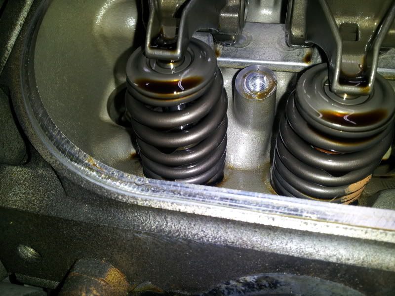
By the way... how did all of that crap get between the heads and the intake and the intake and the valley cover???
Mark
The A/C condenser will lift up and away from the radiator. When I did my cam change I seperated the radiator and condenser and then just removed the radiator and fan assembly as a unit and hung the condenser up out of the way. I also removed the steering rack off through the passenger side instead of droping the cradle. Did not have to get it realigned or have the A/C system serviced by doing it that way. Make sure to lower the windows and disconnect the battery!! By putting the windows down you can reach in an use the manual door open pulls to get into the car.....
Here is a link to my cam install....... click here
Oh and put some covers over the fenders!!! I used some old bed sheets and some old towels!!!!!
By the way... how did all of that crap get between the heads and the intake and the intake and the valley cover???
Mark
Last edited by 08VRZ06; 08-10-2012 at 02:36 PM.
08-15-2012, 06:11 AM
#5
Drifting
Thread Starter
I was able to get some more progress done today. My day began at around 4pm and ended at around 2am in the morning. I started by heading out to Walmart this morning to pickup a vinyl couch cover to protect my fenders. Taped it down and then threw a coupe fender covers over the fenders to sit my tools on. This worked like a charm and protected my fenders and bumper from the power steering fluid that wound up spraying all over my engine bay later in the day.
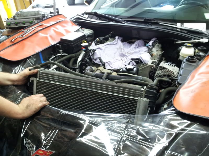
Next thing I decided I was going to do was to pull the radiator. A couple of you had mentioned that I did not have to remove the Condenser, but didn't want to deal with it hanging around in the engine bay and thought it would be easier to pull the whole radiator, fan, and condenser as one unit.... AND IT WAS. So I drained the A/C system, radiator and pulled it
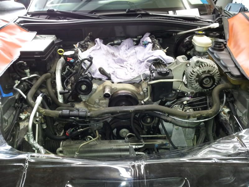
Moved on to removing a few of the accessories... power steering reservoir first, then the water pump... very easy.
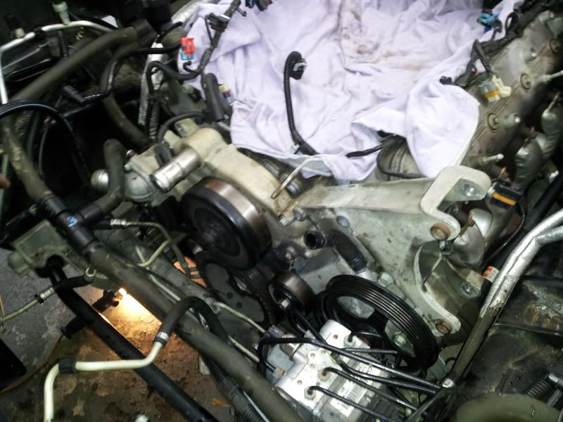
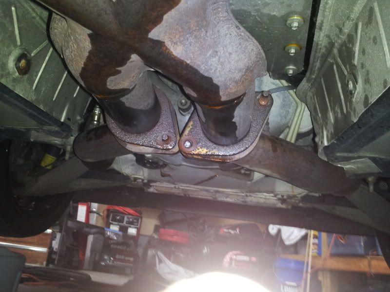
I thought it would be good to remove the exhaust manifolds as well to make room for the Kooks Headers and to make it easier to get the plugs out
Car began fighting back.... that's not paint.
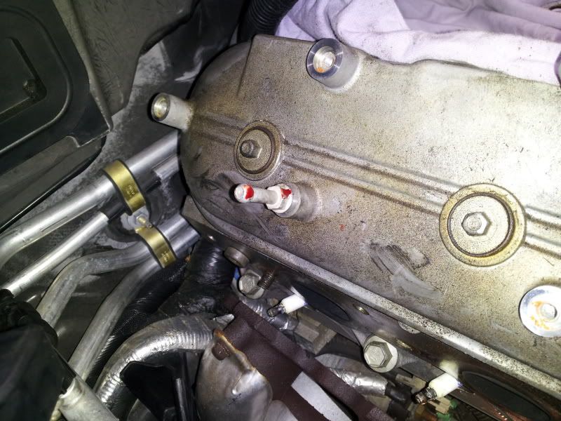
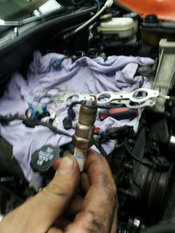
Plugs are white but when I rub them off they look new! 40K on the car.
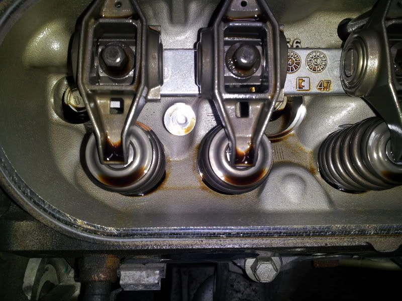
Valve Covers Coming off next
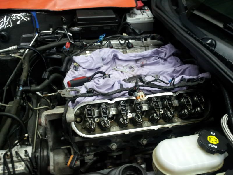
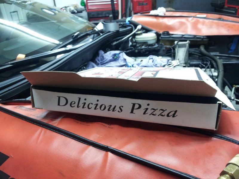
The next step is VERY IMPORTANT! By 8pm at night you are very hungry. Its a good idea to order a delicious pizza.
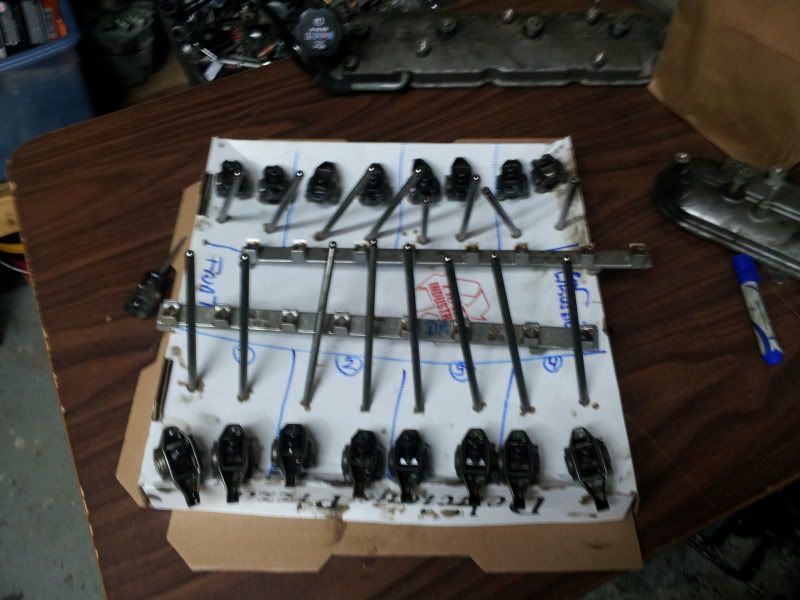
Then use the box to lay out your rocker arms and push rods.
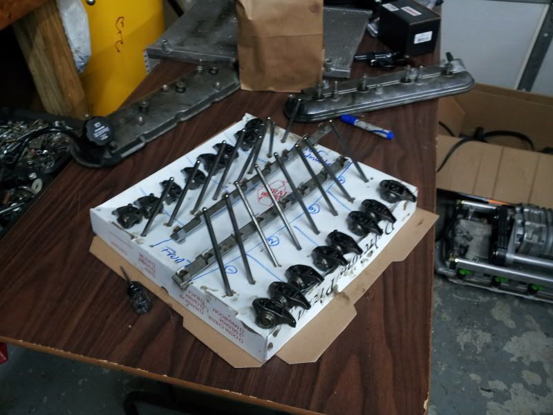
This is a great tool!
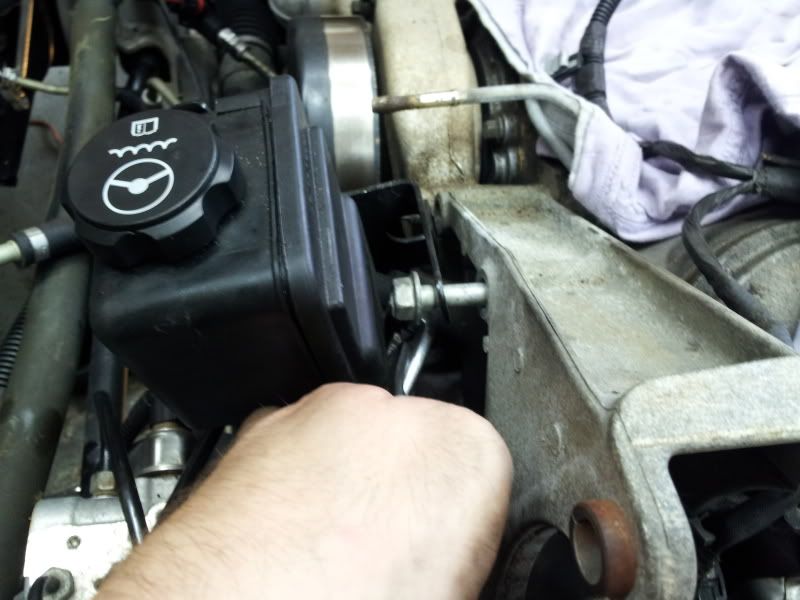
The next thing I did was proceed to waste 45 minutes. Following the Magnuson manual I decided to loosen the sub frame bolts, and use shims to drop the subframe. Then I removed the motor mounts and raised the motor. This gave me PLENTY of room to remove the harmonic balancer pulley bolt, however did NOT give me enough room to remove the pulley itself. Ultimately I was forced to remove the rack which was a B**** to do! But I got it done. For those of you only running a supercharger and need to pin the crank, this is a quick and easy way to make the clearances required to pin the crank, however if you need to remove the pulley itself, THIS WILL NOT WORK, YOU MUST REMOVE THE STEERING RACK!
Anyway these are pictures of the Subframe bolts being loosened and using wooden shims to drop the cradle.
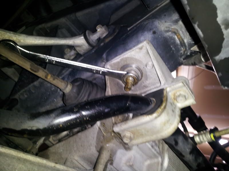
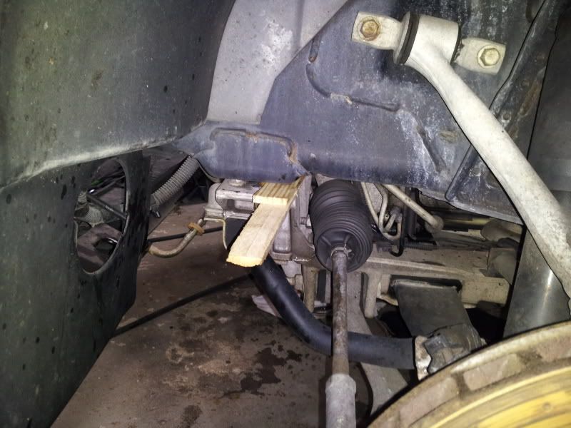
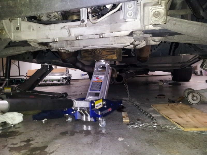
CLEARANCE YOU NEED TO PIN THE CRANK WITHOUT REMOVING THE RACK
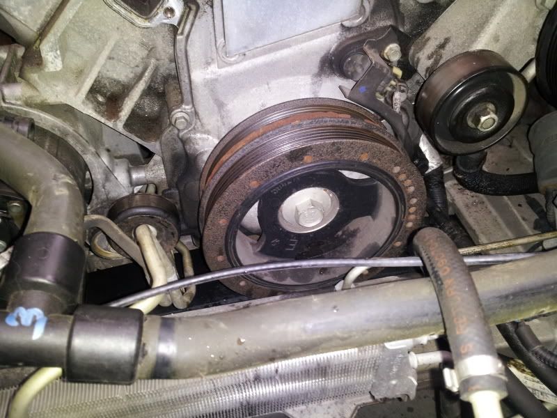
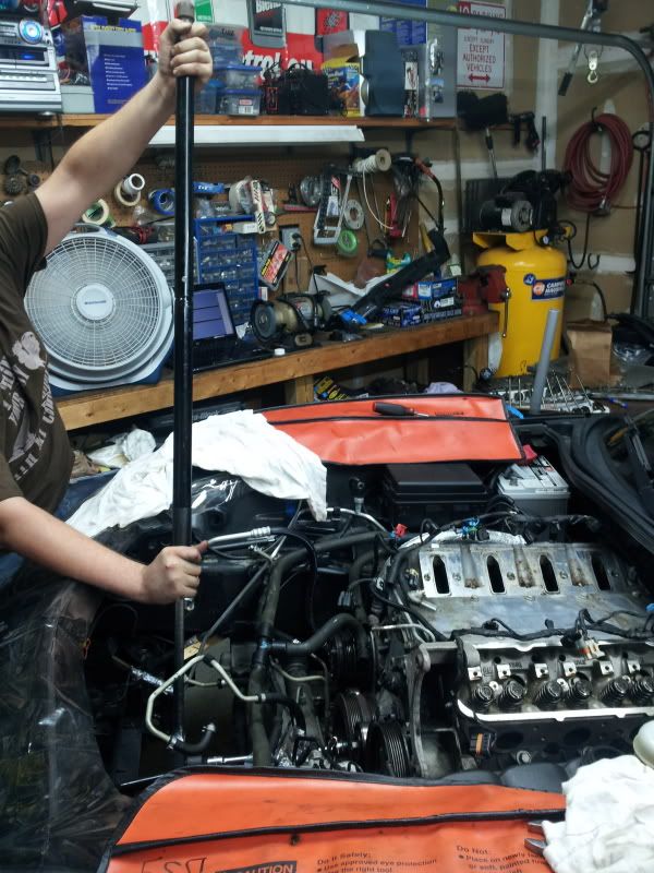
Now get your big mother f****** breaker bar out and break the harmonic balancer bolt free. This took two of us and that bar to remove it. To lock the engine I put the car in 4th gear, and pulled the emergency brake. I am still trying to figure out how I am going to torque this thing to spec????????
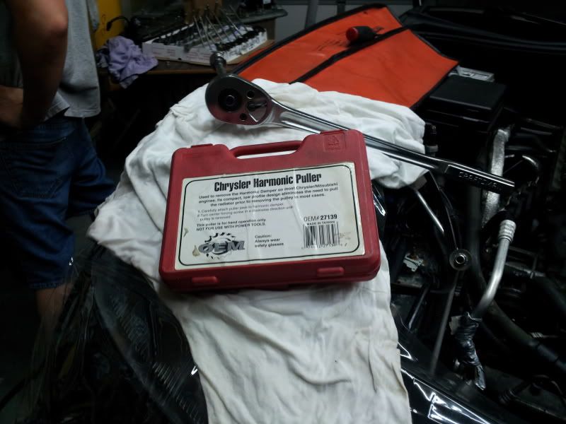
I rented a Chrysler Harmonic Balancer Puller tool from Autozone; worked like a charm.
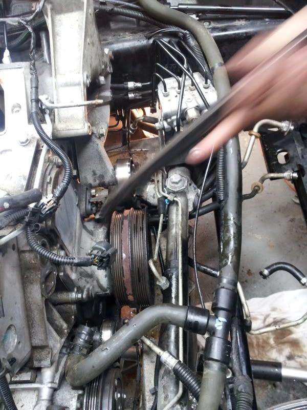
Began pulling the pulley off, and then ran into the clearance issue I described above with the rack, and was forced to spend an hour moving that out of the way.
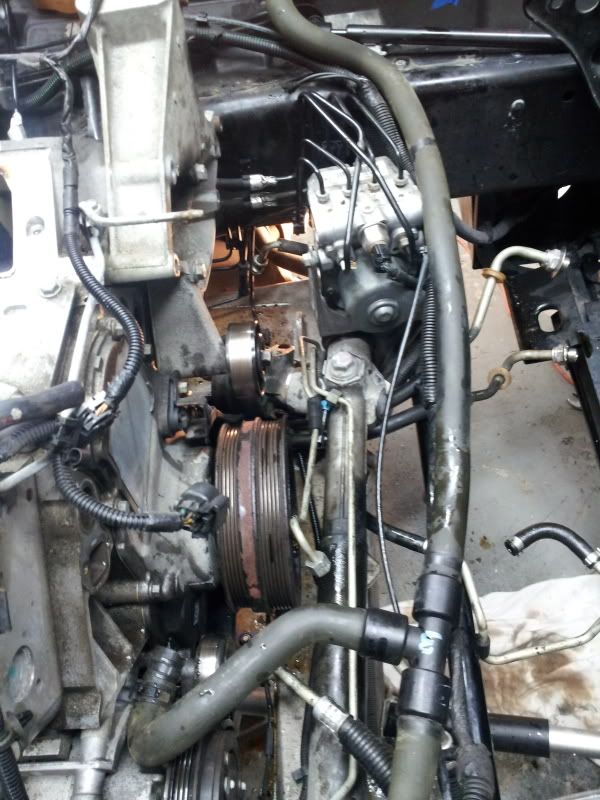
A little finagling and its off
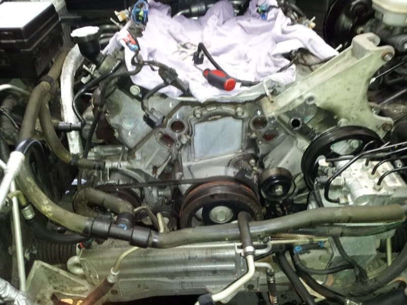
Pulled the timing cover
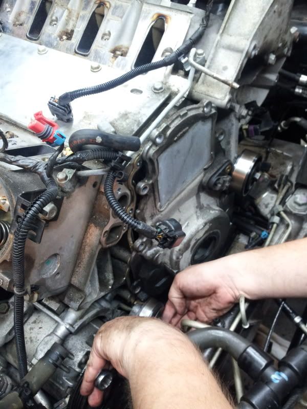
And there it is
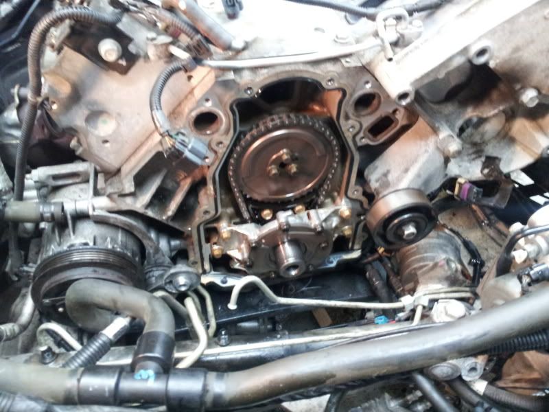
Decided prior to removing the oil pump, timing chain, and cam to line the cam up by eye dot to dot.
Next thing I decided I was going to do was to pull the radiator. A couple of you had mentioned that I did not have to remove the Condenser, but didn't want to deal with it hanging around in the engine bay and thought it would be easier to pull the whole radiator, fan, and condenser as one unit.... AND IT WAS. So I drained the A/C system, radiator and pulled it
Moved on to removing a few of the accessories... power steering reservoir first, then the water pump... very easy.
I thought it would be good to remove the exhaust manifolds as well to make room for the Kooks Headers and to make it easier to get the plugs out
Car began fighting back.... that's not paint.
Plugs are white but when I rub them off they look new! 40K on the car.
Valve Covers Coming off next
The next step is VERY IMPORTANT! By 8pm at night you are very hungry. Its a good idea to order a delicious pizza.
Then use the box to lay out your rocker arms and push rods.
This is a great tool!
The next thing I did was proceed to waste 45 minutes. Following the Magnuson manual I decided to loosen the sub frame bolts, and use shims to drop the subframe. Then I removed the motor mounts and raised the motor. This gave me PLENTY of room to remove the harmonic balancer pulley bolt, however did NOT give me enough room to remove the pulley itself. Ultimately I was forced to remove the rack which was a B**** to do! But I got it done. For those of you only running a supercharger and need to pin the crank, this is a quick and easy way to make the clearances required to pin the crank, however if you need to remove the pulley itself, THIS WILL NOT WORK, YOU MUST REMOVE THE STEERING RACK!
Anyway these are pictures of the Subframe bolts being loosened and using wooden shims to drop the cradle.
CLEARANCE YOU NEED TO PIN THE CRANK WITHOUT REMOVING THE RACK
Now get your big mother f****** breaker bar out and break the harmonic balancer bolt free. This took two of us and that bar to remove it. To lock the engine I put the car in 4th gear, and pulled the emergency brake. I am still trying to figure out how I am going to torque this thing to spec????????
I rented a Chrysler Harmonic Balancer Puller tool from Autozone; worked like a charm.
Began pulling the pulley off, and then ran into the clearance issue I described above with the rack, and was forced to spend an hour moving that out of the way.
A little finagling and its off
Pulled the timing cover
And there it is
Decided prior to removing the oil pump, timing chain, and cam to line the cam up by eye dot to dot.
Last edited by Danspeed1; 08-15-2012 at 06:42 AM.
08-15-2012, 06:34 AM
#6
Drifting
Thread Starter
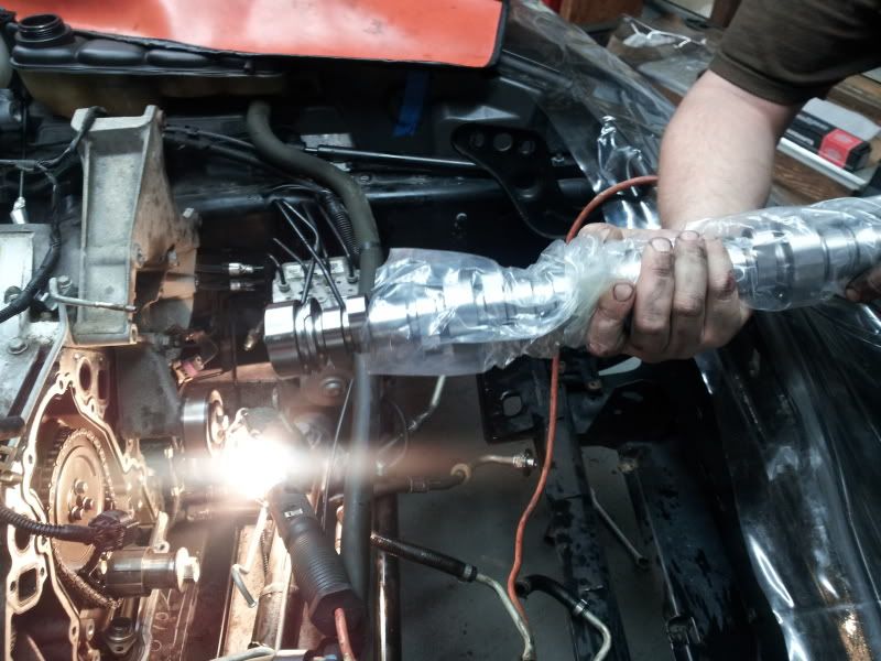
There's the new one! Designed by Hendrix Engineering and built by Lunati Cams, .625 lift at the valve with a 1.7in roller rocker. 114LSA designed specifically to work with the Magnuson M112, supposedly

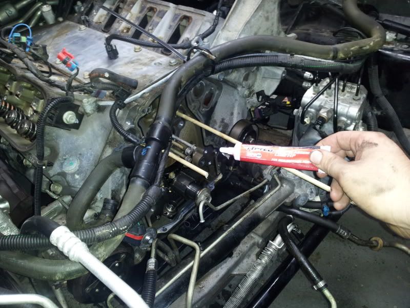
And this is the lube I covered my shaft with before I slid it in.
The next couple of parts went smoothly. So smoothly I am feeling a little lack of confidence. One thing I am misunderstand/concerned about is when I removed the oil pump. I have been told time and time again the oil pump has a special "O-ring" on it and if it is damaged or installed incorrectly, it won't allow oil pressure to build. When I removed the oil pump I removed the four bolts holding it to the engine, the I removed the one bolt holding the pickup on. There appears to be NO o-ring to be found, on the pickup or in the pump hole???? I don't understand. The second surprise was that I didn't expect the cam to come out as easy as it did. I removed the cam plate spun the cam, inserted 5/16's wood dowels into the engine to hold the lifters up and proceeded to remove the original cam. It is in my nature that I tend to like to worry about things I can't see or are unsure off. When I pulled on the cam out first it did not come out. I exerted a little more force and it broke free and came flying out, and wound up making a loud ding noise while inside the engine. I was concerned from the get go about nicking a bearing??? Whats the chances?? How careful do you actually have to be?? Finally after installing the new cam which went in nice and smooth, I found myself concerned about the lack of tension on the C5R timing chain. My buddy who was helping me has a G8 which recently had a new timing chain and factory cam installed. He did not do the work, but was able to see the timing chain when it was installed and says it was exactly the same tension wise. Finally, cam sprocket, chain, and crank gear lined up first shot after 2 minutes of installation, I either got really lucky or someone here is going to tell me its not timed right.... take a look and if any of you could answer some of these questions or put my concerns to rest I would appreciate it.
Wanted to take more pics of the cam coming out and the new one going in, however I decided it was best to just focus on what I was doing; so here are the after shots.....
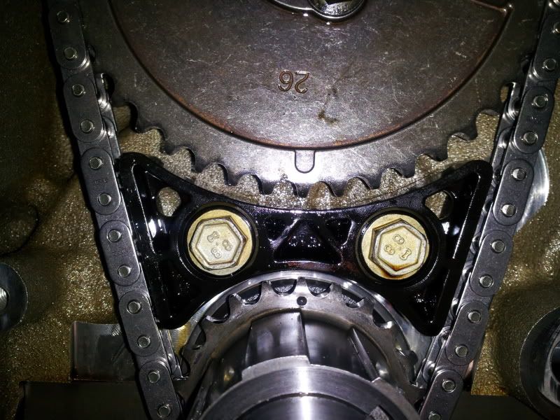
All lined up....
CLICK LINK FOR VIDEO OF CAM SETUP: http://s142.photobucket.com/albums/r...815_024902.mp4
1. Do I just torque them to spec or is it like a GEN 1 SBC where i have to set valve lash? What is the procedure for reinstalling the roller rockers.
2. I have been reading threads about poor valvetrain geometry causing excessive wear on valve guides... does this apply to me, and if so, do I need adjustable rocker arms?
Stay tuned for more..........
Last edited by Danspeed1; 08-15-2012 at 06:45 AM.
08-15-2012, 08:48 AM
#8
Race Director

Member Since: Mar 2011
Location: SW Florida
Posts: 13,256
Received 3,089 Likes
on
2,078 Posts
2021 C6 of the Year Finalist - Modified

I replaced the cam in my old Trans-Am which had the LS1 engine, but I believe the valvetrain is the same for the LS2 that you have.
The valve lash is non-adjustable ... just torque the bolts down to spec. The only way to make an adjustment to valve lash is by installing various length pushrods.
Since your aftermarket cam has more lift that the OEM cam, you will find that your new aftermarket cam will also have an decreased (smaller) "base circle" ... The base circle is the distance from the centerline of the cam out to the backside of the cam lobe. Increase the cam's lift, and the cam's base circle will decrease.
With that understanding, you would be wise to install 7.450" pushrods instead of the standard 7.400" OEM rods. That extra .050" (50 thousands) in length will make up for the decrease you now have in the aftermarket cam's base circle.
Remember, for optimum performance and valvetrain noise reduction, the hydraulic lifters need the correct "pre-load", and that means that you need the correct length pushrods, since there is no rocker arm adjustments on these LSx engines.
NOTE: The above applies only if you have not milled the heads .... Milling the heads does the opposite of installing a high lift cam. If you were to only mill the heads lets say .050" (and not change the cam), then you would need a .050" shorter pushrods in order to re-achieve the correct lifter preload.
Ron,
EDIT: And as always, when in doubt, check first with a realiable engine builder that will answer any of your questions.
.
Last edited by Turbo6TA; 08-15-2012 at 09:16 AM.
08-15-2012, 09:47 AM
#9
Race Director
Member Since: Mar 2011
Location: SW Florida
Posts: 13,256
Received 3,089 Likes
on
2,078 Posts
2021 C6 of the Year Finalist - Modified
It's like the 5th grader drawing I made below ... The correct lifter preload is made when the pushrod is the correct length in that it will push the plunger inside the hydraulic lifter about half way of it's total available travel when the cam is turned so that the lifter is resting on the heal (backside) of the can lobe.
I have been told that the total available travel of the lifter's internal plunger is about 0.160" (one hundred sixty thousands) .... so, half that distance would be about .080" (eighty thousands of an inch).
Hence, .080" lifter preload would be correct for the LXs engines.

Disclaimer: Don't quote me on those numbers. But .080" is what I have heard from more than 1 person.
.
I have been told that the total available travel of the lifter's internal plunger is about 0.160" (one hundred sixty thousands) .... so, half that distance would be about .080" (eighty thousands of an inch).
Hence, .080" lifter preload would be correct for the LXs engines.
Disclaimer: Don't quote me on those numbers. But .080" is what I have heard from more than 1 person.
.
Last edited by Turbo6TA; 08-15-2012 at 02:00 PM.
08-15-2012, 10:15 AM
#10
Race Director
Member Since: Mar 2011
Location: SW Florida
Posts: 13,256
Received 3,089 Likes
on
2,078 Posts
2021 C6 of the Year Finalist - Modified
Here is a good way to check if you have the correct length pushrods (correct lifter preload) in your LSx engine:
1. Turning the engine, bring one of the cylinders to TDC on the compression stroke. The valves on that cyl. will be fully closed.
2. Now, fully loosen one of the rocker arm bolts on that cyl.
3. Then start turning the rocker arm bolt down until the lifter is at "zero lash". You will be able to tell it is at zero lash when the rocker bolt gets very hard to turn. It gets hard to turn because the valve spring starts to compress. Again, stop turning the bolt as soon as you feel resistance to turning.
4. Mark the bolt with a marker.
5. Now count how many turns it takes to completely tighten the rocker bolt to 22 FT/LB.
The bolt should have turned 1 3/4 turns for the acceptable GM lifter peload.
If you don't get the 1 3/4 turns of preload, you need a different length pushrod. (IE: shorter rod if it takes much more than 1 3/4 turns, and a longer rod if it takes much less than 1 3/4 turns).
NOTE: You really only need to do this on one cylinder. The rest will be the same.
________________________________________ _________
And why do I know this? .... If you take a stock LSx engine that has not had the valvetrain modified, you will find that it will also take about 1 3/4 turns of the bolt to go from "0" lash to 22 Ft Lbs torque .... It should also be the same after you replaced the camshaft and installed the correct length pushrods for your application.
.
Last edited by Turbo6TA; 08-18-2012 at 04:43 PM.
08-15-2012, 12:28 PM
#11
Le Mans Master

Member Since: May 2011
Location: Tampa FL (formerly Justinjor)
Posts: 5,022
Likes: 0
Received 14 Likes
on
9 Posts
Tech Contributor
St. Jude Donor '11-'12-'13-'14
The main part I find alarming is the fact you didn't find a blue O ring either on your pickup tube or stuffed inside the oil pump itself.
Is it possible it fell out when you separated the two? Maybe its in the oil pan?
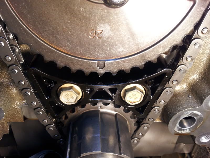
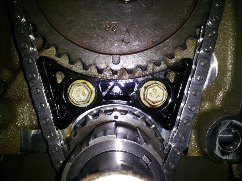
Regarding the tension on the timing chain, this is my C5R chain after about 15k miles. I broke the plastic tensioner and had to replace it with the dampener.
Is it possible it fell out when you separated the two? Maybe its in the oil pan?
Regarding the tension on the timing chain, this is my C5R chain after about 15k miles. I broke the plastic tensioner and had to replace it with the dampener.
 08-15-2012, 12:53 PM
#13
Le Mans Master
Op, when you go to tq your new pulley use/borrow/purchase the flywheel locking tool. It helps tremendously to get it torqued correctly and easily. The cost is less than $100 and you can always resell it easily.
08-15-2012, 02:28 PM
#14
Drifting
Thread Starter
The main part I find alarming is the fact you didn't find a blue O ring either on your pickup tube or stuffed inside the oil pump itself.
Is it possible it fell out when you separated the two? Maybe its in the oil pan?
Regarding the tension on the timing chain, this is my C5R chain after about 15k miles. I broke the plastic tensioner and had to replace it with the dampener.
Is it possible it fell out when you separated the two? Maybe its in the oil pan?
Regarding the tension on the timing chain, this is my C5R chain after about 15k miles. I broke the plastic tensioner and had to replace it with the dampener.
I am going to make the same video you did and post it so you guys can critique it
08-15-2012, 02:45 PM
#15
Le Mans Master
Member Since: May 2011
Location: Tampa FL (formerly Justinjor)
Posts: 5,022
Likes: 0
Received 14 Likes
on
9 Posts
Tech Contributor
St. Jude Donor '11-'12-'13-'14
Does it move more than mine? Timing chains aren't supposed to be super tight anyway so even if it does have a little more play than mine, I don't think I would sweat it.
08-15-2012, 02:59 PM
#16
Drifting
Thread Starter
FOUND THE O-RING! It landed under the vehicle when I removed the pump. I will try and get a hold of a new one today.
Is there honestly any benefit to upgrading the oil pump for my application?
DG
08-15-2012, 03:05 PM
#17
Le Mans Master
Member Since: May 2011
Location: Tampa FL (formerly Justinjor)
Posts: 5,022
Likes: 0
Received 14 Likes
on
9 Posts
Tech Contributor
St. Jude Donor '11-'12-'13-'14
Mine moved that much when I first put it in. The video was more or less to show/confirm the lack of stretch after 15k miles, 180 dragstrip passes and lots of highway pulls.
Good deal with the O ring. Was it damaged? You can likely just wipe it off with a clean rag unless it got pinched or something.
Good deal with the O ring. Was it damaged? You can likely just wipe it off with a clean rag unless it got pinched or something.
08-15-2012, 03:10 PM
#18
Drifting
Thread Starter
Mine moved that much when I first put it in. The video was more or less to show/confirm the lack of stretch after 15k miles, 180 dragstrip passes and lots of highway pulls.
Good deal with the O ring. Was it damaged? You can likely just wipe it off with a clean rag unless it got pinched or something.
Good deal with the O ring. Was it damaged? You can likely just wipe it off with a clean rag unless it got pinched or something.
O ring looks OK. If I can get a new one I will install it, if GM is 10 days out like they usually are, the old one goes back in.
DG
08-15-2012, 03:15 PM
#20
Drifting
Thread Starter
Alright, I will try and get some more done tonight or tomorrow... I now have to drive to UPS because the rest of my parts are sitting over there.... missed the truck this morning when I overslept from 8am-noon
DG
DG