
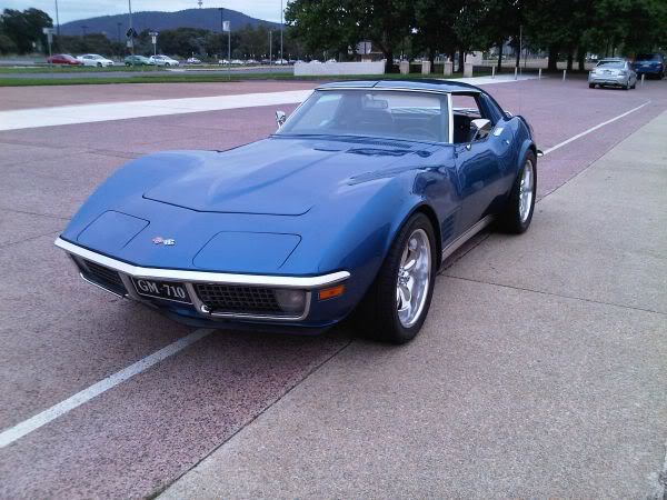
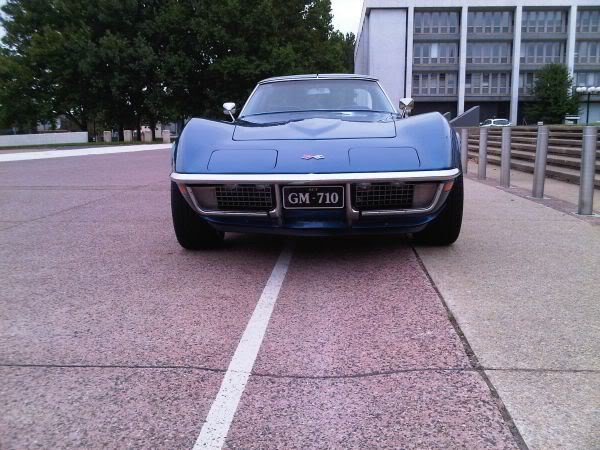
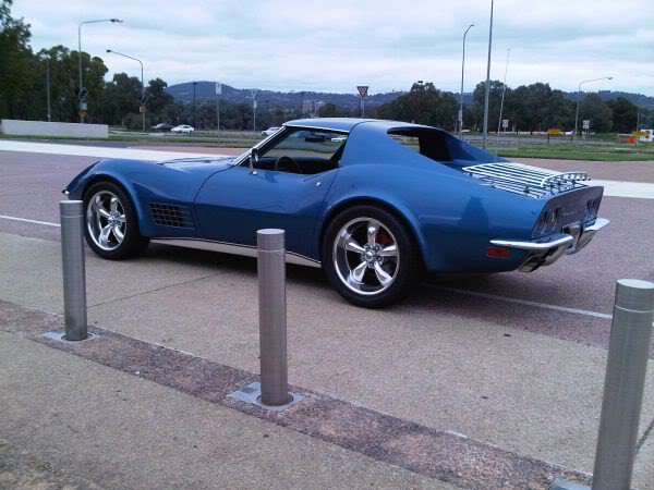
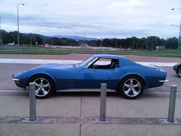
1971 Journey
 02-18-2013, 07:39 PM
#161
Melting Slicks

Thread Starter


January 2011
My electric fans turned up this morning
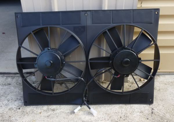
All work fine for a SPAL clone.
Was off ebay from Skip White Performance and great value.
http://stores.ebay.com/whiteperformance1.
Added to my collection of engine bay parts for when I start on that.
My electric fans turned up this morning
All work fine for a SPAL clone.
Was off ebay from Skip White Performance and great value.
http://stores.ebay.com/whiteperformance1.
Added to my collection of engine bay parts for when I start on that.
Last edited by CraigH; 04-09-2023 at 08:34 PM.
 02-18-2013, 07:39 PM
#162
Melting Slicks
Thread Starter
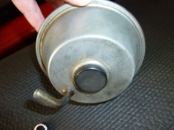
Have been looking for a replacement vapor canister for a while and had hoped to get one at Kissimmee swap meet but did not find one.
Was visiting Chip Foose's workshop today and poked my head into Automotive Expertise Unlimited (Steve Luvisi) across the road.
The shop works on vettes and has been on a few Overhaulin episodes.
He suggested I try a Corvette part trader in Gardena.
Wow what an experience.......
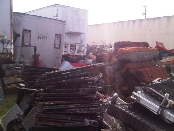
Building after building of parts and heaps of open air stuff.....10 or so tractor trailers filled to the brim.
He does not wreck but trades in parts.
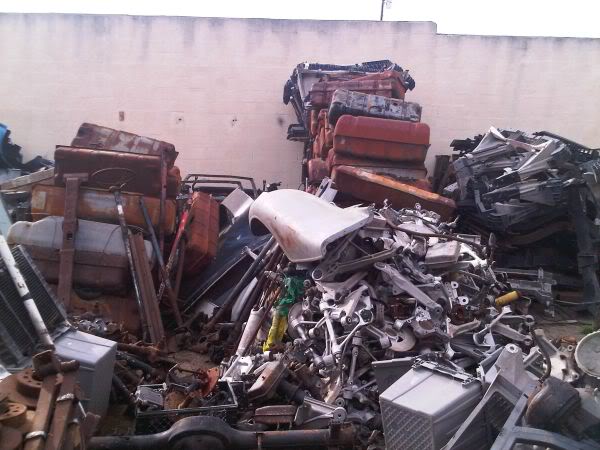
In the end he led us into a trailer and showed us 5 huge boxes of canisters and said go for it.
The luck was that the one he got out to show me where to look was exactly the part # for my 71.
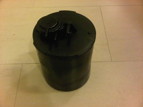
I have pulled it apart and its working fine.
Just a couple of shots of the outside parts...........
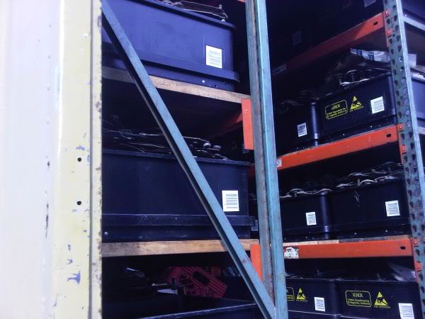
The inside of a container.
Was visiting Chip Foose's workshop today and poked my head into Automotive Expertise Unlimited (Steve Luvisi) across the road.
The shop works on vettes and has been on a few Overhaulin episodes.
He suggested I try a Corvette part trader in Gardena.
Wow what an experience.......
Building after building of parts and heaps of open air stuff.....10 or so tractor trailers filled to the brim.
He does not wreck but trades in parts.
In the end he led us into a trailer and showed us 5 huge boxes of canisters and said go for it.
The luck was that the one he got out to show me where to look was exactly the part # for my 71.
I have pulled it apart and its working fine.
Just a couple of shots of the outside parts...........
The inside of a container.
Last edited by CraigH; 04-09-2023 at 08:35 PM.
02-18-2013, 07:40 PM
#163
Melting Slicks
Thread Starter
Started some research today for a friend of mine who is going to build my thermo fan controller.
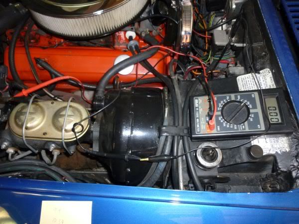
In Vette Maggazine Jan 2011 there is a good article explaining how the fuel sender and gauge work. The temp gauge is very similar in principle with a varying resistance in the sender that changes how much current can flow that way vs into the needle deflection.
So I have been measuring voltage on the sender line from when the car is cold through to when it is at temp (180).
The car was not 100% cold as I had driven it earlier today but I got.
10.34 volts at start
Then it worked its way down to 9.22 volts when it was sitting at 180 degrees measures with a temp gun on the thermo housing.
Problem was it would not go much over that while idling away.
After a bit of throttle work it went to 9.09 volts and 182 degrees.
I may have to pull the fan to finish the testing.
What we have in mind is
- a sensor that reads the sender unit voltage.
- allows you to set a start and stop temp for each fan
- allows you to override the control and force them on.
- displays an on status light in the end of the two push button controls.
- Possibly a pulse width modulation circuit to run the fans at less than 100% speed.
Last edited by CraigH; 04-09-2023 at 08:33 PM.
02-18-2013, 07:41 PM
#165
Melting Slicks
Thread Starter
I did another set of temperature and voltage readings from cold to 200 degrees.
My friend then came back with a computed polynomial trend line and the formula which he can use to adjust the readings in the fan controller.
!!!!!!!
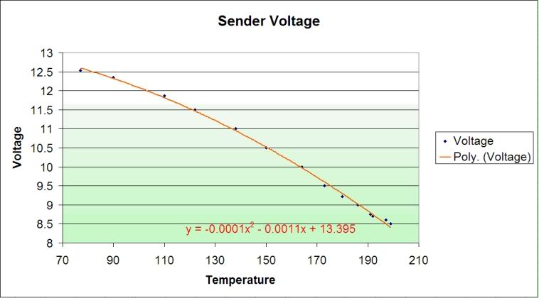
My friend then came back with a computed polynomial trend line and the formula which he can use to adjust the readings in the fan controller.
!!!!!!!
Last edited by CraigH; 04-09-2023 at 08:33 PM.
02-18-2013, 07:43 PM
#166
Melting Slicks
Thread Starter
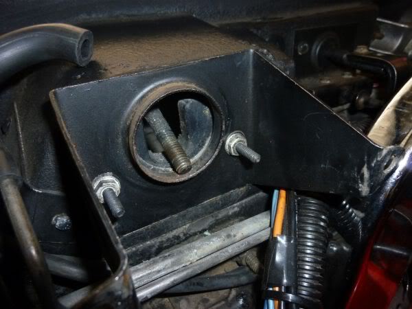
Have had a vacuum leak in the wiper door actuator so decided to replace it.
I could have replaced the seals but I wanted one with the nice original finish. In fact I probably could have sprayed it the color if I could find the correct one.
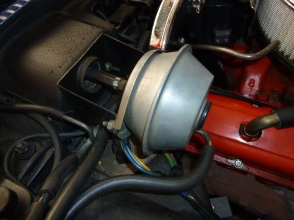
First loosen the locking nut then the 2 bolts that hold the actuator on then remove the barrel nut.
Front seal was ok but back one is shot.
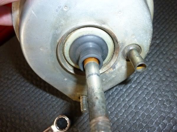
Will fit the new one tomorrow.
I could have replaced the seals but I wanted one with the nice original finish. In fact I probably could have sprayed it the color if I could find the correct one.
First loosen the locking nut then the 2 bolts that hold the actuator on then remove the barrel nut.
Front seal was ok but back one is shot.
Will fit the new one tomorrow.
Last edited by CraigH; 04-09-2023 at 08:33 PM.
02-18-2013, 07:44 PM
#167
Melting Slicks
Thread Starter
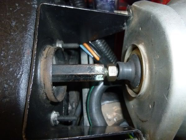
Cleaned up all the wiper door threaded shaft and painted the barrel nut.
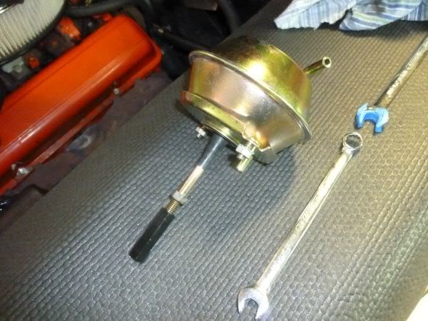
Extended the shaft of the actuator and put the rubber boot on then turned the barrel bolt till it touched the locking nut.
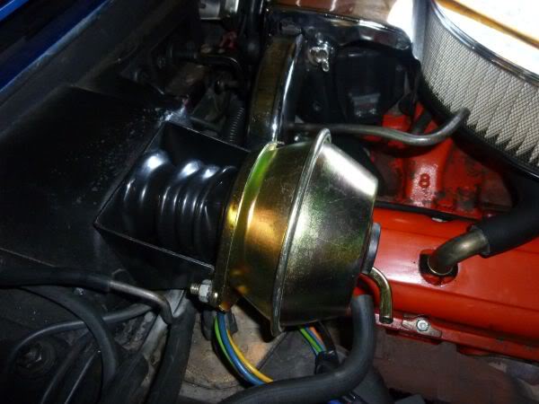
Tightened the mount nuts and attached the vacuum lines.
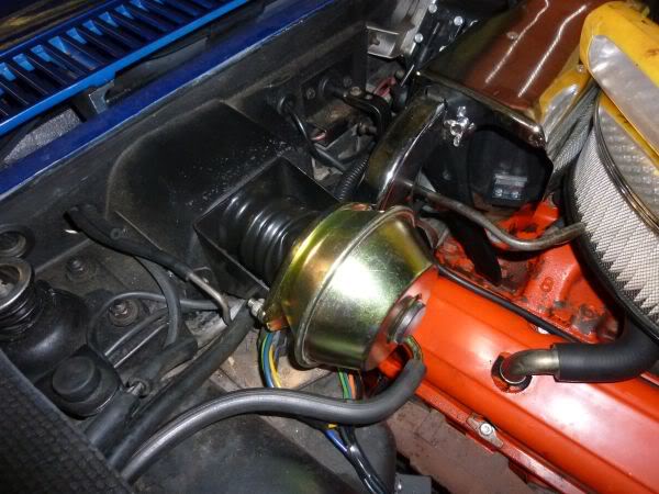
Tested wiper door for open and close and all good.
There is still some minor leaks in the control circuit in engine bay but that can wait till i replace all vacuum lines.
Extended the shaft of the actuator and put the rubber boot on then turned the barrel bolt till it touched the locking nut.
Tightened the mount nuts and attached the vacuum lines.
Tested wiper door for open and close and all good.
There is still some minor leaks in the control circuit in engine bay but that can wait till i replace all vacuum lines.
Last edited by CraigH; 04-09-2023 at 08:32 PM.
02-18-2013, 07:44 PM
#168
Melting Slicks
Thread Starter
Not looking to take on anything big at present but wanted to do a few tidy up things.
I read that the Upper A Arm should never be tightened without some shims and my drivers side had none
Passenger had more shim in back than front.
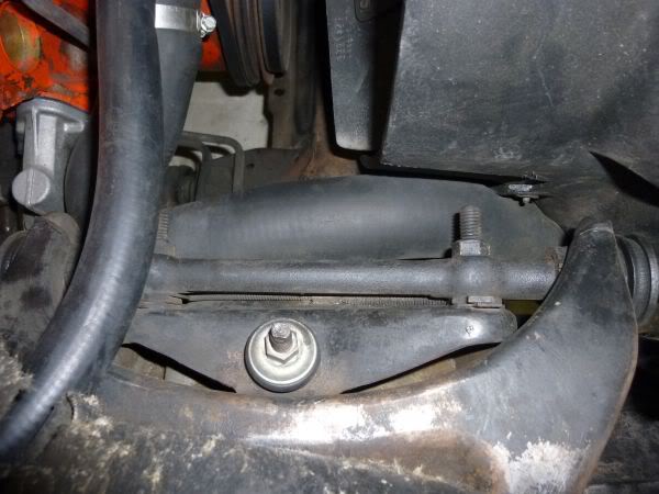
So I put two shims rear and one front on the drivers side. Wound back the nuts inserted and tightened.
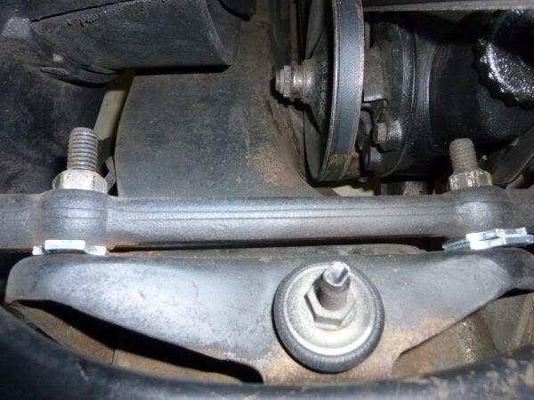
Not worried re alignment as we had not done a full one on it yet because we were waiting for the new springs.
This at least will add a bit of Camber :-)
I read that the Upper A Arm should never be tightened without some shims and my drivers side had none
Passenger had more shim in back than front.
So I put two shims rear and one front on the drivers side. Wound back the nuts inserted and tightened.
Not worried re alignment as we had not done a full one on it yet because we were waiting for the new springs.
This at least will add a bit of Camber :-)
Last edited by CraigH; 04-09-2023 at 08:32 PM.
02-18-2013, 07:45 PM
#169
Melting Slicks
Thread Starter
Have replaced the visor support rods as the originals made the visors very tight to use.
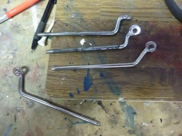
The new sun visors needed to be tightened slightly for the new pins.
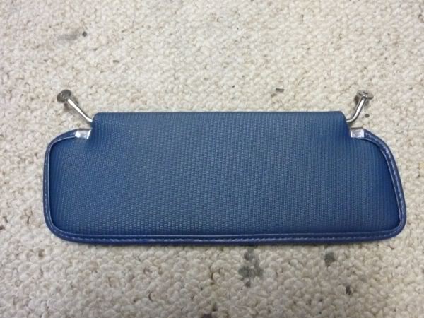
Finished visor in place.
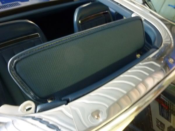
The Visor pins seem to be slightly different lengths (From Screw mount to visor) and I am not sure if its just bad build tolerances or it is meant to be that way.
Have tried them in all possible ways to get best fit.
The new sun visors needed to be tightened slightly for the new pins.
Finished visor in place.
The Visor pins seem to be slightly different lengths (From Screw mount to visor) and I am not sure if its just bad build tolerances or it is meant to be that way.
Have tried them in all possible ways to get best fit.
Last edited by CraigH; 04-09-2023 at 08:32 PM.
02-18-2013, 07:45 PM
#170
Melting Slicks
Thread Starter
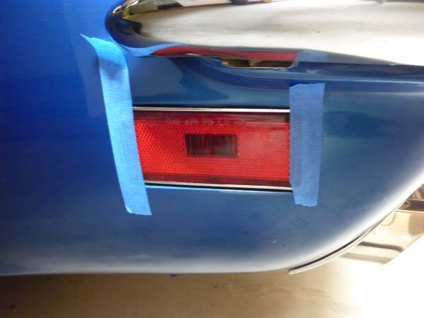
One of my rear marker lenses was a little bit loose so I pulled out the lens and cleaned out the frame.
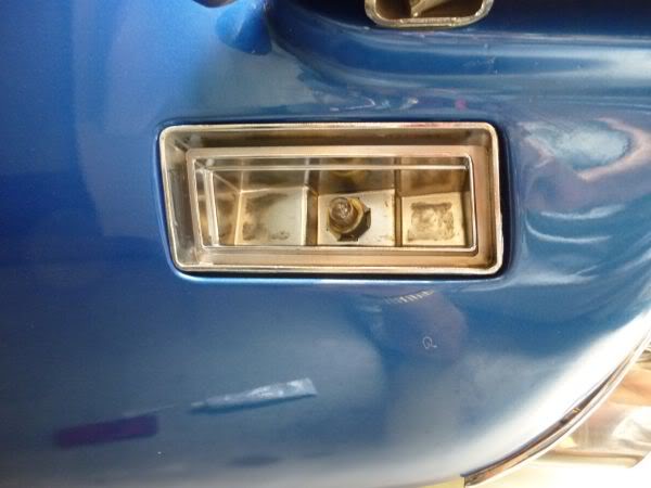
Also cleaned up the lens and reflector.
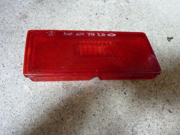
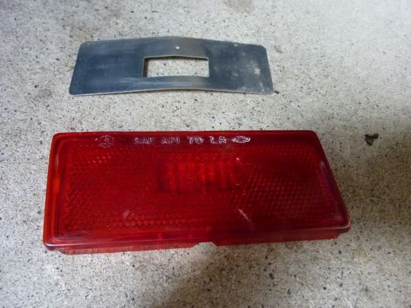
New bead of silicone and the lens goes back in.
Also cleaned up the lens and reflector.
New bead of silicone and the lens goes back in.
Last edited by CraigH; 04-09-2023 at 08:32 PM.
02-18-2013, 07:45 PM
#171
Melting Slicks
Thread Starter
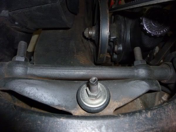
Did a backyard wheel alignment on the Vette.
I thought that I was bordering on Toe out and also not enough Camber on the drivers side.
The camber was fixed with the shims that I fitted earlier but the Toe needed attention.
At its crudest level I straightened the wheels and placed a long straight edge on the outside of each wheel then measured the distance between in front and behind the wheels.
After a series of adjustments of the tie rods I got to a point where i was relatively happy with a small amount or Toe in.
Vette now seems to steer better with less tram lining and darting.
This is obviously not a substitute for a proper alignment but ok as a stop gap.
02-18-2013, 07:46 PM
#172
Melting Slicks
Thread Starter
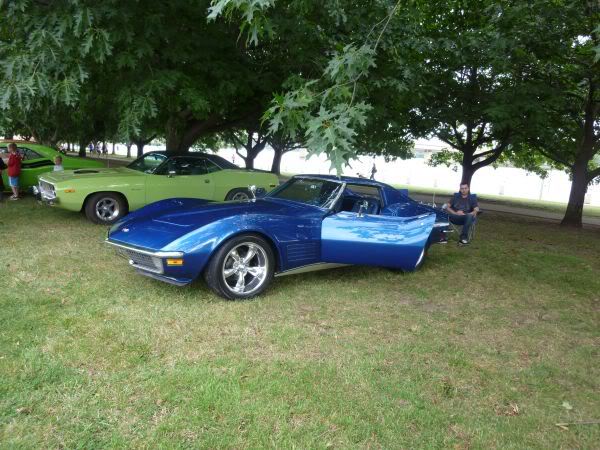
I attended the Canberra Mustang Show today.
Lots of nice Stangs and a fair number of non Stangs.
I was the only Vette though. :-(
Lots of nice Stangs and a fair number of non Stangs.
I was the only Vette though. :-(
Last edited by CraigH; 04-09-2023 at 08:39 PM.
02-18-2013, 07:46 PM
#173
Melting Slicks
Thread Starter
February 2011
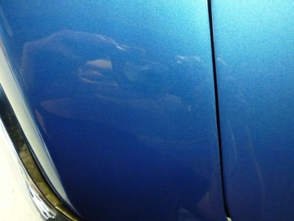
Its always a risk at a show that your car will get a scratch or chip etc.
Well I had thought that the attendees were all great, no one event tried to pick up my original 1971 Corvette brochure, very respectful bunch...... but when I got home I noticed a chip about 5x5 mm next to the front light.
It was not a stone chip as I could see heaps of finger prints next to it and where someone had wiped it to see if it would come off. Looks like someone dropped something on it while leaning over or hit it with and umbrella or who knows what. :evil:
So I cleaned it out and put 4 layers of touch up paint in it to get it a bit higher than the rest of the paint. Using 2000 wet an dry between some of the coats and to finish.
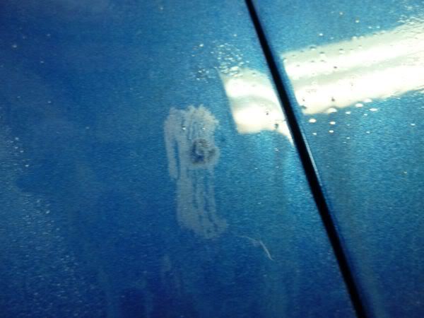
So the finished repair is visible as a slightly different color under flouros but outside its not realty noticeable.
I was looking at all the guys with XR6 Turbos and FPV's with chain rails around the cars thinking what overkill......possibly notl.....
Its always a risk at a show that your car will get a scratch or chip etc.
Well I had thought that the attendees were all great, no one event tried to pick up my original 1971 Corvette brochure, very respectful bunch...... but when I got home I noticed a chip about 5x5 mm next to the front light.
It was not a stone chip as I could see heaps of finger prints next to it and where someone had wiped it to see if it would come off. Looks like someone dropped something on it while leaning over or hit it with and umbrella or who knows what. :evil:
So I cleaned it out and put 4 layers of touch up paint in it to get it a bit higher than the rest of the paint. Using 2000 wet an dry between some of the coats and to finish.
So the finished repair is visible as a slightly different color under flouros but outside its not realty noticeable.
I was looking at all the guys with XR6 Turbos and FPV's with chain rails around the cars thinking what overkill......possibly notl.....
Last edited by CraigH; 04-09-2023 at 08:25 PM.
02-18-2013, 07:47 PM
#174
Melting Slicks
Thread Starter
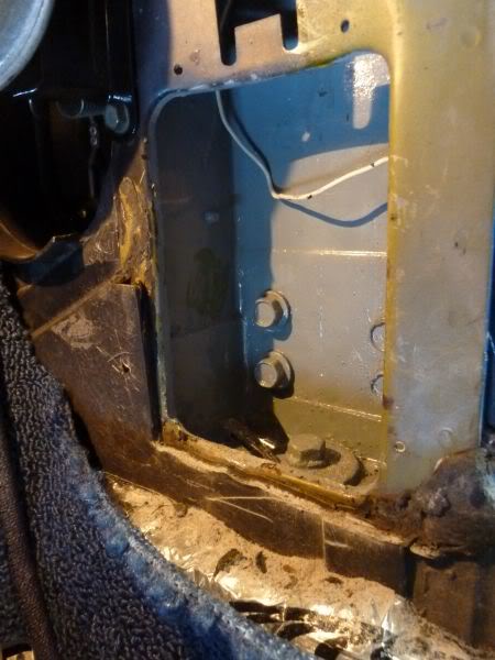
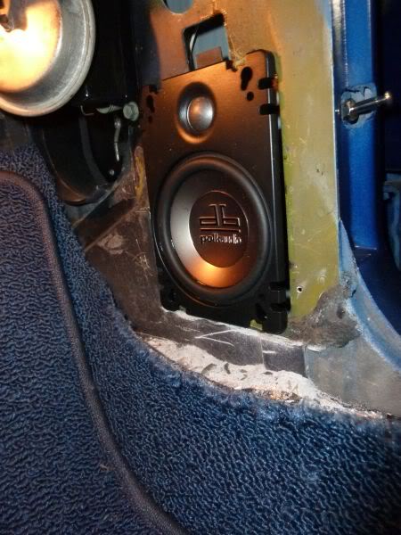
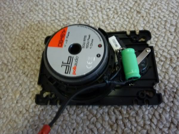
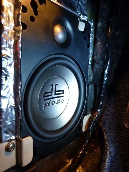
Had a bit of time tonight so did a rough fit for the kick panel speakers.
They are 4x6 Polk plate speakers so will need some form of bass block added so they dont over drive.
Will all be hidden behind kick panel.
Had purchased some 4x10s as that was the factory size in 68 & 69 but a modern speaker magnet of any reasonable size would not fit.
First I trimmed the fiberglass below so it would sit down on an edge and flush.
Trial fit.
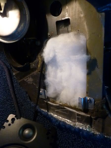
Fill with Dacron.
Build some simple aluminum tab brackets.
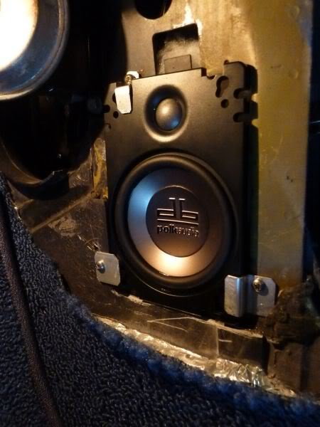
Some adjustments to the tabs and some 3M bitumen sealer around the fiberglass edge and a little Dynamat and it will all be sealed up nicely.
Will do some tests with capacitors fist to get blocker correct.
They are 4x6 Polk plate speakers so will need some form of bass block added so they dont over drive.
Will all be hidden behind kick panel.
Had purchased some 4x10s as that was the factory size in 68 & 69 but a modern speaker magnet of any reasonable size would not fit.
First I trimmed the fiberglass below so it would sit down on an edge and flush.
Trial fit.
Fill with Dacron.
Build some simple aluminum tab brackets.
Some adjustments to the tabs and some 3M bitumen sealer around the fiberglass edge and a little Dynamat and it will all be sealed up nicely.
Will do some tests with capacitors fist to get blocker correct.
Last edited by CraigH; 04-09-2023 at 08:24 PM.
02-18-2013, 07:47 PM
#175
Melting Slicks
Thread Starter
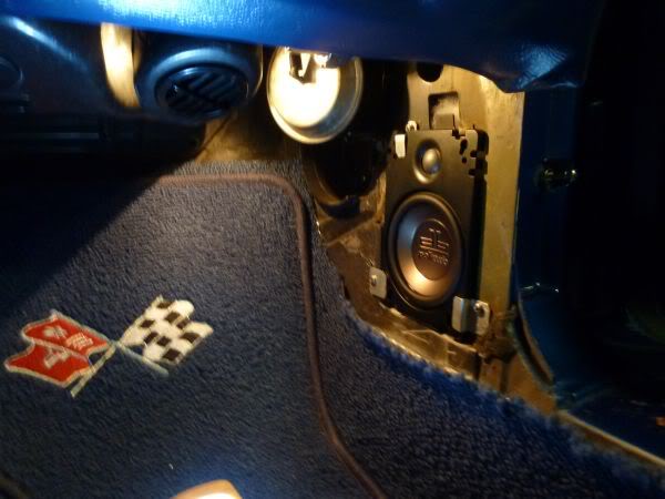
Speaker wiring done with capacitor to block low bass.
Both sides trial fitted.
Need to remove, paint and seal up any areas that were trimmed, neaten the brackets then refit.
Both sides trial fitted.
Need to remove, paint and seal up any areas that were trimmed, neaten the brackets then refit.
Last edited by CraigH; 04-09-2023 at 08:24 PM.
02-18-2013, 07:48 PM
#176
Melting Slicks
Thread Starter
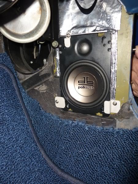
Finished off the speakers today.
painted the glass edges that were trimmed, neatened up the brackets then media blasted them smooth.
Fitted speaker with some Dynamat over pillar holes etc.
painted the glass edges that were trimmed, neatened up the brackets then media blasted them smooth.
Fitted speaker with some Dynamat over pillar holes etc.
Last edited by CraigH; 04-09-2023 at 08:23 PM.
 02-18-2013, 07:49 PM
#178
Melting Slicks
Thread Starter
March 2011
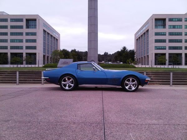
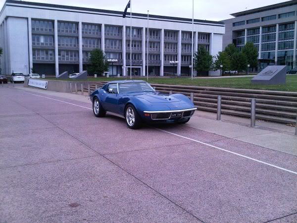
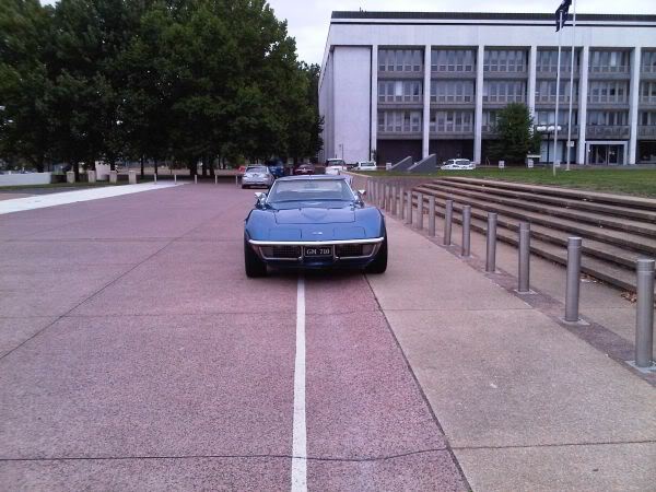
Met up with some of the Canberra Corvette club members who were doing a run past Cooma today.
Took a few photos in front of the Defense Department before they arrived.
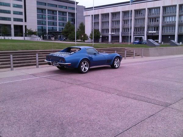
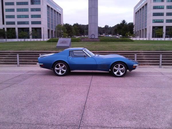
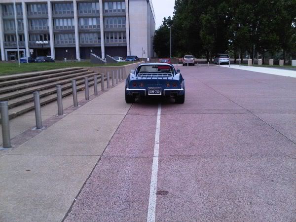
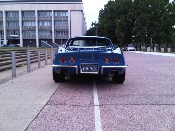

Met up with some of the Canberra Corvette club members who were doing a run past Cooma today.
Took a few photos in front of the Defense Department before they arrived.
Last edited by CraigH; 04-09-2023 at 08:23 PM.
The following users liked this post:
new 2 me (10-31-2019)
02-18-2013, 07:50 PM
#179
Melting Slicks
Thread Starter
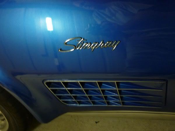
Ok Jethro.....You shamed me into it.
New badge is 4 pin old one is 3 so I pulled both badges and found passenger side had 4 holes.
Easy, new one goes on passenger side old one on drivers.
New one has fitting tape on back as well as pins so after a little bending fitted perfectly.
It also worked with speed nuts for extra protection.
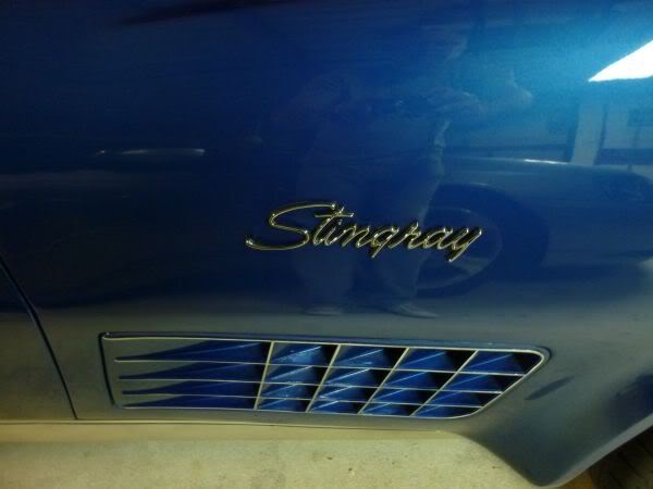
Original was fitted and secured behind with cut down speaker flat nuts as the pins are very short.
New badge is 4 pin old one is 3 so I pulled both badges and found passenger side had 4 holes.
Easy, new one goes on passenger side old one on drivers.
New one has fitting tape on back as well as pins so after a little bending fitted perfectly.
It also worked with speed nuts for extra protection.
Original was fitted and secured behind with cut down speaker flat nuts as the pins are very short.
Last edited by CraigH; 04-09-2023 at 08:23 PM.
02-18-2013, 07:51 PM
#180
Melting Slicks
Thread Starter
March 2011
Some Toys turned up while I was away this week.

Speed Direct Spreader bar.
Bilstein Sports Shocks for rear.
Speed Direct/QA1 Coil Over Kit for front with dual adjustable shocks and bearing base plates.
I will test fit the coil overs in the front first to see everything is ok then later I will tear out all the front suspension and rebuild, possibly with new upper a-arms that provide better adjustment. :-)
Some Toys turned up while I was away this week.
Speed Direct Spreader bar.
Bilstein Sports Shocks for rear.
Speed Direct/QA1 Coil Over Kit for front with dual adjustable shocks and bearing base plates.
I will test fit the coil overs in the front first to see everything is ok then later I will tear out all the front suspension and rebuild, possibly with new upper a-arms that provide better adjustment. :-)
Last edited by CraigH; 11-08-2017 at 03:40 AM.