

 02-20-2015, 01:03 PM
Last edit by: IB Advertising
See related guides and technical advice from our community experts:
Browse all: Exterior How-Tos
- C6 Corvette Favorite C6 Picture Gallery
Important information to help you understand your Corvette..
Browse all: Exterior How-Tos

C6 FAQ (Frequently Asked Questions)


 12-23-2005, 05:42 AM
#103
Get Some!


NAV MP3 Static FIX !!!!!!! Finally !
--------------------------------------------------------------------------------
ASI Resolution - Poor and/or No Radio Reception, Intermittent Static on FM with Navigational Radio System (Update Radio Software) #05-08-44-014A - (Dec 9, 2005)
Poor and/or No Radio Reception, Intermittent Static on FM with Navigational Radio System (Update Radio Software)
2005 Chevrolet Corvette (Domestic and Export) with Navigation Radio
This bulletin is being revised to provide correction information. Please discard Corporate Bulletin Number 05-08-44-014 (Section 08 -- Body and Accessories).
Condition
Some customers may comment on the following conditions:
� Static is heard on stations with an otherwise strong signal, after the ignition is turned on.
� The radio is unable to stop at specific stations when using the "seek" function.
Correction
DO NOT REPLACE THE RADIO
Important: The software is updated using a CD, not through SPS programming. New software, P/N 15853651, can be obtained from GMSPO. Dealers should retain the service CD for future use.
The software update will do the following:
� Modify the signal interface with the ARS module to correct the reception condition.
� Add an on-screen message to remind the customer that a destination is required before a route can be planned.
� Add MP3 functionality.
The navigation/radio software, P/N 15853651, should be updated using the following procedure:
Important:
� This software can ONLY be used for updating the 2005 Corvette navigation radio, P/N 15263014. Do not use these CDs to update any other vehicle's navigation radio. The radio part number can be verified via the Tech 2�.
� Software CDs and a Tech 2� are required to complete this procedure.
� Use of latex gloves is recommended to avoid fingerprints on the products and/or discs.
� If the vehicle is turned "off" during updating, the "software updating" process may not work and a new navigation radio will be required.
Follow the steps below to complete the software update.
Turn the ignition "on" with the engine "off" by holding the ignition switch in "ACC" mode for at least 10 seconds.
Open the tilt screen (navigation screen) to gain access to the DVD drive.
Eject the navigation DVD from the DVD drive (bottom slot).
Important: It may be necessary to close the radio screen for Disc 1 - Navigation to begin operation. If the navigation software version in the navigation radio is the same or higher than v.1312, the software updating will not start.
Insert Disc 1- Navigation software version 1312 into the DVD slot.
"Preparing to Load System Software" is displayed on the screen along with a progress bar. It will take approximately 5 minutes for Disc 1 to load.
After Disc 1 - Navigation has completed the navigation system will automatically restart. Eject disc 1 from the DVD slot. Insert Disc 2 - Audio software version 01.0F into the DVD slot.
Important: Approximately 10-15 seconds after inserting the disc, the screen will go blank. It will appear that the radio has shut down and/or locked up. This is the mode the radio will go into when the software is updating. If the audio software version in the navigation radio is the same as v01.0F, the software updating will not start.
When Disc 2 is completed, the system will automatically restart. It will take approximately 5-10 minutes for the system to restart. Remove Disc 2 - Audio from the DVD drive.
Turn the vehicle off. Open and close the driver's door and wait for 60 seconds.
Turn the vehicle on and reinstall the customer's navigation DVD.
Press the "NAV" button on the navigation radio, then press the "Agree" soft key on the screen.
After the map screen is displayed, touch the map screen the confirm that the map can be scrolled.
Using the Tech 2�, clear any/all DTCs from the radio.
Part Information
Part Number
Description
15853651
Disc -- Navigation Data
Warranty Information
For vehicles repaired under warranty, use:
Labor Operation
Description
Labor Time
R9707*
CD Update - Radio/Navigation Software
0.5 hr
*This is a unique labor operation number for bulletin use only. It will not be published in the Labor Time Guide


 01-22-2006, 11:48 AM
#108
Get Some!
C6 Dead Batteries - A GM Response
--------------------------------------------------------------------------------
[I published this in the General Section near the end of a very long thread on the DBS issue. Thought it would be of benefit to post it here as well]
Sometime ago Jeff and I asked for information regarding your DBS problem, that we would forward it to the GM team working on the solution. As a result, several C6 owners were put in direct contact with our source and have been working with GM to identify the root cause. A number of you have suggested that GM is wearing blinders, which is not the case.
I received the following letter from our "Friend in High Places" which provides an update as to GM's efforts in trying to determine the cause and provide a fix. It is addressed to those of us who have been in direct contact. You are NOT being left out in the cold by GM!
Our source asks a question of us at the bottom of his letter. Please reply to me with any input and I'll see that he gets all responses: c5bruce@adelphia.net
Hello Everyone: I'm sure most of you do not know each other but you are all Corvette enthusiast that I have been communicating with regarding your dead battery syndrome. I just wanted to give everyone an update so you know where we stand. I was off on vacation in November and December but rest assured the project is moving forward.
There is a complete team working the issue and a specialist in root cause analysis has also been assigned. We have been successful in identifying
some issues that are not causing the condition and we also believe that it can not all be associated with customers not putting the car in reverse. Especially with this group I trust you all fully understand and practice the proper shut down procedures.
As you know for 2006 the shift to reverse feature was eliminated. GM was successful in convincing the Federal Government that this feature was not
essential in preventing car theft. While the Fed ruled GM could discontinue it on future models it did not approve a retrofit that would eliminate the requirement for 2005 models. So 2005 cars are stuck with it.
Also for 2006 the column lock feature has been removed. We are not sure how much, if any, this influences DBS but it is a difference we are investigating.
We understand there are two switches that are used to tell the BCM the shifter is placed in reverse. If these switches are not activated the BCM does not actually shut down the electrical system. The car could believe it is not in reverse and stays live, even when the shifter is in reverse.
We are developing a couple of testers that can easily be installed in a customer car and monitor these circuit and switches. We will be installing it in one customer car next week. We have had two test
computers built that are currently on customer cars that actually monitor battery voltage, amp draw and ignition cycles every 30 seconds. The computer is not invasive and the customer can drive the car while it stays connected and monitors the data. We are looking to our engineering group for more improvements that can determine if a module is not going to sleep as it is intended and identify the naughty module.
We are also looking at stray radio waves that could be waking up the BCM once it is asleep much like doing an key fob button press. In one case we identified a customer's car that lived close to the security gate for their neighborhood. Every time someone hit the button to open their security gate their car would wake up and go through the 20 minute shut down
procedure.
Each of you have been supplying information and data particular to your car and some of your friends. I thank you for your continued support and patience. We are making progress but since I have no idea how long the road is, I can only tell you when we can finish the race. Rest assured we will not quit until we identify the issue and correct it. As more information becomes available I will pass it to you.
If you are still driving your cars and don't happen to be hampered by Michigan's winter and bad roads, you could try something for me. As you drive and park the car and shift to reverse, once the car is in reverse do you ever get the message to shift to reverse even though it is there? Just curious. If you do experience this event please let me know.
Have a great January, enjoy the Detroit Auto Show if you are coming this way.
Originally Posted by bob 57 chevy
I have an 05 with MN6 and had several DBS (Dead Battery Syndrome) episodes. The car has been to the dealer twice with no resolution. On one trip the dealer replaced the battery but the new one went dead in just a few days. Then I tried the following procedure originally posted by Hoosose. Since then I have not had a single dead battery.
Perform a normal shut down with the shifter in reverse. Then move the shifter to neutral. If the car is actually shut down you should not see a message on the DIC. If the DIC says “shift to reverse” then move the shifter back to reverse and try again. After the car is properly shut down and the shifter has been moved to neutral you can shift to any gear.
BTW, I have never seen "shift to reverse" after moving the shifter to neutral, but others have. Nonetheless the problem has stopped. So even if you don't get a message on the DIC when shifting to neutral this action seems to force the shutdown to complete.
Please send me a private message if this does or doesn’t solve your problem. If it does solve the problem for you, like it has for me, I will find a way to get that information back to the proper people at GM.
Thanks for helping,
Bob
Last edited by LTC Z06; 05-31-2006 at 11:16 AM.
01-28-2006, 09:55 AM
#109
Get Some!
From David Farmer:
http://forums.corvetteforum.com/show...0&page=1&pp=20
DIY Cold Airbox Save $$$$
--------------------------------------------------------------------------------
I got so sick of reading about $600 airboxes, that I decided to build one from the OEM stuff. It is almost like GM designed the parts for it. Just pull the airbox off, swap the left/right filter holders (mounting them upside down of the other side), cut 2 holes in the shroud, and voila.
The air filters hang down in the top of the shroud, catching tons of cool air. My accelerometer is dead, so I coulnd't get any before/after testing, but my MAF and air inlets are DEAD COLD after a hot run, and were always quite warm before.
I actually considered buying one of the high $$ intakes, but since none of the vendors here have ever helped my racing efforts, I'd rather help myself.
I was a little rushed today, but once I get an airtight seal, I put it within 90% of any of the aftermarket kits!
Like I Said in my follow up, I already had gauze filters in the car.
Here are some shots. I'll clean up my cuts, and build an aluminum shroud to seal off the outer edges. And/or, I'm thinking or trimming the area where the outer parts bolt to the primary, therefore narrowing the entire assembly slightly.
Already, it's working well, and I think with a little work, it will be great. I'm running the long course at VIR next month, and if there are any problems, that is where they would happen (nothing will).


Thanks!
http://www.DavidFarmerRacing.com/
http://forums.corvetteforum.com/show...0&page=1&pp=20
DIY Cold Airbox Save $$$$
--------------------------------------------------------------------------------
I got so sick of reading about $600 airboxes, that I decided to build one from the OEM stuff. It is almost like GM designed the parts for it. Just pull the airbox off, swap the left/right filter holders (mounting them upside down of the other side), cut 2 holes in the shroud, and voila.
The air filters hang down in the top of the shroud, catching tons of cool air. My accelerometer is dead, so I coulnd't get any before/after testing, but my MAF and air inlets are DEAD COLD after a hot run, and were always quite warm before.
I actually considered buying one of the high $$ intakes, but since none of the vendors here have ever helped my racing efforts, I'd rather help myself.
I was a little rushed today, but once I get an airtight seal, I put it within 90% of any of the aftermarket kits!
Like I Said in my follow up, I already had gauze filters in the car.
Here are some shots. I'll clean up my cuts, and build an aluminum shroud to seal off the outer edges. And/or, I'm thinking or trimming the area where the outer parts bolt to the primary, therefore narrowing the entire assembly slightly.
Already, it's working well, and I think with a little work, it will be great. I'm running the long course at VIR next month, and if there are any problems, that is where they would happen (nothing will).
Thanks!
http://www.DavidFarmerRacing.com/
02-06-2006, 09:51 AM
#110
Get Some!
Applies to C6 also.
Originally Posted by theadmiral94
In Other Words -- how to lift and support your C5 per the GM Manual
This article will translate and document the GM Manual�s procedures for lifting and supporting a C5 (based on a 2000) and clearly define the distinction between a �hydraulic jack� and where it can be placed -- versus -- �jack stands� and where they can be placed.
This is not to say other suggested procedures would not work without damage.
However, after struggling through so many different suggested procedures and the manual, I decided to put this together to help the next 'new to them' owner of a C5.
The goal of this write-up is to accurately convey the GM Manual�s information so anyone can determine if a suggested procedure deviates from GM recommendations.
This information is taken from GM�s 2000 Service Manual, Volume 1 of 3, General Information, pages 0-33.
I should also credit two other websites for their information, upon which some of this article is based :
:
The Idaho Corvette Page and Z06vette.com
First, to identify some large differences between many suggested procedures and what the GM�s manual recommends. The GM Manual states or implies:
1. �Jack Stands� should NOT be placed under the �frame rails� (regardless of whether �hockey pucks� are used or not).
2. A �hydraulic jack� should NOT be placed directly under the CENTER of the �OPTIONAL� front cross-member. The �Optional� Front cross-member is FORWARD of the front fiberglass transverse spring and is the �optional� front location for a �hydraulic jack�. By contrast, the �PREFERRED� front location is to the REAR of the fiberglass transverse spring, immediately forward of the oil pan. This 'PREFERRED' cross-member can have a 'hydraulic Jack' placed directly under the center, however, doing so will most likely contact and may damage the oil pan/oil drain plug, so it is NOT advisable either.
3. A �hydraulic jack� should NOT be placed directly under the CENTER of the rear cross-member to raise the rear of the car.
4. �Hockey Pucks� should NOT be used at the FRONT Frame Rail location when lifting the car with a �service lift�. The presumably larger flat rectangular �service lift� �pad� is to be placed with its long side parallel with and at or immediately forward of the front �hockey puck� AREA (note: this also assures a slightly higher rear end for proper oil draining from the oil pan).
Now on to what can be done.
First of all, here is the Service Manual�s vehicle diagram of the �Vehicle Lifting and Jacking Locations� (note: Jacking is NOT �Jack Stands�):
personal home page Lifting & Jacking Locations
The Service Manual has 3 sections within the �Lifting and Jacking the Vehicle section�. These sections can be easily switched and thereby confusing.
The FIRST SECTION is �Vehicle Lifting � Frame Contact Hoist� (i.e. a �service lift�). This section clarifies the use of the �hockey pucks� (special part # J43625) ONLY for the REAR, to be installed in the �rear frame rail shipping slots�. The presumably larger flat rectangular �service lift� �pad� is to be placed with its long side parallel with and at or immediately forward of the front �hockey puck� AREA (without a �hockey puck�) AND not touching the body panels.
The SECOND SECTION �Vehicle Jacking� (�Hydraulic Jack�, not to be confused with �Jack Stands� or a �service lift�) implies the use of �hockey pucks� front and rear by specifying the use of �2 � inch or smaller diameter lifting pads when �jacking� the car via the �frame rails�.
For the FRONT, this �Vehicle Jacking� section continues to specify the �Preferred� Front Suspension cross-member as the one behind the fiberglass transverse spring, immediately forward of the oil pan. This cross-member can be lifted anywhere along its width (center to 13� off-center), with the preferred location at the outer 7 � inches (and in the middle of that outer 7 � inches). Note, the usage of the �Preferred� cross-member may make oil changes difficult as the cross member is more narrow at the center where it comes very close to the oil drain plug.
Further specified in this �Vehicle Jacking� section is that the Front �Optional� front cross-member should only be lifted at the outer 5 � inches of the overall 26 inch cross-member�s length and NOT in the center (when you look at the cross-member, you will understand why).
For the REAR, Similarly specified is that a �hydraulic Jack� should NOT be placed in the center, it should only be placed at the outer and rearward sweeping 5 � inches (of the overall 26 inch length cross-member) (again, when you look at the cross-member and how it supports the body, you will understand why).
The THIRD SECTION �Supporting the Vehicle with Jack Stands� first notes �Important: Do not place jack stands under the frame rails�.
It further specifies that �Jack Stands� should only be placed under the outer areas of the three previously mentioned cross-members. Also, a �block or pad� should be placed between the jack stands and the vehicle. Lastly, make sure the �jack stands� �block or pad� span at least 2 cross-member ribs (i.e. side to side thin aluminum ridge).
Some Personal notes/thoughts:
The cast aluminum cross-members should only be lifted with specially constructed wood �pads� to prevent damage and possible cracking.
The car�s underbody is very low. There is only approximately 3� inches clearance below the front air dam, and only about 5 inches below most of the underbody, cross-members and side rails.
This low clearance creates a requirement for front and rear drive-on ramps with a minimum of 3� of lift to gain clearance to the cross-members for �jacking� with specially constructed wood �pads� and a low-profile hydraulic jack (e.g. #0950240 from Sears with 3�� to 18�� lifting range). Always first lift the front, otherwise there will not be enough clearance to do so after lifting the rear.

Now on to what you can make out of wood to comply with the GM Service Manual.
Here's a link to pictures of the home-made items:
Wood Ramps and Hydraulic Lifting Pads
Home Made Wood Ramps:
� Two 12 foot 2� x 12�
� One 8 foot 2� x 3�
� One box of #10 x 3� wood screws
Front: cut off 1� from the worse end of the first 2� x 12� and set aside. Then cut two 3 �� and two 2� sections.
Rear: cut off 1� from both ends of the other 2� x 12�, then cut two 3� and two 2� sections.
Both: cut eight 12� lengths for stop-blocks from the 2� x 3�. Four are for placing behind the tires after driving onto the ramps.
Cut a 30 degree angle on one end of each of the ten 2� x 12� sections. This can be done with a table-saw set at 30 degrees and each board held vertical (standing up) while passing between the guide and another guide/piece of wood (I used the first 1� section set aside, clamped to the table).
Otherwise, if you only have a hand-held electric circular saw (which cannot cut the proper 30 degree angle on a vertical end as when set flat on the board, its 30 degree setting will actually cut a 60 degree ramp instead), then instead just cut a 45 degree angle on one end of each of the ten 2� x 12� sections.
Assemble front ramps: 12� 2�x3� stop-block on square end of 2� 2�x12� on top of 3 �� 2� x 12�. Pre-drill and screw together (2 screws for stop-block, 4 screws for 2� to 3��).
Assemble rear ramps: 12� 2�x3� stop-block on square end of 2� 2�x12� on top of 3� 2� x 12�. Pre-drill and screw together. The two additional 1� 2� x 12� sections are for placing under the tires after jacking to elevate the rear for proper oil draining. However, there may not be sufficient clearance to driver all the way off of the 3 levels, so you could roll off the 3rd level, then remove the 3rd level board before continuing down off the rest of the rear ramps.
Usage: Place the FRONT ramps with the stop block where you want the front tires to end up. Pull car just up to the ramp incline. Push the ramps up against the front tires and align the front ramps. Place the REAR ramps 6� in front of the rear tires and align (I use a 6� piece of wood as a spacer against the tire). Back car up without hitting any front mud flaps on rear ramps and accelerate smoothly. The car should hit the front ramp�s 1st level, then the rear ramp�s 1st level, then front and rear ramp�s 2nd levels almost simultaneously. Be sure the car is against the stop-blocks and set parking brake. Then set the four additional stop blocks behind each tire.
NOTE: The front ramps are only 3 �� long to be clear of the �hockey puck� area, in case it is needed for �hydraulic Jacking�. The rear ramps are only 3� and set 6� forward of the rear tire to prevent hitting both ramps at the same time thereby reducing the chance of their movement and insufficient speed to achieve making the 2nd level of both ramps.
Home Made Wood Hydraulic Jack Lifting Pads
Here's a link to pictures of the home-made items:
Wood Ramps and Hydraulic Lifting Pads
� One 8 foot 2� x 6�
� One 8 foot 2� x 8�
� #10 3 inch wood screws
NOTE: The 'optional' Front wood lifting pad may be needed to be able to reach and use the Front 'recommended' cross-member and its wood lifting pad, especially when using the above mentioned 3 inch ramps and the above mentioned Sear's hydraulic jack. (i.e. lift/support at 'optional' cross-member, then lift/support at 'recommended' cross-member for long-term storage or extensive work).
For FRONT �Optional� cross-member: cut two 6� sections, and one 26� section from the 2� x 6�. Assemble each 6� section on top, flush with the ends and parallel with the 26� section. Pre-drill and screw together.
When used on the �Optional� front cross-member (area forward of the fiberglass transverse leaf spring), center the wood (side to side and front to back) with the 6� sections on top against the cross-member and contacting both front and rear �RIB� with the hydraulic jack centered underneath the 26� section. Pre-drill and screw together. This way lifting pressure will NOT be applied under the center of the cross-member, only the ends, as specified by the GM Manual.
For FRONT �Recommended� cross-member: cut two 8� sections and one 26� section from the 2� x 8�. Assemble each 8� section on top, flush with the ends and parallel with the 26� section. Pre-drill and screw together.
When used on the �Recommended� front cross-member (area behind the fiberglass transverse leaf spring and immediately forward of the oil pan), center the wood (side to side and front to back) with the 8� sections on top against the cross-member and contacting both front and rear �RIB�, with the hydraulic jack centered underneath the 26� section. This way lifting pressure will NOT be applied to the middle of the cross-member where the wood would overlap the oil pan and oil drain plug. This could also allow still doing the oil change while the wood is in place.
�Jack Stands� should only be used with these wood lifting pads, placed underneath the ends of the 26� section on either side of the hydraulic jack (�Jack Stands� should NOT be placed under the �hockey pucks� on the frame rails).
For REAR cross-member: Cut two 10� sections and one 26� section from the 2� x 6�. Assemble each 10� section on top, at each end, but perpendicular to the 26� section, somewhat centered, except that 3� should extending rearward of the 26� section, and 1�� should extending forward of the 26� section (looks like a �U� with downward legs when assembled).
When used on REAR cross-member, center (side to side and front to back) the 26� section on the center of the rear cross-member directly under both �ribs�, with the 10� sections upward and against the cross member and pointing rearward so as to ALSO be underneath the cross-member ends which are more rearward (tie-rod ends). Place the hydraulic jack centered underneath the middle of the 26� section. This way lifting pressure will NOT be applied under the center of the cross-member, only the ends, as specified by the GM Service Manual.
�Jack Stands� should only be used with this wood lifting pad, placed underneath the ends of the 26� section and centered below the 10� sections on both sides of the hydraulic jack (�Jack Stands� should NOT be placed under the �hockey pucks� on the frame rails).
Set the rear �jack stands� one (1) notch higher than the front �jack stands� for a level car.
Set the rear �jack stands� two (2) notches higher than the front �jack stands� when performing an oil change (will level/slightly tip the oil pan to fully drain the oil).
This article will translate and document the GM Manual�s procedures for lifting and supporting a C5 (based on a 2000) and clearly define the distinction between a �hydraulic jack� and where it can be placed -- versus -- �jack stands� and where they can be placed.
This is not to say other suggested procedures would not work without damage.
However, after struggling through so many different suggested procedures and the manual, I decided to put this together to help the next 'new to them' owner of a C5.
The goal of this write-up is to accurately convey the GM Manual�s information so anyone can determine if a suggested procedure deviates from GM recommendations.
This information is taken from GM�s 2000 Service Manual, Volume 1 of 3, General Information, pages 0-33.
I should also credit two other websites for their information, upon which some of this article is based
:The Idaho Corvette Page and Z06vette.com
First, to identify some large differences between many suggested procedures and what the GM�s manual recommends. The GM Manual states or implies:
1. �Jack Stands� should NOT
be placed under the �frame rails� (regardless of whether �hockey pucks� are used or not).2. A �hydraulic jack� should NOT
be placed directly under the CENTER of the �OPTIONAL� front cross-member. The �Optional� Front cross-member is FORWARD of the front fiberglass transverse spring and is the �optional� front location for a �hydraulic jack�. By contrast, the �PREFERRED� front location is to the REAR of the fiberglass transverse spring, immediately forward of the oil pan. This 'PREFERRED' cross-member can have a 'hydraulic Jack' placed directly under the center, however, doing so will most likely contact and may damage the oil pan/oil drain plug, so it is NOT advisable either.3. A �hydraulic jack� should NOT
be placed directly under the CENTER of the rear cross-member to raise the rear of the car.4. �Hockey Pucks� should NOT
be used at the FRONT Frame Rail location when lifting the car with a �service lift�. The presumably larger flat rectangular �service lift� �pad� is to be placed with its long side parallel with and at or immediately forward of the front �hockey puck� AREA (note: this also assures a slightly higher rear end for proper oil draining from the oil pan).Now on to what can be done.
First of all, here is the Service Manual�s vehicle diagram of the �Vehicle Lifting and Jacking Locations� (note: Jacking is NOT �Jack Stands�):
personal home page Lifting & Jacking Locations
The Service Manual has 3 sections within the �Lifting and Jacking the Vehicle section�. These sections can be easily switched and thereby confusing.
The FIRST SECTION is �Vehicle Lifting � Frame Contact Hoist� (i.e. a �service lift�). This section clarifies the use of the �hockey pucks� (special part # J43625) ONLY for the REAR, to be installed in the �rear frame rail shipping slots�. The presumably larger flat rectangular �service lift� �pad� is to be placed with its long side parallel with and at or immediately forward of the front �hockey puck� AREA (without a �hockey puck�) AND not touching the body panels.
The SECOND SECTION �Vehicle Jacking� (�Hydraulic Jack�, not to be confused with �Jack Stands� or a �service lift�) implies the use of �hockey pucks� front and rear by specifying the use of �2 � inch or smaller diameter lifting pads when �jacking� the car via the �frame rails�.
For the FRONT, this �Vehicle Jacking� section continues to specify the �Preferred� Front Suspension cross-member as the one behind the fiberglass transverse spring, immediately forward of the oil pan. This cross-member can be lifted anywhere along its width (center to 13� off-center), with the preferred location at the outer 7 � inches (and in the middle of that outer 7 � inches). Note, the usage of the �Preferred� cross-member may make oil changes difficult as the cross member is more narrow at the center where it comes very close to the oil drain plug.
Further specified in this �Vehicle Jacking� section is that the Front �Optional� front cross-member should only be lifted at the outer 5 � inches of the overall 26 inch cross-member�s length and NOT in the center (when you look at the cross-member, you will understand why).
For the REAR, Similarly specified is that a �hydraulic Jack� should NOT be placed in the center, it should only be placed at the outer and rearward sweeping 5 � inches (of the overall 26 inch length cross-member) (again, when you look at the cross-member and how it supports the body, you will understand why).
The THIRD SECTION �Supporting the Vehicle with Jack Stands� first notes �Important: Do not place jack stands under the frame rails�.
It further specifies that �Jack Stands� should only be placed under the outer areas of the three previously mentioned cross-members. Also, a �block or pad� should be placed between the jack stands and the vehicle. Lastly, make sure the �jack stands� �block or pad� span at least 2 cross-member ribs (i.e. side to side thin aluminum ridge).
Some Personal notes/thoughts:
The cast aluminum cross-members should only be lifted with specially constructed wood �pads� to prevent damage and possible cracking.
The car�s underbody is very low. There is only approximately 3� inches clearance below the front air dam, and only about 5 inches below most of the underbody, cross-members and side rails.
This low clearance creates a requirement for front and rear drive-on ramps with a minimum of 3� of lift to gain clearance to the cross-members for �jacking� with specially constructed wood �pads� and a low-profile hydraulic jack (e.g. #0950240 from Sears with 3�� to 18�� lifting range). Always first lift the front, otherwise there will not be enough clearance to do so after lifting the rear.
Now on to what you can make out of wood to comply with the GM Service Manual.
Here's a link to pictures of the home-made items:
Wood Ramps and Hydraulic Lifting Pads
Home Made Wood Ramps:
� Two 12 foot 2� x 12�
� One 8 foot 2� x 3�
� One box of #10 x 3� wood screws
Front: cut off 1� from the worse end of the first 2� x 12� and set aside. Then cut two 3 �� and two 2� sections.
Rear: cut off 1� from both ends of the other 2� x 12�, then cut two 3� and two 2� sections.
Both: cut eight 12� lengths for stop-blocks from the 2� x 3�. Four are for placing behind the tires after driving onto the ramps.
Cut a 30 degree angle on one end of each of the ten 2� x 12� sections. This can be done with a table-saw set at 30 degrees and each board held vertical (standing up) while passing between the guide and another guide/piece of wood (I used the first 1� section set aside, clamped to the table).
Otherwise, if you only have a hand-held electric circular saw (which cannot cut the proper 30 degree angle on a vertical end as when set flat on the board, its 30 degree setting will actually cut a 60 degree ramp instead), then instead just cut a 45 degree angle on one end of each of the ten 2� x 12� sections.
Assemble front ramps: 12� 2�x3� stop-block on square end of 2� 2�x12� on top of 3 �� 2� x 12�. Pre-drill and screw together (2 screws for stop-block, 4 screws for 2� to 3��).
Assemble rear ramps: 12� 2�x3� stop-block on square end of 2� 2�x12� on top of 3� 2� x 12�. Pre-drill and screw together. The two additional 1� 2� x 12� sections are for placing under the tires after jacking to elevate the rear for proper oil draining. However, there may not be sufficient clearance to driver all the way off of the 3 levels, so you could roll off the 3rd level, then remove the 3rd level board before continuing down off the rest of the rear ramps.
Usage: Place the FRONT ramps with the stop block where you want the front tires to end up. Pull car just up to the ramp incline. Push the ramps up against the front tires and align the front ramps. Place the REAR ramps 6� in front of the rear tires and align (I use a 6� piece of wood as a spacer against the tire). Back car up without hitting any front mud flaps on rear ramps and accelerate smoothly. The car should hit the front ramp�s 1st level, then the rear ramp�s 1st level, then front and rear ramp�s 2nd levels almost simultaneously. Be sure the car is against the stop-blocks and set parking brake. Then set the four additional stop blocks behind each tire.
NOTE: The front ramps are only 3 �� long to be clear of the �hockey puck� area, in case it is needed for �hydraulic Jacking�. The rear ramps are only 3� and set 6� forward of the rear tire to prevent hitting both ramps at the same time thereby reducing the chance of their movement and insufficient speed to achieve making the 2nd level of both ramps.
Home Made Wood Hydraulic Jack Lifting Pads
Here's a link to pictures of the home-made items:
Wood Ramps and Hydraulic Lifting Pads
� One 8 foot 2� x 6�
� One 8 foot 2� x 8�
� #10 3 inch wood screws
NOTE: The 'optional' Front wood lifting pad may be needed to be able to reach and use the Front 'recommended' cross-member and its wood lifting pad, especially when using the above mentioned 3 inch ramps and the above mentioned Sear's hydraulic jack. (i.e. lift/support at 'optional' cross-member, then lift/support at 'recommended' cross-member for long-term storage or extensive work).
For FRONT �Optional� cross-member: cut two 6� sections, and one 26� section from the 2� x 6�. Assemble each 6� section on top, flush with the ends and parallel with the 26� section. Pre-drill and screw together.
When used on the �Optional� front cross-member (area forward of the fiberglass transverse leaf spring), center the wood (side to side and front to back) with the 6� sections on top against the cross-member and contacting both front and rear �RIB� with the hydraulic jack centered underneath the 26� section. Pre-drill and screw together. This way lifting pressure will NOT be applied under the center of the cross-member, only the ends, as specified by the GM Manual.
For FRONT �Recommended� cross-member: cut two 8� sections and one 26� section from the 2� x 8�. Assemble each 8� section on top, flush with the ends and parallel with the 26� section. Pre-drill and screw together.
When used on the �Recommended� front cross-member (area behind the fiberglass transverse leaf spring and immediately forward of the oil pan), center the wood (side to side and front to back) with the 8� sections on top against the cross-member and contacting both front and rear �RIB�, with the hydraulic jack centered underneath the 26� section. This way lifting pressure will NOT be applied to the middle of the cross-member where the wood would overlap the oil pan and oil drain plug. This could also allow still doing the oil change while the wood is in place.
�Jack Stands� should only be used with these wood lifting pads, placed underneath the ends of the 26� section on either side of the hydraulic jack (�Jack Stands� should NOT be placed under the �hockey pucks� on the frame rails).
For REAR cross-member: Cut two 10� sections and one 26� section from the 2� x 6�. Assemble each 10� section on top, at each end, but perpendicular to the 26� section, somewhat centered, except that 3� should extending rearward of the 26� section, and 1�� should extending forward of the 26� section (looks like a �U� with downward legs when assembled).
When used on REAR cross-member, center (side to side and front to back) the 26� section on the center of the rear cross-member directly under both �ribs�, with the 10� sections upward and against the cross member and pointing rearward so as to ALSO be underneath the cross-member ends which are more rearward (tie-rod ends). Place the hydraulic jack centered underneath the middle of the 26� section. This way lifting pressure will NOT be applied under the center of the cross-member, only the ends, as specified by the GM Service Manual.
�Jack Stands� should only be used with this wood lifting pad, placed underneath the ends of the 26� section and centered below the 10� sections on both sides of the hydraulic jack (�Jack Stands� should NOT be placed under the �hockey pucks� on the frame rails).
Set the rear �jack stands� one (1) notch higher than the front �jack stands� for a level car.
Set the rear �jack stands� two (2) notches higher than the front �jack stands� when performing an oil change (will level/slightly tip the oil pan to fully drain the oil).
02-06-2006, 10:56 AM
#111
Get Some!
...
Originally Posted by Vet
Here is a method for jacking and supporting a C6 using ONLY the "preferred" jacking locations. All four wheels off the ground. Lots of room under the car to work (oil changes, etc.) Very secure.
All that's needed are two rolling hydraulic floor jacks, four jack stands, two cross beam adapters and a few planks.
In the photos below, the rolling hydraulic jack used at the front of the car is an AC DK13HLQ low-profile, long-reach jack. It fits just right, reaches the larger front cross member of the car and still sticks out far enough to allow full pumping of lever. Other hydraulic floor jacks may work here, you'll have to experiment.
The cross beam adapters - you'll need two. Only $29.99 each from NorthernTool.com. As shown in photos, the adapter used at the rear of the car can be left stock. The one used at the front of the car must be altered slightly.... just pull off the side extensions and add rubber pads on top of the main center piece at each end.
Note: in order to use the above described cross beam adapter in an AC brand jack, you will need to grind the 1.15" main pin of the adapter down a bit since the hole in AC jacks is only 1.00" (unlike most American jacks which have a 1.130" hole).
Directions:
1. -Get front wheels 2" - 3" above the ground by driving up on some planks
2. -Place jack with "altered" cross beam adapter under front main cross member of car (underneath the PREFERRED jacking locations)... make sure the rubber pads on the adapter touch only the preferred jacking locations... nothing will touch center of cross member
3. - Place two jack stands under the cross beam adapter, directly under the preferred jacking locations, lower weight of car onto stands, leave jack in place for added safety
4. Repeat steps 2 and 3 for rear of car, except use "stock" cross beam adapter
Car is now off the ground and fully supported by ONLY the "preferred" jacking locations.
Originally Posted by ProfMoriarty
Thanks to some outstanding CF member write ups, I've realized the advantages of utilizing a Nothern Supply beam adapter to lift a C6 at the preferred lift points.
For those of us who own the popular Craftsman aluminum 2 ton floor jack, a little effort is required to use it with the adapter (beyond ramps to elevate the front of the car enough to use the jack in the first place).
In order to remove the lifting pad, remove the split ring from one grooved end of the steel support pin that traverses the jack pad and lifting arms and remove the support pin.
This will expose a hole in the lifting arm that will accommodate the beam adapter pin.
Problem is, without the steel support pin there is no means of operating the jack and with the support pin in place the adapter pin is obstructed.
Choice one: Cut or grind down the adapter pin until 3/8" or less remains so the adapter can rest flat on the jack.
I went with Choice two:
(2) 2 1/2" (measured from the end of the bolt to the contact surface of the head of the bolt) grade 8 hardened 1/2" bolts. These bolts have a non-threaded surface of about 7/8".
Thread a 1/2" nylon locking nut firmly down to the end of the threads;ie: the non-threaded surface. (The nut will protect the proper amount of thread and make cutting simple as well as allow the vise to secure the bolt for cutting without it moving.)
Clamp in a vise and cut off the exposed threads with a carbide or diamond cutting wheel.
Remove the nut, clean up the cut end with a fine file.
Add a 1/2" SAE washer to each bolt, pop 'em into the lifting arm holes, and thread into a 1/2" non-locking nut (nylon locking nuts are too long) with blue thread locker.
Fin!
Last edited by LTC Z06; 03-07-2006 at 05:46 PM.
02-07-2006, 09:15 AM
#112
Get Some!
...
Originally Posted by Pipedreams
I have access to the GM tech link which is a monthly communication to the GM techs. February has a few C6 items. Some may be old news but this is the first time they are on the GM tech link. Very interesting that they now have software to fix the fuel sender 

 02-27-2006, 04:25 PM
#114
Get Some!
...
Originally Posted by Pipedreams
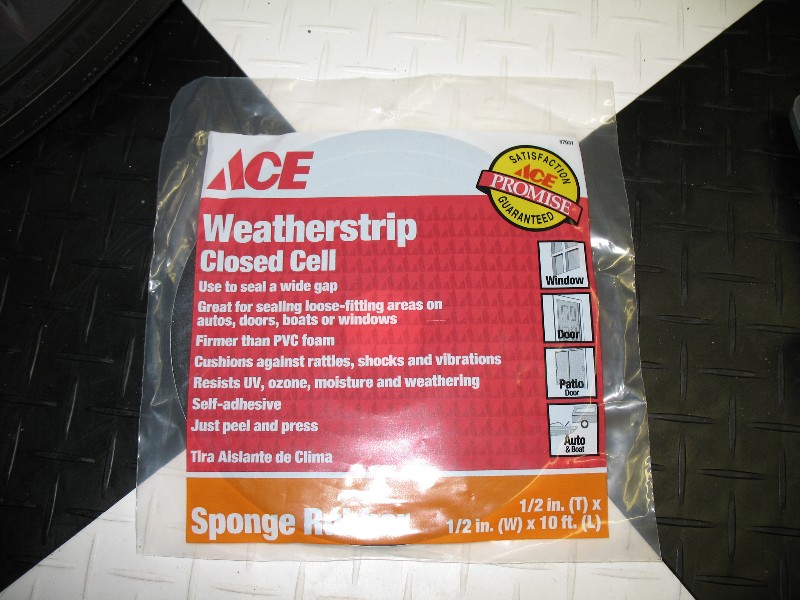
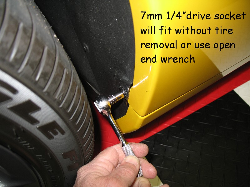
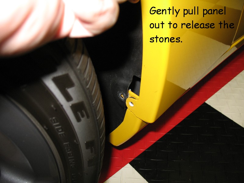
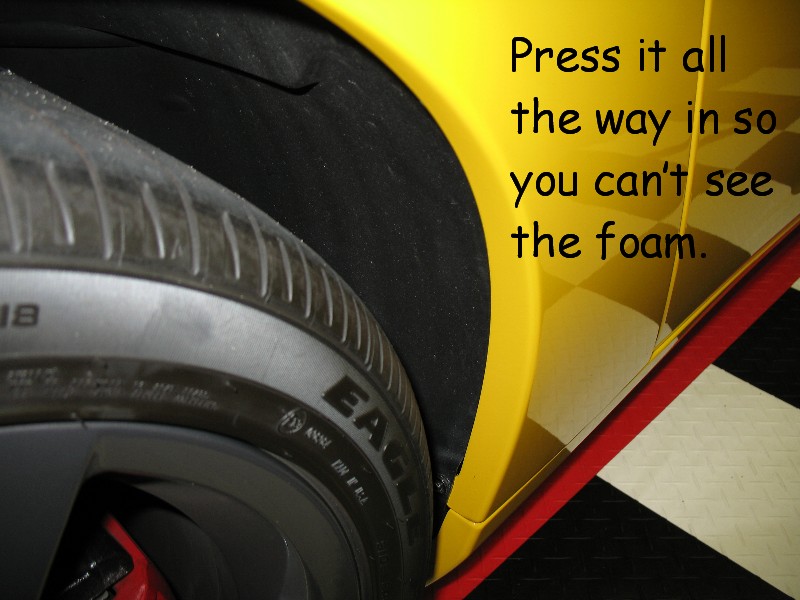
This DYI is designed to stop the dirt and rocks that lodge in the rear fender seam just in front of the rear tire. They are on your car, just go out and look. My main concern is that when detailing or washing the car, one drops into the cloth or wash mitt and I end up dragging a stone across my paint. It appears the problem is due to a large gap in the inner fender liner which allows debris off the tire to enter the inner fender. This is how I fixed it for $5.
I pointed it out to the plant manager when I was at Carlisle, that even a new Z06 with 400 miles had all rocks in the seam. He did not seam to care, and that Z06 was driven by Dave Hill


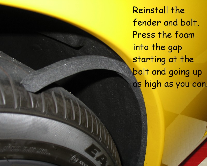
Press the sticky side in first towards the fender
I pointed it out to the plant manager when I was at Carlisle, that even a new Z06 with 400 miles had all rocks in the seam. He did not seam to care, and that Z06 was driven by Dave Hill
Press the sticky side in first towards the fender
03-09-2006, 07:30 AM
#115
Melting Slicks

Member Since: Jan 2005
Location: Looking for a portable X-ray machine
Posts: 2,376
Likes: 0
Received 0 Likes
on
0 Posts
http://www.corvetteforum.net/c5/toom...6alignment.htm
I'm assuming this is for all c6's but just wanted to double check if I was reading this right.
Thank you,
I'm assuming this is for all c6's but just wanted to double check if I was reading this right.
Thank you,
03-19-2006, 11:14 PM
#116
Advanced

Member Since: Mar 2006
Posts: 62
Likes: 0
Received 0 Likes
on
0 Posts
Hello , Does anyone know if you can replace the factory 6 disk changer with the factory navigation ? Do the wiring harnesses work from one to the other ?
If this is possible , does anyone know where to get a factory navigation from ? I really would like to change my cd for the navigation , and would prefer the factory one. I see alot of people on here are using the pioneer AVIC -D1 unit. Ids it really that much better than the factory one ?
Thanks for any help.
03-21-2006, 07:27 PM
#117
Get Some!
Originally Posted by leolufse
For those interested in swapping their 2005 steering wheel to a 2006 steering wheel, I figured out how to get the airbag to work. Besides purchasing the 2006 steering wheel (P.N. 15806311) and the 2006 airbag (P.N. 15782157), you also need to purchase the 2006 clockspring coil kit (P.N. 19133742)
The clockspring pictured here:
has the correct connectors that plug into the back of the 2006 airbag.
Do not attempt to simply swap the connectors by snapping the plugs apart. The shape and type of pin is not compatable with the 2005 plugs. It is a simple task to replace the entire clock spring coil. It plugs into the steering column harness pictured here:
You will need to slightly dremel the lip of the steering consol trim to prevent the 2006 steering wheel from rubbing. You can't see this part of the trim with the steering wheel installed. Another pic:

Futher questions please post.
The clockspring pictured here:
has the correct connectors that plug into the back of the 2006 airbag.
Do not attempt to simply swap the connectors by snapping the plugs apart. The shape and type of pin is not compatable with the 2005 plugs. It is a simple task to replace the entire clock spring coil. It plugs into the steering column harness pictured here:
You will need to slightly dremel the lip of the steering consol trim to prevent the 2006 steering wheel from rubbing. You can't see this part of the trim with the steering wheel installed. Another pic:
Futher questions please post.
http://forums.corvetteforum.com/show...00&forum_id=74
04-02-2006, 07:40 AM
#118
Get Some!
http://forums.corvetteforum.com/show...post1554702320
Originally Posted by Larry B.
Those following my flowmaster threads... I was going to take them off today but decided to do a little research on resonator tips... The stock four tips are full of little holes on the inside wall. These ARE indeed resonator tips. I got two four inch long reducers, drilled a lot of little holes in the small diameter, inserted them small end first into the flowmaster tips.. So now it is a double wall type tip.. The annoying drone is COMPLETLY gone. WOW! I could not believe it.. It still has the same sound ....maybe just a little quieter but by very much. I am a tinkerer and love to do things like this. It made my day when I took the car out for a drive. Incredible that the people that make set ups parts cannot come up with simple solutions.
...Thanks for all of the help and advise... I promise no more flowmaster threads.
...Thanks for all of the help and advise... I promise no more flowmaster threads.
Originally Posted by Larry B.
I got two 2 1/2" - 2" reducers at Pep Boys but any parts place that carries exhaust stuff should have them.. Get the longest size which will be about four inches. Drill about twenty 3/16" holes in the small diameter and cut a slit the full length of the part. Close the diameter up a little and knock it into the tip of the flowmasters small end towards the muffler. They will go in kinda tight so they won't come back out unless you want to take them out. Leave a little bit so you can get them out if you want to.
04-04-2006, 10:10 AM
#119
Get Some!
...http://www.edmunds.com/news/autosho...72/page015.html
2005 Chevrolet Corvette Convertible
What's Special About It?
With an optional power-folding roof, the sixth-generation Corvette rag top ushers in a new era of modernization for the topless Corvette. But there's more to the roadster than just a top that can be lowered at the touch of a button in less than 20 seconds. An extra 15 pounds of sound-deadening material was also added to keep road and wind noise down to a minimum while a corresponding weight reduction in the engine bay assures that no performance was lost in the refinement process. Additional structural bracing is employed to keep cowl shake at bay and the car even passes federal rollover standards without resorting to goofy-looking roll hoops behind the seats. Power comes from the same 400-hp V8 found in the standard coupe, so if you like a little wind in your hair this convertible can serve it up in massive doses. Sales are expected to begin this fall around the same time as the coupe.
04-07-2006, 10:05 AM
#120
Get Some!
Originally Posted by LDB
Though it’s probably safe to assume percentages of MN6 and Z51 are higher on the forum than in overall population, the actual 2005 production numbers are intersting. Let’s try to restrain ourselves from commenting on the lucky so and so percent with such and such option, and simply view it as an indication of how people with free choice, chose to equip their cars.
Z51 41%, Base 35%, F55 24%, MN6 average on all versions 40%, MN6 on Z51 56%, MN6 on base+F55 30%. There were 28% convertibles overall, but the statistics I saw did not break down suspension and transmission by coupe/convertible. Museum delivery was 2%.
The most popular single color was black, 21%, closely followed by silver at 18%. The four different shades of red offered throughout the year totalled 30%, but no individual shade was as high as black or silver. Reds were 15% victory, 9% magnetic, 4% precision, and 2% jewel. Blue was 10%, DSOM 8%, yellow also 8% (6% millenium and 2% velocity), and white 5%.