
Taking out turn signal housing
 11-26-2009, 07:52 PM
#1
Pro

Thread Starter
Member Since: Aug 2009
Location: Fort Lauderdale Florida
Posts: 580
Likes: 0
Received 0 Likes
on
0 Posts

I need to take out my whole turn signal housing on my right side because my bulb shattered inside the housing. Right now I have the access panel removed and I can see there are some screws around the housing but the brake duct cooling pipe is blocking my vision of the whole thing.
Does anyone have any tips or tricks or anything that can help me to get the housing out?
Does anyone have any tips or tricks or anything that can help me to get the housing out?
 11-26-2009, 07:59 PM
#2
Le Mans Master

I replaced my housings with ones from JWMotorsports. There really are only two screws you have to take out to remove the whole housing.
Basically one on each end. The issue, is that one is a torx and the other is a 10MM (I believe it's a 10 MM) screw. The 10MM screw is inthe front corner and a PITA to reach. The brake duct housing gets seriously in the way.
There is also a spring at the top/middle of the housing.. it's easy to remove, and easy to come out. Just remember to hook it back up when replacing the housing.
It's not difficult, it just may take you longer then you expected to remove two screws.
11-26-2009, 09:01 PM
#3
Melting Slicks

Member Since: Oct 2007
Location: Kinston North Carolina
Posts: 2,382
Likes: 0
Received 9 Likes
on
9 Posts

The brake duct is easy to move over out of the way!
------------------------------------------------------
From the Service Manual
------------------------------------------------------
Park/Turn Signal/Side Marker Lamp Replacement Assembly Replacement
Removal Procedure
Raise and suitably support the vehicle. Refer to Lifting and Jacking the Vehicle in General Information.
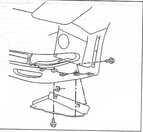
Remove the front fascia lower closeout panel. Refer to Close Out Panel - Front Bumper Fascia Lower in Bumpers.
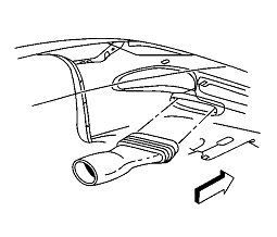
Release the brake caliper cooling duct from the front fascia, then reposition the duct.
Unhook the front turn signal lamp bracket retaining spring from the lamp bracket.
Unhook the lamp bracket retaining spring from the front fascia.
Remove the front turn signal lamp bracket retaining screws.
Disconnect the sockets from the lamp.
Remove the lamp (with the bracket) from the vehicle.
Remove the lamp to bracket retaining screws.
Remove the lamp from the bracket.
Installation Procedure
------------------------------------------------------
From the Service Manual
------------------------------------------------------
Park/Turn Signal/Side Marker Lamp Replacement Assembly Replacement
Removal Procedure
Raise and suitably support the vehicle. Refer to Lifting and Jacking the Vehicle in General Information.
Remove the front fascia lower closeout panel. Refer to Close Out Panel - Front Bumper Fascia Lower in Bumpers.
Release the brake caliper cooling duct from the front fascia, then reposition the duct.
Unhook the front turn signal lamp bracket retaining spring from the lamp bracket.
Unhook the lamp bracket retaining spring from the front fascia.
Remove the front turn signal lamp bracket retaining screws.
Disconnect the sockets from the lamp.
Remove the lamp (with the bracket) from the vehicle.
Remove the lamp to bracket retaining screws.
Remove the lamp from the bracket.
Installation Procedure
Last edited by byronhunter; 11-26-2009 at 09:04 PM.
11-27-2009, 09:35 AM
#4
Tech Contributor
Member Since: Dec 2003
Location: Horncastle Lincolnshire, England
Posts: 19,384
Likes: 0
Received 79 Likes
on
61 Posts
2023 C5 of the Year Finalist - Unmodified
Document ID# 655625
2002 Chevrolet Corvette
________________________________________
Park/Turn Signal/Side Marker Lamp Replacement
Removal Procedure
1. Raise and support the vehicle. Refer to Lifting and Jacking the Vehicle in General Information.
2. Remove the front fascia lower closeout panel.
3. Release the brake caliper cooling duct from the front fascia, and position the duct aside.
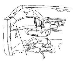
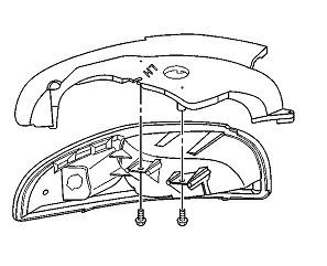
4. Remove the front turn signal lamp bracket retaining spring from the lamp bracket.
5. Remove the lamp bracket retaining spring from the front fascia.
6. Remove the front turn signal lamp bracket retaining screws.
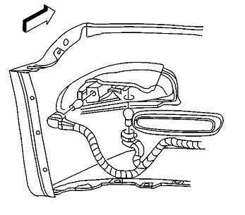
7. Disconnect the sockets from the lamp.
8. Remove the lamp, with the bracket, from the vehicle.
9. Remove the lamp to bracket retaining screws.
10. Remove the lamp from the bracket.
Installation Procedure
1. Install the front park/turn signal and sidemarker lamp into position on the front turn signal lamp bracket.
Notice
Use the correct fastener in the correct location. Replacement fasteners must be the correct part number for that application. Fasteners requiring replacement or fasteners requiring the use of thread locking compound or sealant are identified in the service procedure. Do not use paints, lubricants, or corrosion inhibitors on fasteners or fastener joint surfaces unless specified. These coatings affect fastener torque and joint clamping force and may damage the fastener. Use the correct tightening sequence and specifications when installing fasteners in order to avoid damage to parts and systems.
2. Install the front park/turn signal and sidemarker lamp to bracket retaining screws.
Tighten
Tighten the front park/turn signal and sidemarker lamp to bracket retaining screws to 2 N�m (18 lb in).
3. Install the sockets to the lamp.
4. Install the lamp, with the bracket, to the front fascia.
5. Align the lamp to the opening in the front fascia and hold the lamp firmly in place against the fascia, while installing the front turn signal lamp bracket retaining screws.
Tighten
Tighten the front turn signal lamp bracket retaining screws to 3 N�m (27 lb in).
6. Install the lamp bracket retaining spring to the front fascia.
7. Install the front turn signal lamp bracket retaining spring to the lamp bracket.
8. Position the brake caliper cooling duct to the front fascia and press the duct toward the fascia to secure.
9. Install the front fascia lower closeout panel. Refer to Close Out Panel - Front Bumper Fascia Lower in Bumpers.
2002 Chevrolet Corvette
________________________________________
Park/Turn Signal/Side Marker Lamp Replacement
Removal Procedure
1. Raise and support the vehicle. Refer to Lifting and Jacking the Vehicle in General Information.
2. Remove the front fascia lower closeout panel.
3. Release the brake caliper cooling duct from the front fascia, and position the duct aside.
4. Remove the front turn signal lamp bracket retaining spring from the lamp bracket.
5. Remove the lamp bracket retaining spring from the front fascia.
6. Remove the front turn signal lamp bracket retaining screws.
7. Disconnect the sockets from the lamp.
8. Remove the lamp, with the bracket, from the vehicle.
9. Remove the lamp to bracket retaining screws.
10. Remove the lamp from the bracket.
Installation Procedure
1. Install the front park/turn signal and sidemarker lamp into position on the front turn signal lamp bracket.
Notice
Use the correct fastener in the correct location. Replacement fasteners must be the correct part number for that application. Fasteners requiring replacement or fasteners requiring the use of thread locking compound or sealant are identified in the service procedure. Do not use paints, lubricants, or corrosion inhibitors on fasteners or fastener joint surfaces unless specified. These coatings affect fastener torque and joint clamping force and may damage the fastener. Use the correct tightening sequence and specifications when installing fasteners in order to avoid damage to parts and systems.
2. Install the front park/turn signal and sidemarker lamp to bracket retaining screws.
Tighten
Tighten the front park/turn signal and sidemarker lamp to bracket retaining screws to 2 N�m (18 lb in).
3. Install the sockets to the lamp.
4. Install the lamp, with the bracket, to the front fascia.
5. Align the lamp to the opening in the front fascia and hold the lamp firmly in place against the fascia, while installing the front turn signal lamp bracket retaining screws.
Tighten
Tighten the front turn signal lamp bracket retaining screws to 3 N�m (27 lb in).
6. Install the lamp bracket retaining spring to the front fascia.
7. Install the front turn signal lamp bracket retaining spring to the lamp bracket.
8. Position the brake caliper cooling duct to the front fascia and press the duct toward the fascia to secure.
9. Install the front fascia lower closeout panel. Refer to Close Out Panel - Front Bumper Fascia Lower in Bumpers.