amp meter
 10-24-2007, 04:29 PM
#1
Racer

Thread Starter


I just replaced a blown amp meter on my 66. It reads a little in the negative, but doesn't move when the engine isn't running or when accesories are turned on or off. I don't think it is working. When I started this project, a small cooper u shaped "thing" popped off when I removed the elecrical connector to the amp meter. Can anyone tell me what the u shaped clip is and is it important? Is this part of the assembly and where does it go. Is there a way to check to see if the meter is working? FYI, I'm running about 15 volts to the battery, if the meter is working is it a problem to be in the negative and if so, how can I increase the amps?
Lastly, there is a capacitor on the bottom screw of the plate that holds the amp meter in place. The black wire coming out of the capacitor isn't attached to anything. Can anyone tell me where it should be connected?
Lastly, there is a capacitor on the bottom screw of the plate that holds the amp meter in place. The black wire coming out of the capacitor isn't attached to anything. Can anyone tell me where it should be connected?
 10-24-2007, 04:59 PM
#2
Le Mans Master


The copper U shaped lead coming off the amp gauge is for the capacitor. Check your assembly manual and you will see it illustrated. Generally as you load and unload the the battery (turning on and off the lights etc.), the amp gauge will move. When you start the car, the starter motor turning should draw enough power to move the gauge in the negative range. Jerry
10-24-2007, 07:51 PM
#3
Racer
Thread Starter
Thanks for the reply. I looked in the assembly manual and didn't find what you are referencing. What page are you referring to?
More info on problem, The gauge shows continuity when checking from one post to the other. Also, I have 12 volts at both wires connected to the gauge. The voltage is available with the key off.
The capacitor wire wasn't attached when I started this project. The copper "thing" fell out as I took the electrical connection off the amp meter. Did the black wire coming out of the capacitor at one time connect to the copper "thing"? Where does the copper "thing" attach?
Sorry to drag this out.
10-24-2007, 08:21 PM
#4
Tech Contributor

The capacitor wire wasn't attached when I started this project. The copper "thing" fell out as I took the electrical connection off the amp meter. Did the black wire coming out of the capacitor at one time connect to the copper "thing"? Where does the copper "thing" attach?
Sorry to drag this out.
Sorry to drag this out.
Also, while you are in there, might as well put a 2 amp in-line fuse in the Amp gauge circuit to protect it from blowing. Just insert a 2 amp fuse into the circuit between one of the terminals of the amp gauge, and the wire that connects to that terminal.
Here's a pic, including the capacitor
 10-24-2007, 08:40 PM
#5
Burning Brakes

The copper thing I think is connect to one of the terminals of the meter, if I remember it is sorta just held there by the terminal plug, it slides in with the terminal....the other end (maybe just the body of the cap) goes to ground via the console. WARNING!!! I am not looking at a diagram or a car so this is just from my weak memory, verify this before you hook it up.
The Cap should have no real affect on the gauge reading, it is there to reduce electrical noise and will maybe stabilize the gauge reading slightly...I don't run one in my 65 but radio noise is of no concern for me.
The gauge itself is a shunt type meter. It is really a sensitive voltage meter. Both terminals are tied to 12v one at the starter the other at the horn relay. The gauge measures the minor differences in voltage between those two points and report it as current through the primary charge wire that also connects the starter to the horn relay. If your gauge does not move when you turn the key (it should go really negative) then either gauge is bad or it is connected wrong or there is some other wiring change (ie a one wire alternator or heavy gauge bypass)
One simple way to test the gauage is with a normal AAA,AA,C,D cell battery. If you put the battery between the gauge terminals the gauge should move one way or the other, reverse the battery and it will go the other way if not the gauge is bad. Since you have 12 volts at both plug terminals (I assume that is read with the gauge unplugged) then you probably have the wiring right, so unless you have a bypass wire or some other oddity the gauge is probably bad.
One thing I note you say you have 15V at the battery, this is pretty high. Do you have some non stock parts in the charging system?
Battery voltage is usually like 13.8, and maybe 14.3 to 14.7 with the alternator charging....regardless of the actual voltage the gauge should still operate (it might not be totally accurate but they never are) but I would wonder why if you have 15 at the battery you don't have 15 at the gauge????
Last edited by macdarren; 10-24-2007 at 08:50 PM.
10-24-2007, 08:49 PM
#6
Burning Brakes
Jeff, that is a great photo....I don't know how you guys do that mine are always dark or blurred. I notice in the picture what looks like a bracket holding what I think is the column wiring harness? Is that so? I have never seen that on mine and always wondered how that harness is supposed to be retained....I usually used zip ties but I know it has a little push pin on it but never where it was supposed to go....
Is the fuse there to save the gauge or prevent a short from melting a wire?
Is the fuse there to save the gauge or prevent a short from melting a wire?
Last edited by macdarren; 10-24-2007 at 08:52 PM.
10-24-2007, 09:10 PM
#7
Tech Contributor
Jeff, that is a great photo....I don't know how you guys do that mine are always dark or blurred. I notice in the picture what looks like a bracket holding what I think is the column wiring harness? Is that so? I have never seen that on mine and always wondered how that harness is supposed to be retained....I usually used zip ties but I know it has a little push pin on it but never where it was supposed to go....
Is the fuse there to save the gauge or prevent a short from melting a wire?
Is the fuse there to save the gauge or prevent a short from melting a wire?
Bracket - ??? Not sure what you are referencing. Can you guide me to the area of my picture you are looking at? The main harness has 2 white pins integrated into the protective wrapping, which snap into the top rear of the cluster into 2 little holes. The new harness at the column comes with a push pin which is slid into a slot in the column connector. However, that slot is REALLY supposed to slide over a metal clip that is in the top side of your column. If that metal clip is missing, then that push pin would snap into the hole in the column left by that clip. On my car, my metal clip was still intact so I removed the plastic pin and slid my column connector onto the metal clip.
Fuse - MagicV8 told me about the fuse. It is there to protect the gauge since the gauge is otherwise at risk, damages easily, and is a bear to replace on a factory A/C car. In my case, after having my gauges rebuilt by Jason, and replacing all of my wiring, my voltage regulator developed stuck points which fried my amp gauge. So after Jason rebuilt my Amp gauge again, I added the fuse.
10-24-2007, 11:43 PM
#8
Racer
Thread Starter
Wow, to use and old cliche, a picture is worth a thousand words! Thank you so much. I resoldier the cooper "thing" and it reinstalled everything. Still no meter reading.
I will try dry cell battery check tomorrow to see if gauge moves in either direction. If it doesn't move, I'll sent it back to the person I purchased it from.
I was thinking the charging volts at the battery should be 15 volts so that is what I set the regulator. I'll go back and readjust it. Thanks!
Since we are under the dash with sore back and neck, can anyone tell me where the capacitor that is mounted on the right side of the steering column support goes. The black wire coming out of this capacitor has approximately 1" long copper end piece.
10-24-2007, 11:59 PM
#9
Tech Contributor
 10-25-2007, 12:43 AM
#10

original76...You were correct in checking for voltage at both connectors to the ammeter, but did you do this test with the connectors disconnected from the gauge, as macdarren suggested?
10-25-2007, 01:39 AM
#11
Burning Brakes

Give us a little more detail on "adjusting the volt regulator." I am suspicious. Pls do the aaa aa bat trick to see if the gage is ok.
IMHO get a solid state volt reg and not worry about adjusting the regulator.
brgds
rene
IMHO get a solid state volt reg and not worry about adjusting the regulator.
brgds
rene
 10-25-2007, 01:33 PM
#13
Racer
Thread Starter
Checked the meter with a D battery. The meter went both positive and negative so I'm assuming the gauge is OK. The only difference, I see between the new gauge and old is the new has two posts and the old has three. Two post had the terminals and the other just a lock washer and nut. Thinking the third post was a ground I made sure the gauge was grounded and still didn't work. However, I could only ground the outside of the gauge housing. Might be the ground is internal. I'll ask seller if the other amp meters is has have three posts. Lastly, I measured the voltage with the wiring harness disconnected. When I get this solved, I'll let you all know.
There is a screw in the voltage regulator that adjust charging volts. This is what I used to adjust battery voltage. Want to stay stock if possible so probably will not go solid state.
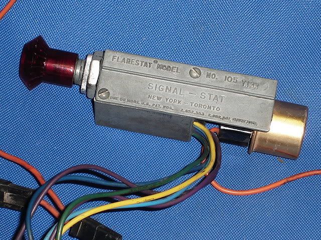
Another subject. While looking for the brake capacitor connections, that isn't anywhere to be found, I found a orange wire that isn't connected. The wire goes to a "flarestat" that is above the emergency brake handle. I looked in the assembly manual and didn't find it. Can anyone tell me what the flarestat does and where the orange wire connects?
As always, advance thanks for any assistence.
There is a screw in the voltage regulator that adjust charging volts. This is what I used to adjust battery voltage. Want to stay stock if possible so probably will not go solid state.
Another subject. While looking for the brake capacitor connections, that isn't anywhere to be found, I found a orange wire that isn't connected. The wire goes to a "flarestat" that is above the emergency brake handle. I looked in the assembly manual and didn't find it. Can anyone tell me what the flarestat does and where the orange wire connects?
As always, advance thanks for any assistence.
 10-25-2007, 10:38 PM
#15
The only difference, I see between the new gauge and old is the new has two posts and the old has three. Two post had the terminals and the other just a lock washer and nut. Thinking the third post was a ground I made sure the gauge was grounded and still didn't work. However, I could only ground the outside of the gauge housing. Might be the ground is internal. I'll ask seller if the other amp meters is has have three posts.
10-26-2007, 08:57 PM
#16
Team Owner


Member Since: Oct 2000
Location: Washington Michigan
Posts: 38,899
Received 1,857 Likes
on
1,100 Posts

The battery gauge only has two (spade) terminals for the connector; the threaded stud and nut is what holds the gauge to the cluster rear panel. 
The following users liked this post:
1960 (03-27-2022)
10-27-2007, 12:25 AM
#17
Thanks, John, I guess I should rephrase my reply. My new battery gauge does not have the third threaded stud that retains the gauge to the cluster.
10-27-2007, 12:41 AM
#18
Burning Brakes
Member Since: Dec 2002
Location: Hasbrouck Heights NJ
Posts: 1,062
Likes: 0
Received 4 Likes
on
3 Posts
Fuse - MagicV8 told me about the fuse. It is there to protect the gauge since the gauge is otherwise at risk, damages easily, and is a bear to replace on a factory A/C car. In my case, after having my gauges rebuilt by Jason, and replacing all of my wiring, my voltage regulator developed stuck points which fried my amp gauge. So after Jason rebuilt my Amp gauge again, I added the fuse.
10-27-2007, 01:05 AM
#19
Tech Contributor
 10-27-2007, 01:18 AM
#20