
Connecting wideband via EGR or A/C Pressure in HP Tuners
 05-15-2007, 03:16 PM
#1
Melting Slicks

Thread Starter


I have gotten a few people email me about wiring a wideband up for logging using the AC pressure sensor. If I do an elaborate How-To on this can it be made into a sticky? I have to go through all the steps time and time again for people on this. I think a lot of people get into HPtuners without purchasing the EIO cable and dont want to pay for the upgrade after they buy a wideband. I was just wondering if I could get a sticky made out of this. I need someone to host it as well. 
So here it goes... With Pics!
1. First thing to do is track down the AC Pressure sensor. It is located on the passenger side right up in front of the coolant reservoir. Here is a picture of what you are looking for.
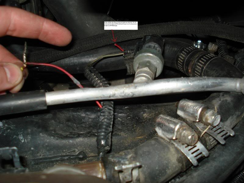
2. Now you have three choices on how to do this next step.
1.* The easiest way to do this is to install a switch in this wire you just cut. This way you can switch the output on the wire from the wideband to the AC when you arent tuning. It will take a 3pole switch that has 2 inputs and one output.
2.* If you dont want to run AC just wire the wideband in and leave the sensor unplugged. This one is not for me, AC is a must!
3.* Install quick connect ends where you can unplug the wideband and plug the AC Sensor back up.
3. Of course you will have to wire the Wideband as well. Once everything is wired up check to make sure the wideband is working properly on the gauge display. Once operation is correct we can go on to getting this thing to read into HPtuners.
4. This is very simple to do it sounds harder than it really is. Here it is step by step.
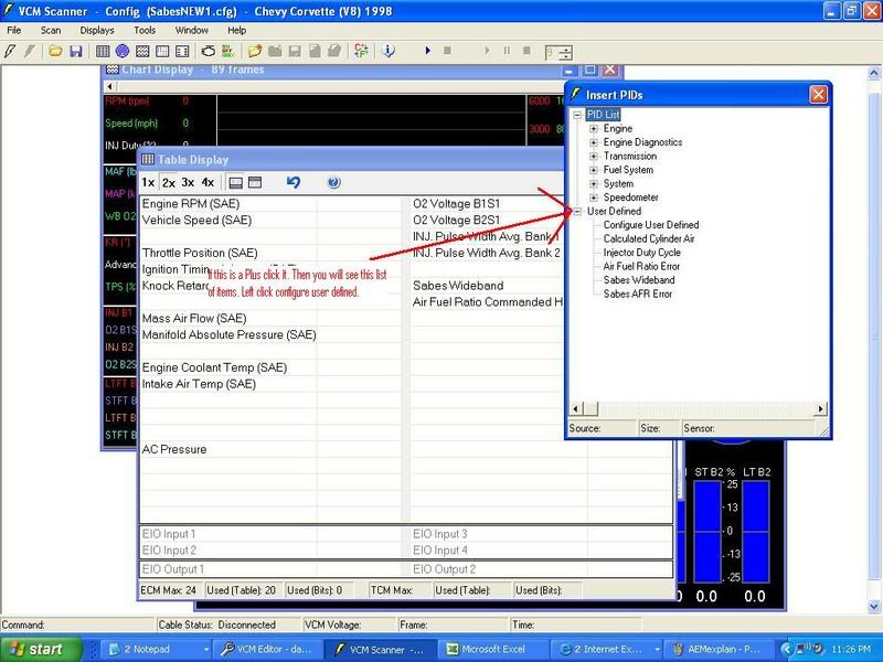
1.- Open VCM Scanner
2.- Open the Table Display
3.- Right click the table
4.- Left click insert
5.- Down at the bottom you will see User Defined if there is a + sign next to it click the + sign and you will see configure user defined.
6.- Double Left click configure user defined
Here is a pic
7.- Now click one of the undefined labels and insert a name for your wideband.
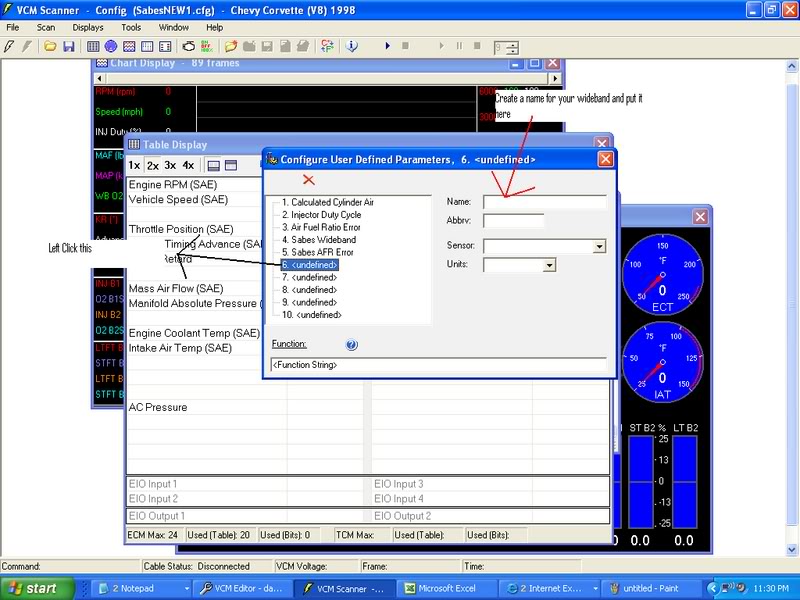
8.- Now we need to input the function string that will take the voltage coming from the wideband output and convert it to AFR. At the bottom of this screen you will see a function line. Enter ([PID. 7101]/.5)+10, you will notice mine is 9.8... we will get to this in a minute for now just put 10.
9.- Now the reason my formula is 9.8 is because of voltage drop. When doing some researching I figured out that my wideband was reading .2 different on my HPtuners than the gauge display was showing. So using the formula I basically calibrated my laptop to read the same as my gauge. So you need to scan the car and see if there is any difference, if there is adjust it the way I did.
10. Now lets open the scanner, connect to the car and scan to ensure the PID is working. If you have a switch installed make sure you have it on the wideband. If everything is working good lets move on to creating a histogram.
Creating the Histogram for the wideband
1.- Now that we have created the function already this part is very simple. Open the Scanner, open the histogram display.
2.- To the right of the number 8 you will see a configure button. Click that.
3.- The easiest way to do this is to use the wideband configuration thats default on the scanner. Click the wideband input, I am wanting to think its the #6. I will post pics of this setup tonight.
4.- You will then see how the wideband is default setup. If you look where it says sensor you will see that next to the sensor it says air fuel ratio. To the right of that you will see PID:, Click next to where it says PID:.
5.- You should see the custom PID we made earlier for the wideband. It will be listed under the user configured and will be named the name you created earlier. Now double click the custom pid you created and hit the floppy disk in the top left corner to commit the changes.
6.- Do another scan and ensure everything is working properly.
Its back to work for me, but next we tackle creating an air fuel ratio %error histogram. Pics coming soon!
So here it goes... With Pics!
1. First thing to do is track down the AC Pressure sensor. It is located on the passenger side right up in front of the coolant reservoir. Here is a picture of what you are looking for.
2. Now you have three choices on how to do this next step.
1.* The easiest way to do this is to install a switch in this wire you just cut. This way you can switch the output on the wire from the wideband to the AC when you arent tuning. It will take a 3pole switch that has 2 inputs and one output.
2.* If you dont want to run AC just wire the wideband in and leave the sensor unplugged. This one is not for me, AC is a must!
3.* Install quick connect ends where you can unplug the wideband and plug the AC Sensor back up.
3. Of course you will have to wire the Wideband as well. Once everything is wired up check to make sure the wideband is working properly on the gauge display. Once operation is correct we can go on to getting this thing to read into HPtuners.
4. This is very simple to do it sounds harder than it really is. Here it is step by step.
1.- Open VCM Scanner
2.- Open the Table Display
3.- Right click the table
4.- Left click insert
5.- Down at the bottom you will see User Defined if there is a + sign next to it click the + sign and you will see configure user defined.
6.- Double Left click configure user defined
Here is a pic
7.- Now click one of the undefined labels and insert a name for your wideband.
8.- Now we need to input the function string that will take the voltage coming from the wideband output and convert it to AFR. At the bottom of this screen you will see a function line. Enter ([PID. 7101]/.5)+10, you will notice mine is 9.8... we will get to this in a minute for now just put 10.
9.- Now the reason my formula is 9.8 is because of voltage drop. When doing some researching I figured out that my wideband was reading .2 different on my HPtuners than the gauge display was showing. So using the formula I basically calibrated my laptop to read the same as my gauge. So you need to scan the car and see if there is any difference, if there is adjust it the way I did.
10. Now lets open the scanner, connect to the car and scan to ensure the PID is working. If you have a switch installed make sure you have it on the wideband. If everything is working good lets move on to creating a histogram.
Creating the Histogram for the wideband
1.- Now that we have created the function already this part is very simple. Open the Scanner, open the histogram display.
2.- To the right of the number 8 you will see a configure button. Click that.
3.- The easiest way to do this is to use the wideband configuration thats default on the scanner. Click the wideband input, I am wanting to think its the #6. I will post pics of this setup tonight.
4.- You will then see how the wideband is default setup. If you look where it says sensor you will see that next to the sensor it says air fuel ratio. To the right of that you will see PID:, Click next to where it says PID:.
5.- You should see the custom PID we made earlier for the wideband. It will be listed under the user configured and will be named the name you created earlier. Now double click the custom pid you created and hit the floppy disk in the top left corner to commit the changes.
6.- Do another scan and ensure everything is working properly.
Its back to work for me, but next we tackle creating an air fuel ratio %error histogram. Pics coming soon!
Last edited by 95BlueBomber; 05-21-2007 at 02:36 PM.
 05-16-2007, 10:31 AM
#2
Supporting Tuner
Member Since: Mar 2006
Location: Houston TX
Posts: 1,311
Likes: 0
Received 0 Likes
on
0 Posts
Cruise-In VIII Veteran
St. Jude Donor '06-'07
I would like to see something like this posted as a sticky. It would be very beneficial to everyone. I hope you can get this done. 
05-16-2007, 11:12 AM
#3
Melting Slicks
Thread Starter
05-16-2007, 01:33 PM
#4
Supporting Tuner
Member Since: Mar 2006
Location: Houston TX
Posts: 1,311
Likes: 0
Received 0 Likes
on
0 Posts
Cruise-In VIII Veteran
St. Jude Donor '06-'07
I would say just go ahead and work on it and then PM it to a moderator and see what they have to say. You can also post it in here as well even if it doesn't become a sticky it will just go into the archives and still be searchable. Good luck.
05-17-2007, 12:26 AM
#5
Melting Slicks
I wrote this a while back just for personal information. This is based on HP Tuners.
UPDATED
Reading a Wideband through the EGR or A/C Pressure Switch
EGR
• The EGR wire is located at Pin 55 on the Blue connector of the PCM (NOTE: on the 97-98 Corvettes this will be Pin 9 on the Blue connector).
• On vehicles that come with an EGR (Camaro's, etc.), there will be a Brown wire at Pin 55, it is designated “EGR Pintle Position Sensor Signal” in a pinout schematic.
• If your vehicle did not come equipped with an EGR (Corvette), there will not be a wire and the schematic will say "Not Used". Just add a wire to the PCM at Pin 55 (or 9), everything still works the same. I went to a junkyard and found a plug under the hood of a GM vehicle with the same type of ends as the PCM wires. Click here for instructions on how to gain access to your PCM.
• Connect the Wideband 02 wire with the 0-5v output to the EGR wire at Pin 55(or 9). This may be all you need to do with some widebands, some others require a ground. Check the wiring schematic for your specific unit.
A/C Pressure Switch
• There are 3 wires connected to the A/C Pressure sensor. The Red wire with Black stripe that is going to the PCM is the one we want to use. You can go to a junkyard and find another connector to plug into this so you can switch back and forth or you can buy a Maintain switch that, when you switch it one way it reads from the A/C sensor and when switched the other way, it reads from the Wideband O2 output wire. Either way will work fine, so that you can easily put it back to normal when you are done tuning.
HP Tuner Scanner
• Now that the wiring is done, you need to set it up in HP Tuners. You will need some information on your specific wideband that will be in the widebands paperwork. You will have to set up a formula to change the voltage (0-5v) into your AFR wideband reading. It will look like this:
VOLTS / (VOLTAGE RANGE/DEVICE RANGE) + (MINIMUM VALUE OF DEVICE READING) = AFR
VOLTS = the voltage that the wideband 02 sensor is putting out to the EGR wire
VOLTAGE RANGE = typically 5v (0-5v), some people use the narrowband 02 input (not recommended) which is 1v (0-1v)
DEVICE RANGE = the range your wideband is set to read. If the wideband is set to read from 10 – 20 AFR, then the range will be 10. If set to read from 8 – 22 AFR, the range will be 14, etc.
MINIMUM VALUE OF DEVICE READING = the lowest number that your wideband is set to read. In the above examples, it would be 10 for the first example, and 8 for the second.
I am using a PLX SM-AFR 250 that is set to read AFR from 10-20, so I will use it for my example. The formula will be:
VOLTS / (5/10) + 10 = AFR or,
(VOLTS / .5) + 10 = AFR
• Since HP Tuners Scanner will be using the EGR or AC Pressure switch to get its readings from, we need to add that into the formula. The PID for the EGR on LS1 based cars is PID.2811 (EGR Position). Now the formula reads like this:
([PID.2811]/.5)+10 = AFR
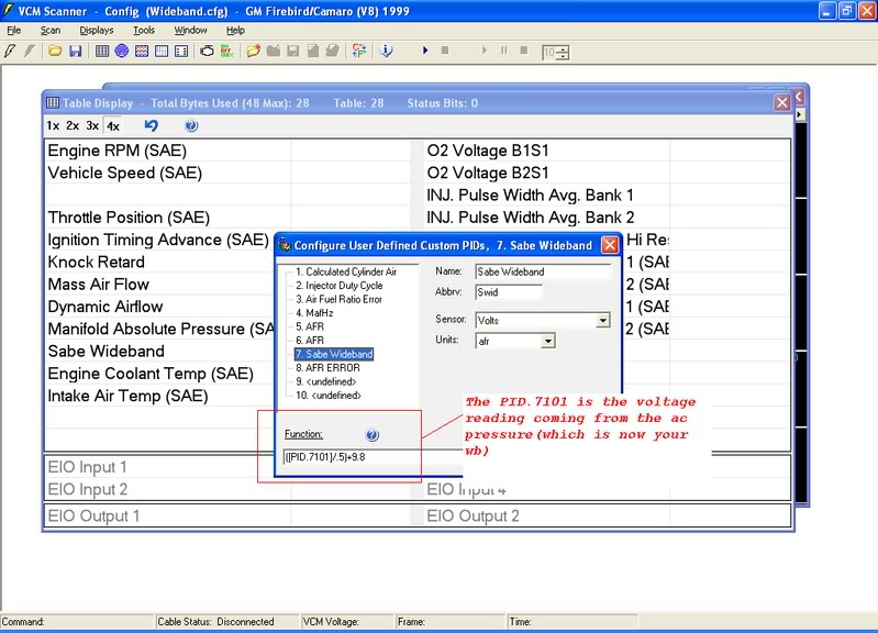
• The formula for the A/C Pressure switch is the same, you will just have to change the PID to PID.7101.
([PID.7101]/.5)+10 = AFR
Custom PID
• Open Table Display in VCM Scanner
• Right click any blank line and choose Insert
• This will open the Insert PIDs display
• Here you will see PID List, AUX Input List and User Defined. Click the + next to User Defined to open the drop down list
• Double click Configure User Defined to open Configure User Defined Parameters
• Click on one of the numbers with <undefined> next to it
• For Name:, put the name of your choice, say, Air Fuel Ratio
• For Abbrv:, put AFR
• For Sensor:, open the drop down box and choose "None"
• For Units:, open the drop down box and choose ":1"
• Under Function:, insert your formula. For EGR it is ([PID.2811]/.5)+10
• If you are using the A/C Pressure switch, use the formula: ([PID.7101]/.5)+10
• That’s it, just click the Up Arrow to commit changes, then click the X at the top right to close the box and click the Save icon on the Histogram Configuration page.
• To make a custom PID for AFR % Error make your way back to the Configure User Defined parameters page. There will already be an Air Fuel Ratio Error PID. Open it and look at the information in the Function box.
• Copy this formula EXACTLY. It will look like this:
100*([SENS.120]-[SENS.121])/[SENS.121]
• Since SENS.120 is the AFR SENSOR we want to create a new Custom PID and substitute our new formula in place of SENS.120, then enter this into the Function box. Now it will look like this:
100*((([PID.2811]/.5)+10)-[SENS.121])/[SENS.121] or
100*((([PID.7101]/.5)+10)-[SENS.121])/[SENS.121] for the A/C Pressure switch. If you have trouble, double check all your parenthesis. It is best to copy/paste this formula.
• On this Custom PID, give it a name, use AFR%Error for the Abbrv, leave Sensor blank, and use % for Units.
• Now, you can change the information in your VE and MAF Histograms to use the custom PIDs that you just made.
• ATTENTION: In Editor (Engine/General), you have to enable EGR. Also, don’t forget that each of these below will have to be logged in Table Display:
- EGR Position, if your are using EGR Pinout 55 (or 9). Located: (PID List/Engine/Emissions/EGR Position (V))
- A/C Pressure, if you are using the A/C Pressure switch. Located: (PID List/System/AC/AC Pressure (V))
- AFR
- AFR % Error
- AFR Commanded
UPDATED
Reading a Wideband through the EGR or A/C Pressure Switch
EGR
• The EGR wire is located at Pin 55 on the Blue connector of the PCM (NOTE: on the 97-98 Corvettes this will be Pin 9 on the Blue connector).
• On vehicles that come with an EGR (Camaro's, etc.), there will be a Brown wire at Pin 55, it is designated “EGR Pintle Position Sensor Signal” in a pinout schematic.
• If your vehicle did not come equipped with an EGR (Corvette), there will not be a wire and the schematic will say "Not Used". Just add a wire to the PCM at Pin 55 (or 9), everything still works the same. I went to a junkyard and found a plug under the hood of a GM vehicle with the same type of ends as the PCM wires. Click here for instructions on how to gain access to your PCM.
• Connect the Wideband 02 wire with the 0-5v output to the EGR wire at Pin 55(or 9). This may be all you need to do with some widebands, some others require a ground. Check the wiring schematic for your specific unit.
A/C Pressure Switch
• There are 3 wires connected to the A/C Pressure sensor. The Red wire with Black stripe that is going to the PCM is the one we want to use. You can go to a junkyard and find another connector to plug into this so you can switch back and forth or you can buy a Maintain switch that, when you switch it one way it reads from the A/C sensor and when switched the other way, it reads from the Wideband O2 output wire. Either way will work fine, so that you can easily put it back to normal when you are done tuning.
HP Tuner Scanner
• Now that the wiring is done, you need to set it up in HP Tuners. You will need some information on your specific wideband that will be in the widebands paperwork. You will have to set up a formula to change the voltage (0-5v) into your AFR wideband reading. It will look like this:
VOLTS / (VOLTAGE RANGE/DEVICE RANGE) + (MINIMUM VALUE OF DEVICE READING) = AFR
VOLTS = the voltage that the wideband 02 sensor is putting out to the EGR wire
VOLTAGE RANGE = typically 5v (0-5v), some people use the narrowband 02 input (not recommended) which is 1v (0-1v)
DEVICE RANGE = the range your wideband is set to read. If the wideband is set to read from 10 – 20 AFR, then the range will be 10. If set to read from 8 – 22 AFR, the range will be 14, etc.
MINIMUM VALUE OF DEVICE READING = the lowest number that your wideband is set to read. In the above examples, it would be 10 for the first example, and 8 for the second.
I am using a PLX SM-AFR 250 that is set to read AFR from 10-20, so I will use it for my example. The formula will be:
VOLTS / (5/10) + 10 = AFR or,
(VOLTS / .5) + 10 = AFR
• Since HP Tuners Scanner will be using the EGR or AC Pressure switch to get its readings from, we need to add that into the formula. The PID for the EGR on LS1 based cars is PID.2811 (EGR Position). Now the formula reads like this:
([PID.2811]/.5)+10 = AFR
• The formula for the A/C Pressure switch is the same, you will just have to change the PID to PID.7101.
([PID.7101]/.5)+10 = AFR
Custom PID
• Open Table Display in VCM Scanner
• Right click any blank line and choose Insert
• This will open the Insert PIDs display
• Here you will see PID List, AUX Input List and User Defined. Click the + next to User Defined to open the drop down list
• Double click Configure User Defined to open Configure User Defined Parameters
• Click on one of the numbers with <undefined> next to it
• For Name:, put the name of your choice, say, Air Fuel Ratio
• For Abbrv:, put AFR
• For Sensor:, open the drop down box and choose "None"
• For Units:, open the drop down box and choose ":1"
• Under Function:, insert your formula. For EGR it is ([PID.2811]/.5)+10
• If you are using the A/C Pressure switch, use the formula: ([PID.7101]/.5)+10
• That’s it, just click the Up Arrow to commit changes, then click the X at the top right to close the box and click the Save icon on the Histogram Configuration page.
• To make a custom PID for AFR % Error make your way back to the Configure User Defined parameters page. There will already be an Air Fuel Ratio Error PID. Open it and look at the information in the Function box.
• Copy this formula EXACTLY. It will look like this:
100*([SENS.120]-[SENS.121])/[SENS.121]
• Since SENS.120 is the AFR SENSOR we want to create a new Custom PID and substitute our new formula in place of SENS.120, then enter this into the Function box. Now it will look like this:
100*((([PID.2811]/.5)+10)-[SENS.121])/[SENS.121] or
100*((([PID.7101]/.5)+10)-[SENS.121])/[SENS.121] for the A/C Pressure switch. If you have trouble, double check all your parenthesis. It is best to copy/paste this formula.
• On this Custom PID, give it a name, use AFR%Error for the Abbrv, leave Sensor blank, and use % for Units.
• Now, you can change the information in your VE and MAF Histograms to use the custom PIDs that you just made.
• ATTENTION: In Editor (Engine/General), you have to enable EGR. Also, don’t forget that each of these below will have to be logged in Table Display:
- EGR Position, if your are using EGR Pinout 55 (or 9). Located: (PID List/Engine/Emissions/EGR Position (V))
- A/C Pressure, if you are using the A/C Pressure switch. Located: (PID List/System/AC/AC Pressure (V))
- AFR
- AFR % Error
- AFR Commanded
Last edited by 'VETTE PHASE; 05-19-2013 at 12:37 PM.
05-17-2007, 06:46 AM
#6
Supporting Tuner
Member Since: Mar 2006
Location: Houston TX
Posts: 1,311
Likes: 0
Received 0 Likes
on
0 Posts
Cruise-In VIII Veteran
St. Jude Donor '06-'07
I think that's a pretty good start. I agree with 95BlueBomber about getting something like this posted as a sticky where people can still contribute after he posts his information. I think this could turn into a very useful tool.


 05-17-2007, 09:30 AM
#8
Melting Slicks
Thread Starter
200c-5,
That is basically the information I wanted to get made into a sticky, I have been working on getting that together with pics. Most people do not want to mess with the EGR input on the PCM. Its too much work when its as easy as putting the voltage to the AC Pressure sensor. I have almost got this info done, I will post as soon as it is complete.
That is basically the information I wanted to get made into a sticky, I have been working on getting that together with pics. Most people do not want to mess with the EGR input on the PCM. Its too much work when its as easy as putting the voltage to the AC Pressure sensor. I have almost got this info done, I will post as soon as it is complete.
05-17-2007, 10:37 PM
#9
Melting Slicks
200c-5,
That is basically the information I wanted to get made into a sticky, I have been working on getting that together with pics. Most people do not want to mess with the EGR input on the PCM. Its too much work when its as easy as putting the voltage to the AC Pressure sensor. I have almost got this info done, I will post as soon as it is complete.
That is basically the information I wanted to get made into a sticky, I have been working on getting that together with pics. Most people do not want to mess with the EGR input on the PCM. Its too much work when its as easy as putting the voltage to the AC Pressure sensor. I have almost got this info done, I will post as soon as it is complete.
Now, check it out.
05-17-2007, 10:57 PM
#10
Drifting

Member Since: Sep 2005
Location: Home Southern Maine
Posts: 1,258
Likes: 0
Received 0 Likes
on
0 Posts
St. Jude Donor '08
I am doing something similiar with EFI Live, only using the EGR pinouts for 5V power and ground to feed my Autometer Fuel Pressure sending unit, and using the EGR sensor voltage to report fuel Pressure.
Works great.
Works great.
05-19-2007, 04:13 PM
#14
Drifting
Member Since: Sep 2005
Location: Home Southern Maine
Posts: 1,258
Likes: 0
Received 0 Likes
on
0 Posts
St. Jude Donor '08
Here are some pics if you need them

Above PCM 18 ga connectors 50 cents each

Example of how to put the connector in. Puncture the rubber seal and insert the new pin. This photo was for the valet/cos5 pinout for EFI Live (Red Connector Pin 56).
Above PCM 18 ga connectors 50 cents each
Example of how to put the connector in. Puncture the rubber seal and insert the new pin. This photo was for the valet/cos5 pinout for EFI Live (Red Connector Pin 56).
05-19-2007, 04:21 PM
#15
Supporting Tuner
Member Since: Mar 2006
Location: Houston TX
Posts: 1,311
Likes: 0
Received 0 Likes
on
0 Posts
Cruise-In VIII Veteran
St. Jude Donor '06-'07

 05-21-2007, 09:01 AM
#19
Supporting Tuner
Member Since: Mar 2006
Location: Houston TX
Posts: 1,311
Likes: 0
Received 0 Likes
on
0 Posts
Cruise-In VIII Veteran
St. Jude Donor '06-'07
Cool. I think this will be a big help for those just starting out with this. Thanks for taking the time to write this up guys. Glad I could help getting it posted up for you.