
Wiring Wide Band into EGR or AC Output
 09-21-2006, 01:35 PM
#1
Le Mans Master

Thread Starter

This is in order to monitor the wideband output without having the enhanced I/O interface for HP Tuners 2.1.x. The reson being is I got my serial interface just prior to them releasing the USB/MPVI cable. So to upgrade to the MPVI Pro is another $200.
I know the Camaro guys have been able to re-route the wires going to the EGR to the wideband and have met with good success. There is plenty of information on how to create the custom PID to make it look exactly like a wideband to HPT. The problem is there is no EGR on the vette. Some guys have also used the output from the AC pressure sensor to tie the wideband into. The problem with that is I still have my AC intact and it's not going anywhere anytime soon and I don't want to affect the AC performance or pressure cutoff function.
I'm not sure if any vette guys have been successful in this. So I'm either looking for another sensor with 0-5V output that I don't need or I have been thinking of investigating whether there are wires or blank pins on the PCM to insert wires into for the EGR. Then I could enable it in the tune and wire it into an LC-1.
I guess I'm more thinking outloud. I haven't looked into this yet and my online Helms manual is down at the moment. I guess I'm just looking for others thoughts on this.
Last edited by 5 Liter Eater; 09-27-2006 at 09:47 AM.
 09-21-2006, 03:26 PM
#3
Le Mans Master
Thread Starter
Makes sense. Just a toggle switch to redirect the output between the WB and AC sensor.
Do you have any additional info? Like the wire you tapped into and/or how you wired/grounded the WB?
Do you have any additional info? Like the wire you tapped into and/or how you wired/grounded the WB?
09-21-2006, 04:10 PM
#4
Melting Slicks


I believe the wire is red with a black stripe. Then you must setup a PID in hp tuners scanner. In order to setup the PID you must find what sensor is your AC pressure let me take some screenshots and I will post them.
As far as the ground goes, I believe mine is grounded on the drivers side frame rail.
As far as the ground goes, I believe mine is grounded on the drivers side frame rail.
09-21-2006, 04:22 PM
#5
Melting Slicks
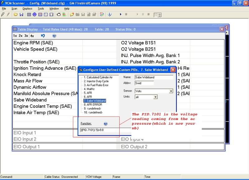
Hope this helps... The numbers aren't just thrown together. The 9.8 for me may be 10 for you. The best way to test this is to go to a dyno and compare the results and adjust the number accordingly. I found that mine was .2 off. Its very very close now. You can do this by watching the gauge as well, just not as accurate. Let me know if I can do anything else to help!
09-22-2006, 09:49 AM
#7
Le Mans Master
Thread Starter
I am wondering where that equation came from though. In the HPT Help file it says that the LC-1 PID should be volts/0.3324+7.35 which I really don't understand either. I realize this is different but I am trying to understand the equation.
A snipit from this thread has your same equation.
http://www.hptuners.com/forum/showth...t=Wideband+EGR
"For the AEM guage the formula would be
=(EGR_Volts/0.5)+10"
A snipit from this thread has your same equation.
http://www.hptuners.com/forum/showth...t=Wideband+EGR
"For the AEM guage the formula would be
=(EGR_Volts/0.5)+10"
09-22-2006, 10:16 AM
#8
Melting Slicks
Originally Posted by 5 Liter Eater
I am wondering where that equation came from though. In the HPT Help file it says that the LC-1 PID should be volts/0.3324+7.35 which I really don't understand either. I realize this is different but I am trying to understand the equation.
A snipit from this thread has your same equation.
http://www.hptuners.com/forum/showth...t=Wideband+EGR
"For the AEM guage the formula would be
=(EGR_Volts/0.5)+10"
A snipit from this thread has your same equation.
http://www.hptuners.com/forum/showth...t=Wideband+EGR
"For the AEM guage the formula would be
=(EGR_Volts/0.5)+10"
09-22-2006, 10:22 AM
#9
Le Mans Master
Thread Starter
I don't have an LC-1 just yet. :o I'm just getting my ducks in a row before I do. I wanted to be sure I could use the AC or EGR to log it via HPT first.
09-22-2006, 10:41 AM
#10
Melting Slicks
I know you can but the equation will be a little different. I myself like the AEM gauge. You have no calibrating to do and you can mount the gauge in a pod. I put mine in the ashtray. Let me know when you get your setup and I will email you some pictures of my install and how to wire it all up if you want.
09-22-2006, 11:46 AM
#11
Melting Slicks
The basic formula for WB sensors is as follows:
volts / (voltage range/Device range) + (Minimum value of device range)=AFR
This breaks down as follows:
Volts= Incoming voltage reading, typically between 0-5 VDC.
Voltage Range= Range of sensor, typically 5
Device Range= Range of AFR that your instrument is set to read. For example if you setup your LC-1 to read 10-20 AFR, then the range would be 10.
Min. device range= Lowest AFR reading of device. In the example above it is 10.
Using the numbers above, the formula would read as follows:
volts/(5/10)+10
or
volts/(.5) +10
Therefore if you have a volt reading of 2.5 volts, this should translate into an AFR of 15.
(2.5/.5)+10=15
Finally....be sure to meaure your ground offset and add it to the min. device range.
09-22-2006, 03:45 PM
#13
Le Mans Master
Thread Starter
I'll say! No way to get confused there. Thanks very much to the both of you. Now to go out any buy my LC-1. 
Last edited by 5 Liter Eater; 09-22-2006 at 03:48 PM.