Pictorial on Rebuilding 63-64 Trailing Arms
 04-08-2006, 06:42 PM
#1
Tech Contributor
Thread Starter
I have done these for the 65-82 arms, steering boxes, and differentials but have never seen any reference to the early arms. I'm doing a set of original 64 arms for a forum buddy so I figured it would be a good time to run some pictures for you guys with the early C2's
Enjoy and I hope it helps you do the job if you decide to do so. You can also follow up on the later arm post I have going on over in C3. http://forums.corvetteforum.com/show....php?t=1229686
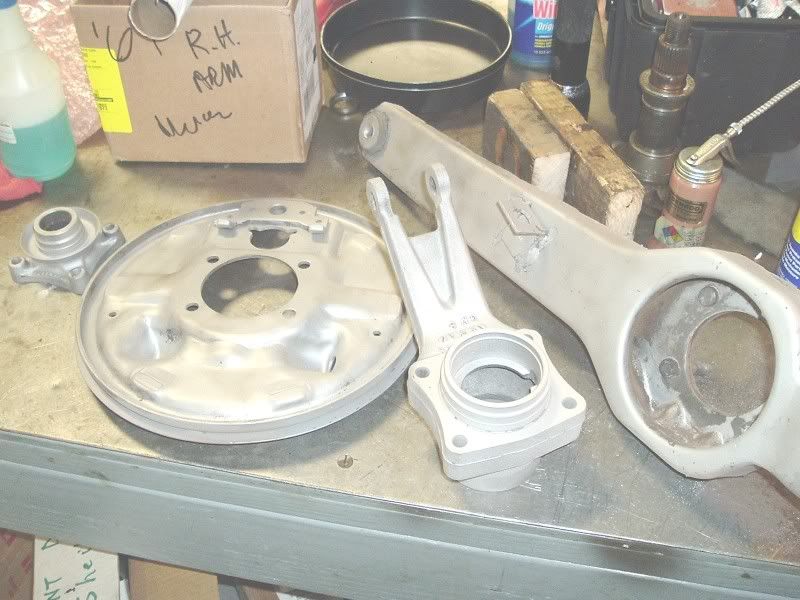
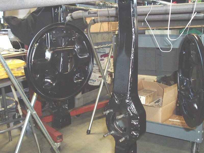
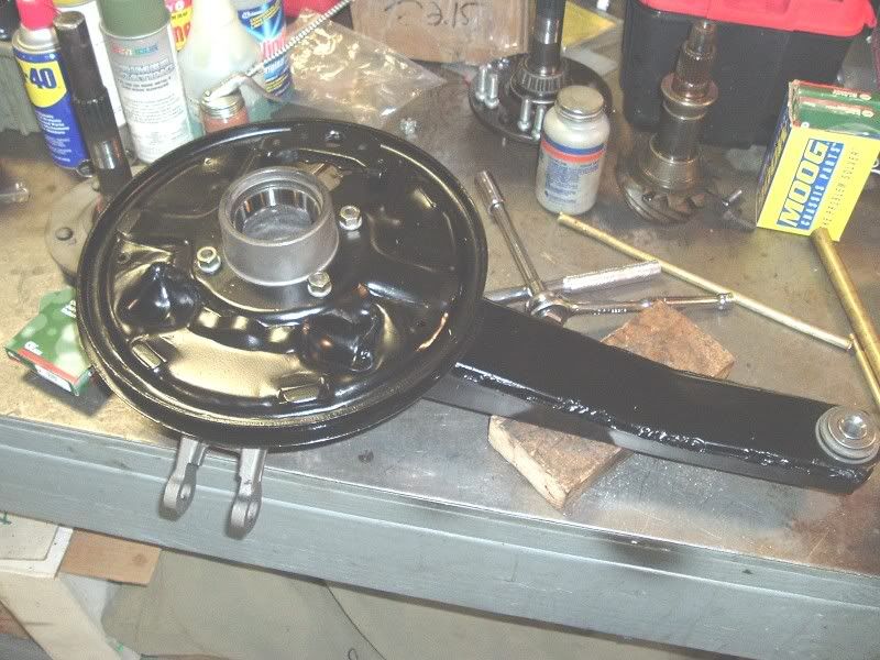
Here is the LH arm as I got it in. They are not in bad shape for 42 years old and probably because this is a CA car.
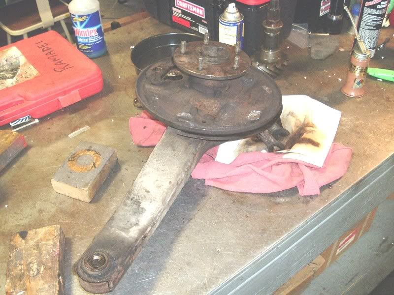
The front bushings are dry rotted but that not unusual.New rubber bushings will be used to restore that new car feel.
Here I've broken down the arm. The bearings were the original Hyatt bearings. The seals were shot and the LH spindle thread were rolled.
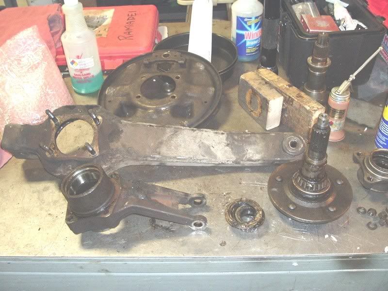
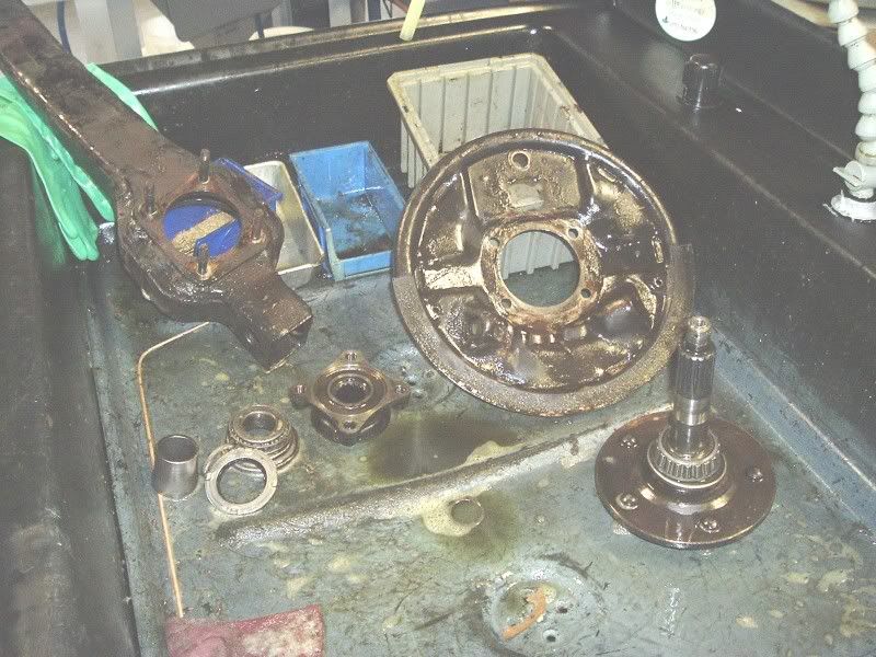
Parts were washed of 40 years of dirt and old grease. This was original "brown" grease for you numbers guys.
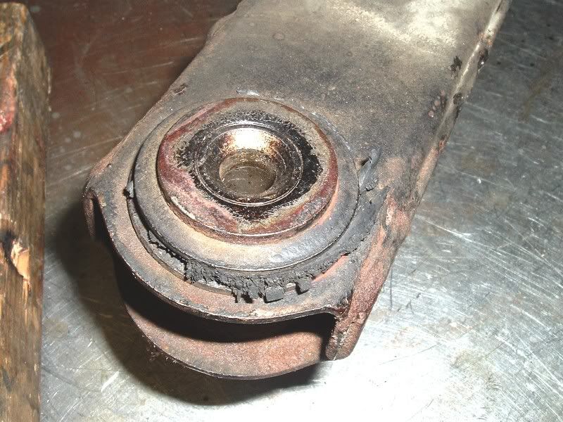
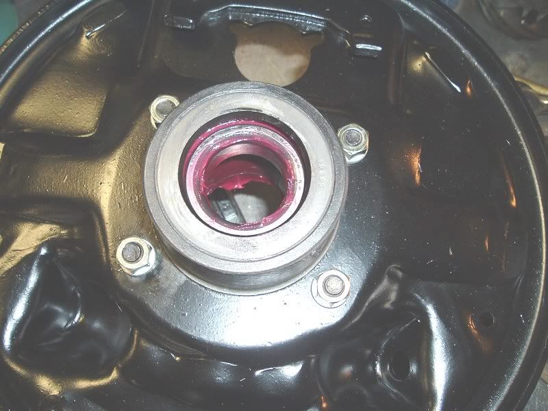
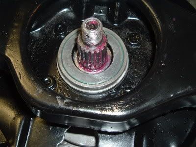
Here is a shot of those rolled threads on the spindle.

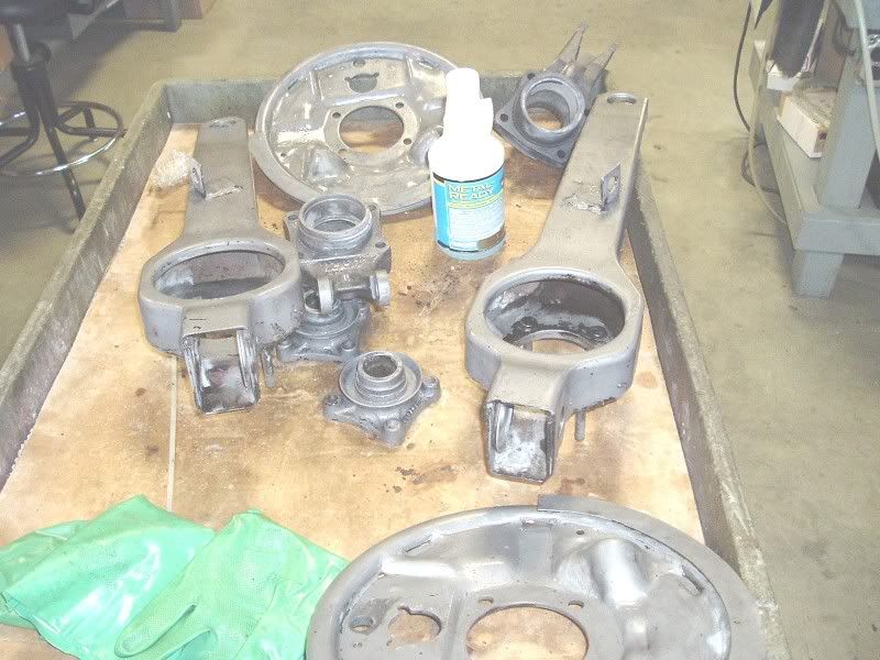
Here are the parts after I blasted them. Ready for POR15 prep and painting.
[That's about it for now.
Enjoy and I hope it helps you do the job if you decide to do so. You can also follow up on the later arm post I have going on over in C3. http://forums.corvetteforum.com/show....php?t=1229686
Here is the LH arm as I got it in. They are not in bad shape for 42 years old and probably because this is a CA car.
The front bushings are dry rotted but that not unusual.New rubber bushings will be used to restore that new car feel.
Here I've broken down the arm. The bearings were the original Hyatt bearings. The seals were shot and the LH spindle thread were rolled.
Parts were washed of 40 years of dirt and old grease. This was original "brown" grease for you numbers guys.
Here is a shot of those rolled threads on the spindle.
Here are the parts after I blasted them. Ready for POR15 prep and painting.
[That's about it for now.
Last edited by gtr1999; 06-05-2006 at 12:40 PM.
 04-08-2006, 07:51 PM
#2
Le Mans Master

All looks pretty good - aside from the mucked up threads.
The only real difference that I can see from a C3 TA is the backing plate.
Anything else that makes 63-64 unique ?

The only real difference that I can see from a C3 TA is the backing plate.
Anything else that makes 63-64 unique ?
04-09-2006, 09:08 AM
#3
Tech Contributor
Thread Starter
Dave the bearing support is a little different and interestingly they have the grease wells in them. This makes a another change in the years as the mid C2's didn't have a well then the early C3 had them? Maybe there were a couple of different suppliers of these? Of course the spindle lugs are different length and there is no PB cable bracket welded on.
04-09-2006, 03:43 PM
#4
Tech Contributor
Thread Starter
Here I'm removing the front bushings. I could have done this with an oversize drill but I have the Bridgeport sitting here.
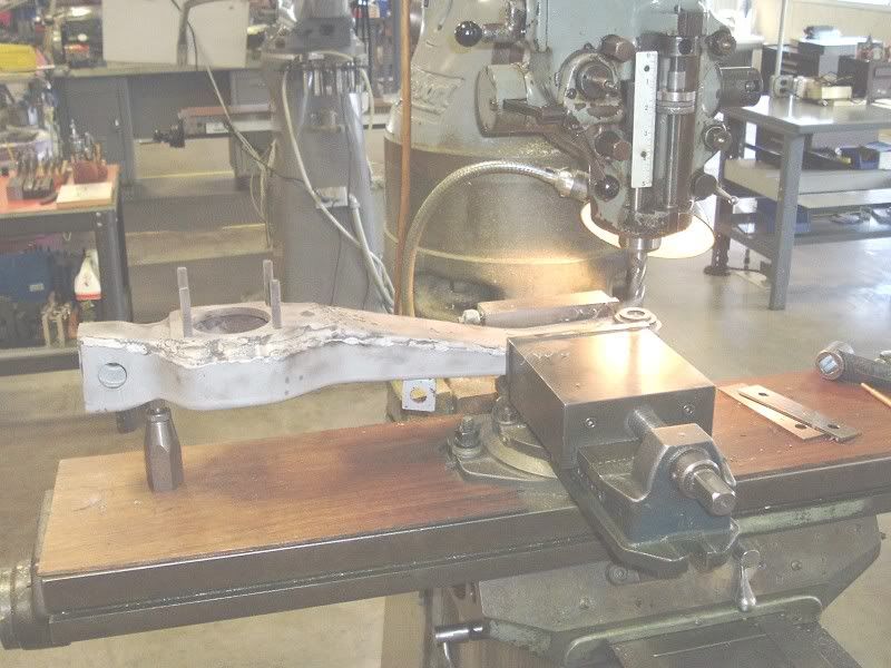
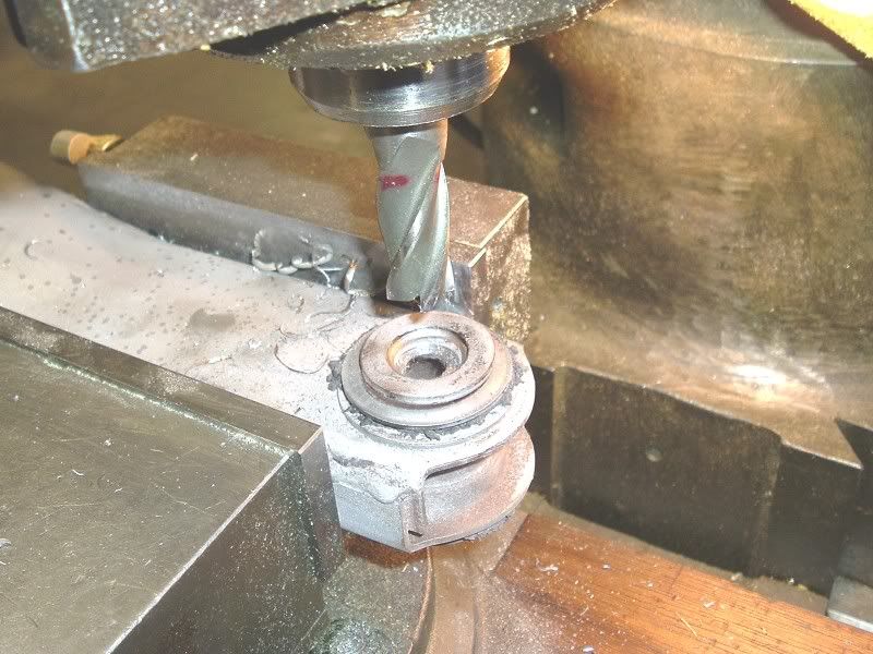
After getting the bushings out and cleaning the parts again I POR15 Metal Readied them for 30 minutes then washed them again.
After getting the bushings out and cleaning the parts again I POR15 Metal Readied them for 30 minutes then washed them again.
Last edited by gtr1999; 06-05-2006 at 12:41 PM.
04-10-2006, 06:32 PM
#5
Tech Contributor
Thread Starter
Here some more pictures from last night.
After POR15 metal ready prep I painted them with POr15 black, then when just about dry and light tack,I shot the top coat of satin black.
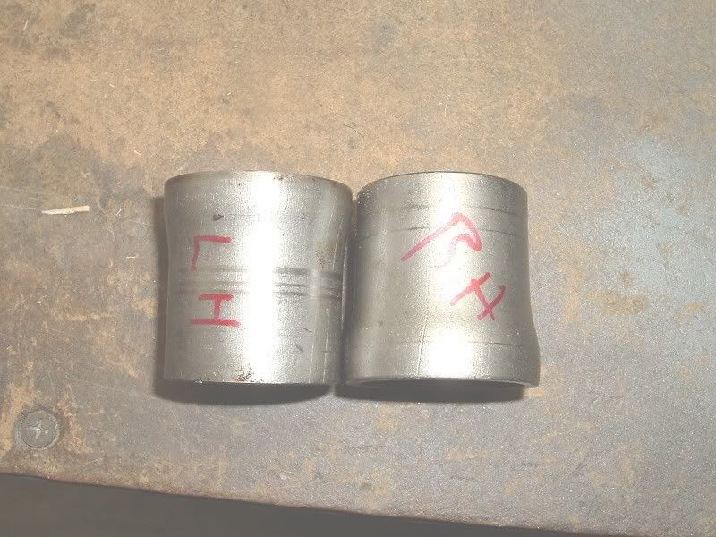
With the parts drying for a couple of days to harden I worked on the the bearing spacers. You hardly ever have to replace these but they should be parallel ground. I know a few places don't take the time to do this but it makes a difference. I don't trust the finish of either used or new replacement spacers- always grind them.
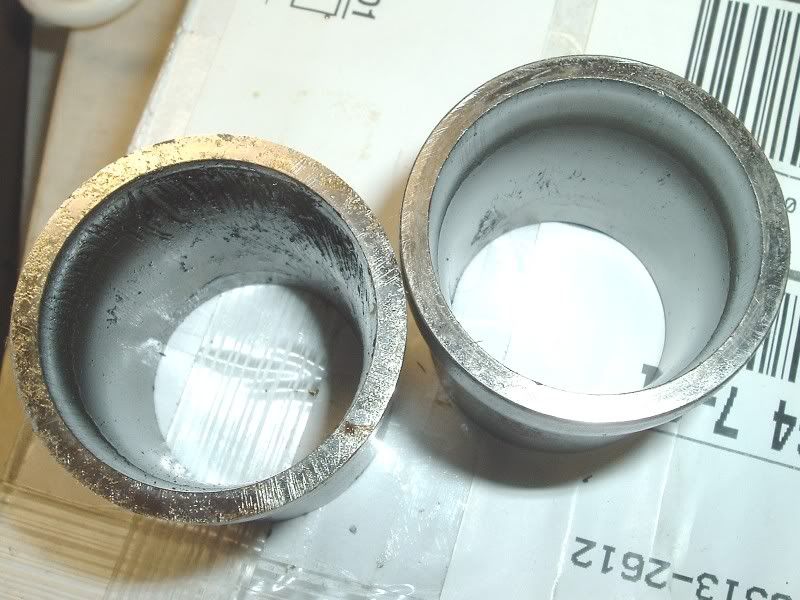
Here are the faces as they came out of the car. You can see the surfaces are not flat.
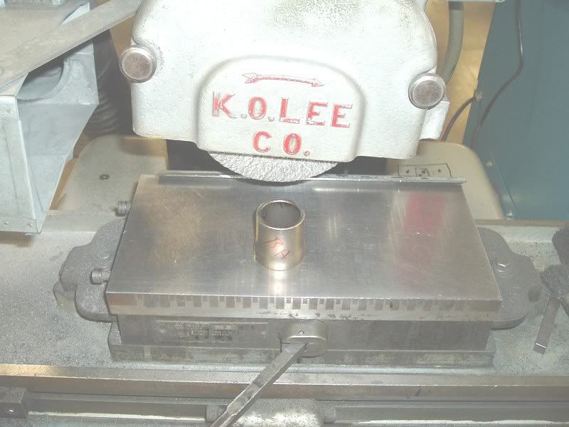
Here I'm grinding them on a KO Lee surface grinder
Here the left is ground and the right is "as it came out"
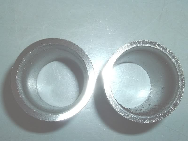
Don't skip this step if you want the best job.
After POR15 metal ready prep I painted them with POr15 black, then when just about dry and light tack,I shot the top coat of satin black.
With the parts drying for a couple of days to harden I worked on the the bearing spacers. You hardly ever have to replace these but they should be parallel ground. I know a few places don't take the time to do this but it makes a difference. I don't trust the finish of either used or new replacement spacers- always grind them.
Here are the faces as they came out of the car. You can see the surfaces are not flat.
Here I'm grinding them on a KO Lee surface grinder
Here the left is ground and the right is "as it came out"
Don't skip this step if you want the best job.
Last edited by gtr1999; 06-05-2006 at 12:47 PM.
04-15-2006, 06:21 PM
#6
Tech Contributor
Thread Starter
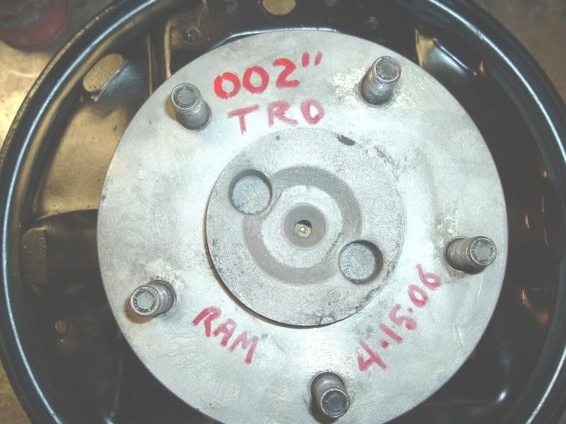
I've been pretty busy so this is the first update I had in a week. I finished up the RH arm today and set the end paly to between .0015-.002" so I'll call it .002" These arms are the ture CA dry climate ones and I'm sure the rest of the car is the same way. It was a pleasure to work on something in nice shape that finished well.
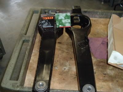
Here are both arms with fresh paint and POR15 and new bushings installed.
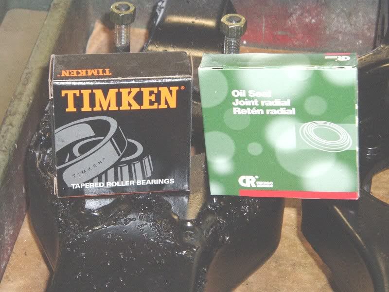
Here are the parts I use Timken and CR seals. Some kits have CR seals but most use cheaper seals. I'd rather pay more for the better seals, but that's one of your choices when you do this job. be sure if you buy them they come in the original boxes and are wrapped- I've found some vendors don;t always do this.
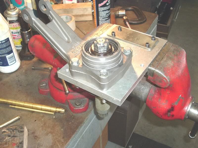
Here I have the support in my setup fixture and have the setup tool in place. I already ground the shim to fit at .0015-.002" endplay @ 100 ft/lbs. I use a new nut and washer on final assembly too.
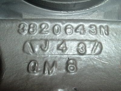
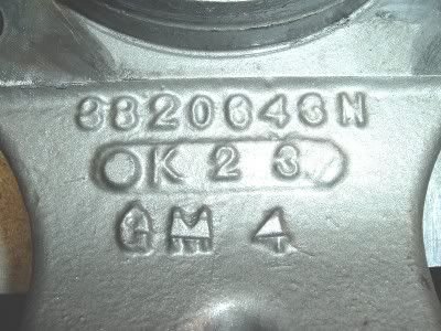
Here is the date code on the RH support. J 4 3- Oct 4th 1963!
Here are the new bushings in the RH arm

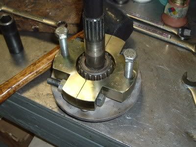
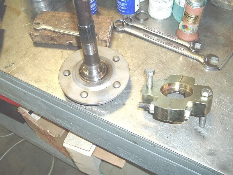
The RH spindle was still good, so I cleaned it up, chased the threads on the spindle and studs and removed the old bearing. Here's the tool
RH arm, new races installed, ready for assembly.
Here are both arms with fresh paint and POR15 and new bushings installed.
Here are the parts I use Timken and CR seals. Some kits have CR seals but most use cheaper seals. I'd rather pay more for the better seals, but that's one of your choices when you do this job. be sure if you buy them they come in the original boxes and are wrapped- I've found some vendors don;t always do this.
Here I have the support in my setup fixture and have the setup tool in place. I already ground the shim to fit at .0015-.002" endplay @ 100 ft/lbs. I use a new nut and washer on final assembly too.
Here is the date code on the RH support. J 4 3- Oct 4th 1963!
Here are the new bushings in the RH arm
The RH spindle was still good, so I cleaned it up, chased the threads on the spindle and studs and removed the old bearing. Here's the tool
RH arm, new races installed, ready for assembly.
Last edited by gtr1999; 06-05-2006 at 12:54 PM.
04-15-2006, 06:34 PM
#7
Tech Contributor
Thread Starter
I was running out of room so I had to start another post.
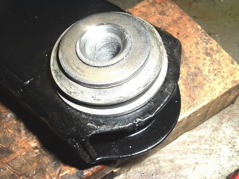
Here the outer brg is greased, and seal installed.
Here the spindle is already pressed on the outer bearing and inner bearing. Now will install the shield, yoke,new washer and nut.
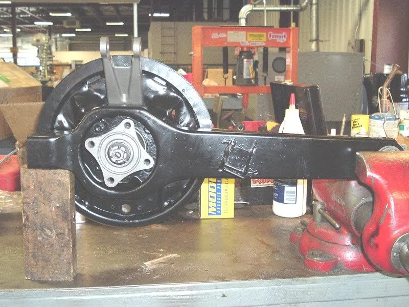
The final product. Clean,painted, .002 endplay, threaded holes all chased, ready for brake shoes.
Here the outer brg is greased, and seal installed.
Here the spindle is already pressed on the outer bearing and inner bearing. Now will install the shield, yoke,new washer and nut.
The final product. Clean,painted, .002 endplay, threaded holes all chased, ready for brake shoes.
Last edited by gtr1999; 06-05-2006 at 12:56 PM.
The following users liked this post:
jeffrey864 (04-14-2024)
04-15-2006, 06:40 PM
#8
Safety Car


Member Since: Nov 2000
Location: Clinton Township MI
Posts: 4,750
Received 118 Likes
on
97 Posts
Cruise-In III Veteran

Gary,
Very thorough step by step walk through. Appreciate all the pics as you did this. This is just you displaying your consistency when you rebuild somethin'. For you forum folks Gary did my steering box rebuild...excellent work consistent with these torque arm rebuild pics.
Have yet to get my '5 on the road to test this first hand (in the middle of Classic Auto Air install).
Hey all, let me be the first to wish you all a HAPPY EASTER!
Regards,
Jim
04-15-2006, 07:07 PM
#9
Tech Contributor
Thread Starter
Thanks Jim, Happy Easter to you too.
Keep me posted on your project. I still have to finish the CCA install too and really don't want to.
Keep me posted on your project. I still have to finish the CCA install too and really don't want to.
04-15-2006, 07:42 PM
#10
Melting Slicks


I did my t-arms last year and I feel better about what I did as I see your progression. Though I did not parallel grind my bearing sleeves. I do like that idea.
I did have one question though. I see from your pictures that the finished bushing install has left the center sleeve protruding a bit past the washer. I tried a couple of times to get it flared just right so as to not have the sleeve stick out, and did OK except for one side. (cost me a couple of sleeves too).
On that side, I just filed the portion of sleeve that stuck out (about
.020") flush with the washer. I did this so the alignment shims lay flat aganst the sleeve and the washer.
Are you concerned with the alignment shims only being supported by the center sleeve that protrudes or did I just waste my time?
04-15-2006, 08:15 PM
#11
Tech Contributor
Thread Starter
The flare can be ground flat if needed, I usually do that but just touched them with a file. I'll probably touch them both when I finish the LH arm.
Last edited by gtr1999; 04-16-2006 at 01:00 PM.
04-16-2006, 01:00 PM
#12
Tech Contributor
Thread Starter
Here is the LH date code K 2 3 (Sept 2 1963)
Last edited by gtr1999; 06-05-2006 at 12:57 PM.
04-16-2006, 04:05 PM
#13
Safety Car
Originally Posted by NHvette
All looks pretty good - aside from the mucked up threads.
The only real difference that I can see from a C3 TA is the backing plate.
Anything else that makes 63-64 unique ?
The only real difference that I can see from a C3 TA is the backing plate.
Anything else that makes 63-64 unique ?
The '63-'64 trailing arms don't have the inboard welded on 'wing' that the later year T-arms have. The rubber bumper assembly is mounted outboard of the frame rails on '63-'64 cars compared to directly underneath the frame rail on later year cars.
The trailing arms on my '64 were recently rebuilt, too. Having the complete rear end assembly removed from the car also allowed assess for a long overdue fiberglas repair job on the right rear lower tub. BUBBA had blown the right side inboard U-joint which left a pretty good sized gash in the tub fiberglas.
I figured to tackle the trailing arm/bearing/spindle rebuild job myself on a 'learn as you go' basis'. Using the CSM as a guide and some other references the job went well! .. The trailing arms looked much like what grt1999 showed in his rebuild pictorial - still in pretty fair shape after 40 years. The old trailing arm bushings were drilled out using one of those 'step' drill bits. BTW, grt1999 - NICE shop and equipment! ..
 ..
.. The left side spindle had threads that were pretty much toast. The right side spindle threads appeared to be 'ok', but .? .. I opted for brand new spindles for peace of mind. The driveshaft and halfshafts went out for rebalancing. I was surprised how much weight needed to be added to bring the halfshafts into balance. One halfshaft needed weight on both ends; the other halfshaft, only one end.
I also used Timken bearings and Mobil 1 grease in the spindles. With the bearing set up tool I wanted, and ended up with, .001 end play on both sides. After the new bearings were transferred onto the new spindles and everything tightened to spec I ended up with .002 clearance on one side and .003 on the other. Maybe the set up end play on the spindle tool should have been set at .000? ..
New crossarm sombrero bushings, new strut arm bushings, new shocks as well as the trialing arm bushings - all the stuff with rubber in it got replaced.
The underside of the body, rear end components, frame, etc., everything was cleaned and repainted. Looks real nice now!
04-16-2006, 07:52 PM
#14
Tech Contributor
Thread Starter
Mrg sounds like you have a nice 64 there. I just emailed you a question on it.
Thanks
Gary
Thanks
Gary
04-16-2006, 08:04 PM
#15
Bud2
Member Since: Jul 2005
Location: Warrnambool Victoria
Posts: 1,237
Likes: 0
Received 4 Likes
on
4 Posts

I wish I had someone local to undertake quality work, I wish I had someone to help me do quality work like that, I wish I had easy access to parts, I wish I had your workshop....... Oh well, I still love my wife AND my 64!
04-17-2006, 10:24 AM
#16
Tech Contributor
Thread Starter
Originally Posted by Bud2
I wish I had someone local to undertake quality work, I wish I had someone to help me do quality work like that, I wish I had easy access to parts, I wish I had your workshop....... Oh well, I still love my wife AND my 64!
04-17-2006, 11:21 AM
#17
Safety Car
Originally Posted by gtr1999
Mrg sounds like you have a nice 64 there. I just emailed you a question on it.
Thanks
Gary
Thanks
Gary
The email hasn't shown up. I guess the email didn't go through? ..
04-17-2006, 12:38 PM
#18
Burning Brakes


Gary; great job! couple of ques. what is your reason for setting the end play so tight? What is your opinion on slip fitting the spindle bearings? ever see a no web early 63 spindle support? last ques,
how about a tutorial on tapered roller bearings and why they must have end play? that detail on the spacer is very infomative, I will incorporate that on my next rebuild.
Thank You,
rene
how about a tutorial on tapered roller bearings and why they must have end play? that detail on the spacer is very infomative, I will incorporate that on my next rebuild.
Thank You,
rene
04-17-2006, 07:14 PM
#19
Tech Contributor
Thread Starter
I set all spindle bearings to .0015-.002" It plays much more of a difference on the 65-82 disc brake cars where loose endplay and rotor runout affect brake piston action and caue air in the system.
The best bearing information is on the Timken site they have excellant reference material.
I never paid that much attention to the supports, most of them have been changed to what every was available at the time. I might even have a webless support here, nut sure?
I've found a big difference in setting up these bearings and the endplay by parallel grinding the shim and spacers. I've found about a .003" difference in using the spacer "as is" vs ground. I grind even new shims and only replace the spacers if someone wrecked them prior to me servicing them. I don't try and go through a shim kit but rather grind one to fit.
04-18-2006, 12:55 AM
#20
Burning Brakes
Hey gtr1999 that is some quality work you do. I'm in the process of doing a ground off resto on my 65 coupe. I see by your above post you have helped persons from coast to coast and lo and behold even Canada. Although I wish I had access to all those tools and machines you have but I don't. Since I won't be getting my Trailing arms done for a little while but when I do I wouldn't mind if you could fill me in on the details of approximate cost of doing business. I like the quality work you do. For me if I do it myself or farm it out I always look for quality guys that do quality work. I've saved this thread because the pics are awesome. Thanks.
65-StingRay
65-StingRay