Help with PCV system
 03-18-2008, 03:57 PM
#1
Instructor

Thread Starter
This picture show the extent of my PCV system. This is an old race car and relied on breater hoses from both rocker arm covers and a hose from the block to an expansion tank. This new to me block does not have the piece from the block adapting to the hose. I have know idea what it should look like other than a press fit with a 1/4 inch screw. What should I do for this setup?
 03-18-2008, 04:49 PM
#2
Melting Slicks


The picture didn't come through. Or, my firewall blocked it.
If you have breather holes in both rocker arm covers, you don't need one from the back of the block. The 2 rocker arm cover holes are waht Chevy used in late 60s, 70s, and into the 80s. Look at how Chevy plumbed the PCV system for these cars.
If you have breather holes in both rocker arm covers, you don't need one from the back of the block. The 2 rocker arm cover holes are waht Chevy used in late 60s, 70s, and into the 80s. Look at how Chevy plumbed the PCV system for these cars.
03-18-2008, 04:58 PM
#3
Safety Car


It would help it you filled out your PROFILE or at least state what year/engine/hp/etc you are wanting information for.
George.
George.
03-18-2008, 05:20 PM
#4
Team Owner


Member Since: Mar 2003
Location: Greenville, Indiana
Posts: 26,118
Received 1,843 Likes
on
1,398 Posts

With this block, you have the luxury of making any configuration used from '55 to the end of the production run on 1st generation sb's. What is it you're trying to do? Race car? Driver? Judging?
03-18-2008, 06:02 PM
#5
Instructor
Thread Starter
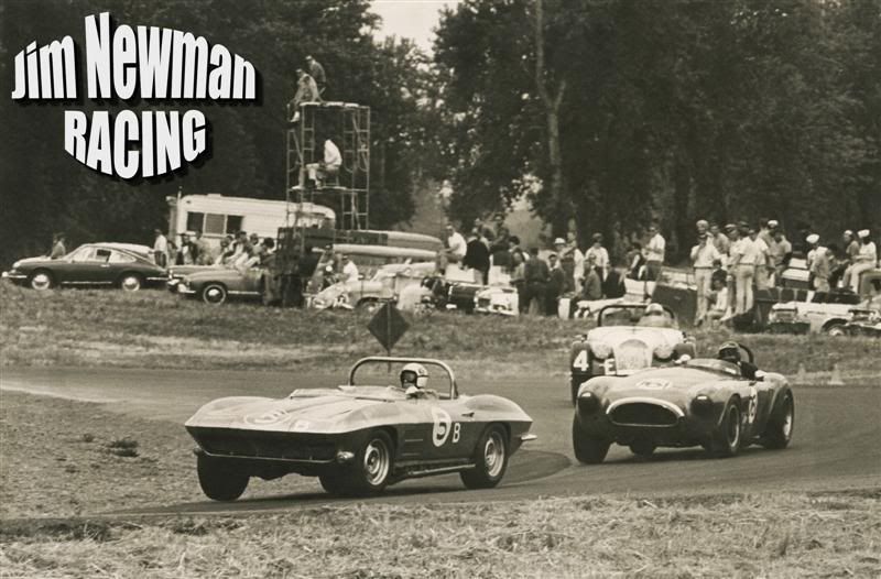
Driver during the week and a road race track day car a couple times each year. The theme of the car is keeping with it's racing background.
03-18-2008, 06:25 PM
#6
Burning Brakes


Member Since: May 2005
Location: Fairfield County CT
Posts: 1,012
Likes: 0
Received 6 Likes
on
4 Posts
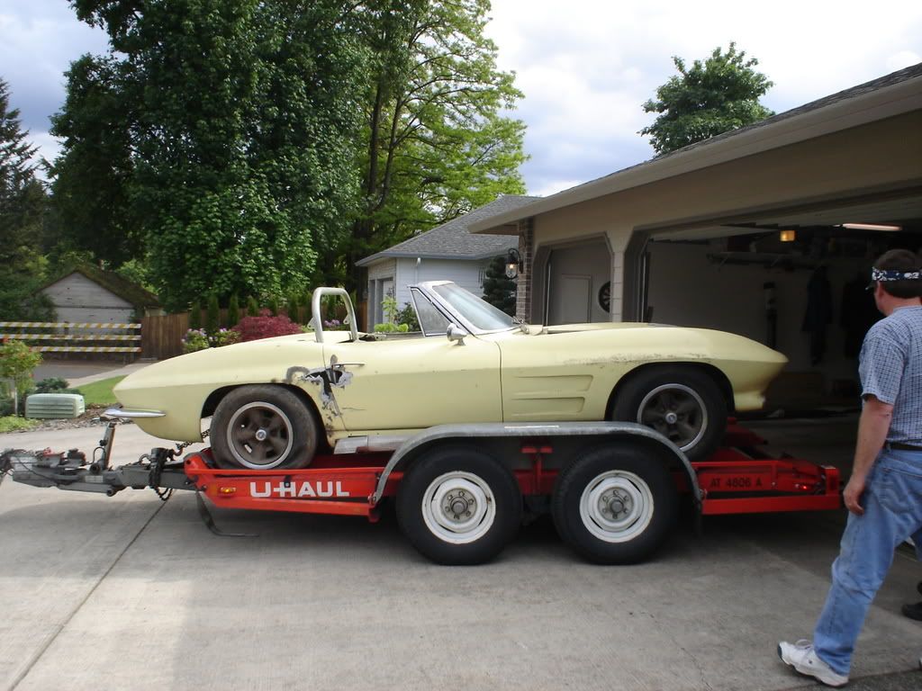
In addition to filling out your profile, we'd be curious to see some pics of your car, in racing trim as well as its current configuration.
Good luck with your PCV issue!
Good luck with your PCV issue!
03-18-2008, 06:46 PM
#7
Tech Contributor
Roger,
I think the question you may be asking is: What parts am I missing for a basically stock looking configuration.
My 65 327/350 has the following:
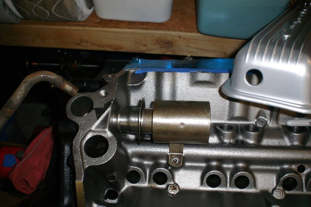
1) Metal tube that bolts to the top of the block, in that big hole you see next to the distributor hold. That metal tube isn't very long, and has a large diameter rubber hose that connects the tube, to a large fitting on the bottom of the air cleaner
2) An oil fill tube with a metal fitting on the side
3) A metered orifice fitting in the side of my Holley 2810 carb
4) A rubber hose joining the metal fitting in the oil fill tube, to the metered orifice in the side of the carb.
This photo shows all 4 pieces, but for the air cleaner.

I think the question you may be asking is: What parts am I missing for a basically stock looking configuration.
My 65 327/350 has the following:
1) Metal tube that bolts to the top of the block, in that big hole you see next to the distributor hold. That metal tube isn't very long, and has a large diameter rubber hose that connects the tube, to a large fitting on the bottom of the air cleaner
2) An oil fill tube with a metal fitting on the side
3) A metered orifice fitting in the side of my Holley 2810 carb
4) A rubber hose joining the metal fitting in the oil fill tube, to the metered orifice in the side of the carb.
This photo shows all 4 pieces, but for the air cleaner.
03-18-2008, 07:06 PM
#8
Team Owner
Member Since: Mar 2003
Location: Greenville, Indiana
Posts: 26,118
Received 1,843 Likes
on
1,398 Posts
Your description of what goes there is correct as far as it goes. It's a hat section that shoves in the block and a long 1/4" bolt holds it in place. Branching off the hat section are a variety of style of tubes. Some are a road draft tube that goes down over the bellhousing. Some have a nipple sticking out about an inch long that you can slip a pcv hose over and route it to a valve and vacuum source and some have a larger tube running to the air inlet system to siphon off filtered air to enter the crankcase.
It doesn't matter whether the flow goes in or out that hole in the block. You just have to have a vacuum source with a pcv valve or restrictor fitting plumbed in one end of your crankcase and clean filtered air on the other end or side feeding the draw of the vacuum.
I have no idea what you need for your racing needs. If you have a lot of blowby and you're pretty fast on the track, your engine will probably overload the pcv system and start blowing oil out somewhere.
I wouldn't keep what you have in any case. You'll have oil vapor everywhere and not an effective system to draw out moisture and contaminants in your crankcase .
03-18-2008, 07:09 PM
#9
Tech Contributor
Roger, can you help us out by telling us what your real goal is, and what year of car you are working on?
03-18-2008, 08:06 PM
#10
Instructor
Thread Starter
Ahhh, you make an excellent point. I had 63-67 on the brain, but yes my 62 has a road draft tube that goes down along the belhousing and dumps out next to the ground. For that matter, so does my 56 Olds.
Roger, can you help us out by telling us what your real goal is, and what year of car you are working on?
Roger, can you help us out by telling us what your real goal is, and what year of car you are working on?
All the missing parts had me confused, and the thought of oil blow by all over the place brought me to ask advice from the forum folks. My main concern is whether the system needs to have a vaccum source, or just a big catch can for the three breather sources.
03-18-2008, 08:10 PM
#11
Instructor
Thread Starter
 03-18-2008, 10:51 PM
#13
Race Director

Member Since: Jun 2006
Location: Inverness FL
Posts: 17,891
Received 727 Likes
on
621 Posts
St. Jude Donor '07
1963 convertible. I live 7 miles from Portland International raceway and am a member of several car clubs. These clubs make running track days very affordable and fun. I want this car to be fast on the track but still somewhat driveable on the street. I am sure this is completely contradictory, but if I can sacrafice some on both ends I will be happy.
All the missing parts had me confused, and the thought of oil blow by all over the place brought me to ask advice from the forum folks. My main concern is whether the system needs to have a vaccum source, or just a big catch can for the three breather sources.
All the missing parts had me confused, and the thought of oil blow by all over the place brought me to ask advice from the forum folks. My main concern is whether the system needs to have a vaccum source, or just a big catch can for the three breather sources.
Bill
03-18-2008, 11:00 PM
#14
Race Director

Member Since: Mar 2001
Location: Mustang OK
Posts: 13,852
Received 3,772 Likes
on
1,674 Posts
2023 C1 of the Year Finalist - Modified
2015 C1 of the Year Finalist

Up through 67, all small blocks had the crankcase vent hole in the rear of the block. ALLLLLLLLLLLLLLLLLLLLLL of them used the vapor seperator can under the intake as in the top picture.
From there, there were various configurations, BUT, all of them included SOME KIND of inlet (breather cap on the oil filler tube plumbing from the air cleaner) air for the crankcase and SOME KIND of outlet for the crankcase. All engines still have this setup in some form or fashon-----------------ALL of them!
Up through 62 (EXCEPT Calif), all engines had a road draft tube. I can only guess, but I presume you know what a road draft tube looks like (if not, I'll show you a picture). The road draft tube was attached to the hole in the rear of the block with a long 1/4in bolt like the one in the below picture. The bolt had a small washer and a seal, as you can see.
Beginning in 63 to 67, there were multiple configurations of positive crankcase ventilation (PCV). Except for Calif cars in 62, all engines got a PCV valve in 63-up. And this was done in several ways (the road draft tube was gone forever). Many engines used the vent hole adapter and long bolt (below) with a hose connected to the adapter and then connected to a PCV valve at the base of the carb. Some engines had various shapes of tubes connected to the vent hole which went to the base of the air cleaner and another hose connected to a fitting and/or PCV valve at the oil filler tube. As already mentioned, inlet air could either come into the oil filler tube and be sucked out of the rear vent hole or vice versa. It all depended on the configuration of the engine/carb/FI setup.
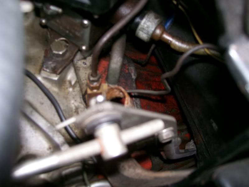
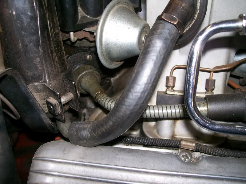
The 2nd and 3rd pictures are the PCV setup for a 63 FI car (customer's car). There was simply a rubber gormmet with a tube in it that was pressed into the rear vent hole, then it snaked under the distributor and connected to a PCV valve that screwed into the side of the FI plenum. Inlet air came from the air cleaner over to the oil filler tube. The 64-65 FI engines reversed this PCV routing. Inlet air went into the rear vent hole and was sucked out through the oil filler tube into the FI plenum.
Bottom line, fresh air into the crankcase (SOMEWHERE) and vapors (dirty air) sucked out into the carb or FI (YUK!!!!).

By the way, it's your car, your money and you have the right to do anything you please with it and NO ONE should criticize you. BUT, it sure hurts me to see holes cut into the finned alum Corvette script valve covers.
If by chance those are no-line valve covers, and they were mine, I would locate a person who is an EXCELLENT alum welder, have the holes welded, grind down the weld and finish it smooth and install the covers with the repair toward the rear.
From there, there were various configurations, BUT, all of them included SOME KIND of inlet (breather cap on the oil filler tube plumbing from the air cleaner) air for the crankcase and SOME KIND of outlet for the crankcase. All engines still have this setup in some form or fashon-----------------ALL of them!
Up through 62 (EXCEPT Calif), all engines had a road draft tube. I can only guess, but I presume you know what a road draft tube looks like (if not, I'll show you a picture). The road draft tube was attached to the hole in the rear of the block with a long 1/4in bolt like the one in the below picture. The bolt had a small washer and a seal, as you can see.
Beginning in 63 to 67, there were multiple configurations of positive crankcase ventilation (PCV). Except for Calif cars in 62, all engines got a PCV valve in 63-up. And this was done in several ways (the road draft tube was gone forever). Many engines used the vent hole adapter and long bolt (below) with a hose connected to the adapter and then connected to a PCV valve at the base of the carb. Some engines had various shapes of tubes connected to the vent hole which went to the base of the air cleaner and another hose connected to a fitting and/or PCV valve at the oil filler tube. As already mentioned, inlet air could either come into the oil filler tube and be sucked out of the rear vent hole or vice versa. It all depended on the configuration of the engine/carb/FI setup.
The 2nd and 3rd pictures are the PCV setup for a 63 FI car (customer's car). There was simply a rubber gormmet with a tube in it that was pressed into the rear vent hole, then it snaked under the distributor and connected to a PCV valve that screwed into the side of the FI plenum. Inlet air came from the air cleaner over to the oil filler tube. The 64-65 FI engines reversed this PCV routing. Inlet air went into the rear vent hole and was sucked out through the oil filler tube into the FI plenum.
Bottom line, fresh air into the crankcase (SOMEWHERE) and vapors (dirty air) sucked out into the carb or FI (YUK!!!!).
By the way, it's your car, your money and you have the right to do anything you please with it and NO ONE should criticize you. BUT, it sure hurts me to see holes cut into the finned alum Corvette script valve covers.
If by chance those are no-line valve covers, and they were mine, I would locate a person who is an EXCELLENT alum welder, have the holes welded, grind down the weld and finish it smooth and install the covers with the repair toward the rear.
Last edited by DZAUTO; 03-18-2008 at 11:07 PM.
03-19-2008, 08:11 AM
#15
Instructor
Thread Starter
DZAuto, thanks for the pictures, infor , and insights on this matter. This info is exactly what I need to understand my situation and make a determination on how to proceed.
As for the valve covers, the rules for the time required extra breathing and for it to be captured. The hole saw was the answer. I hope to repair them in the future but for now I will make them work. Out of the things that could have been done to this car for the racing stuff, this is probably the only butcher job I can think of.
As for the valve covers, the rules for the time required extra breathing and for it to be captured. The hole saw was the answer. I hope to repair them in the future but for now I will make them work. Out of the things that could have been done to this car for the racing stuff, this is probably the only butcher job I can think of.