
anyone experienced with car-o-liner?
 10-09-2011, 11:09 PM
#1
Melting Slicks

Thread Starter

A few months ago I had my car measured with a car-o-liner because of a previous incident on track (thanks to abs brakes!) and there is one measurement out of spec. The tech didn't do a good job of explaining anything to me and I am not quite sure which direction I should take to get things back to spec. Basically the car had a rf impact on a soft barrier. Everything appeared arrow straight to the eye as far as frame/suspension. I measured some points using plumb bobs and checked out ok. After the car-o-liner I re-measured even more points and cannot find anything to add up to what the report says. The wheels have more toe out than prior to the incident. I am assuming rf lower arm may be bent or the crossmember may be bent or slightly rotated, but measurements and visual show no obvious signs of damage there. Any help would be appreciated.
thanks,
-V
thanks,
-V
 10-10-2011, 07:36 AM
#3
Race Director


how much is the TOE off....? If you can't see any visual damage, I'd reset the TOE and forget about it!
However, as above, let us know specifically what measurement is off and maybe we can come up with a better answer for you.
However, as above, let us know specifically what measurement is off and maybe we can come up with a better answer for you.
10-10-2011, 08:47 AM
#4
Drifting


If you have someone with a tire alignment machine that will just check your current alignment measurements you can look at the numbers to see if anything has changed.
The frame tech should have recorded the measurements and it would be worth your time going back and get the data.
The frame tech should have recorded the measurements and it would be worth your time going back and get the data.
10-10-2011, 05:53 PM
#5
Melting Slicks
Thread Starter
I don't remember what the toe is, but it is visually out quite a bit. I'd say nearly an inch total, and when I set it prior to the damage it was either 1/16" or 1/8" total out.
Looking at the report it appears as thought the measurements from the front crossmember chassis attachment bolts/points are off. From the top view I am guessing the crossmember somehow rotated clockwise or bent in that direction somehow. The way I see it that would cause the toe out condition, but I cannot seen any signs of the crossmemeber shifting.
I dropped plumbbobs from all the bolts as well as the front lower ball joints and pickup points on the lower arms then used a few chassis points as reference and everything seems to check out pretty good. Of course it is impossible to get as accurate a measurement on a garage floor with the car on jackstands, but I'd think it woud show something more to go along with the report I have.
I emailed someone at car-o-liner that said they would help me so I need to get the paperwork over there.


 10-11-2011, 12:24 AM
#11
Melting Slicks
Thread Starter
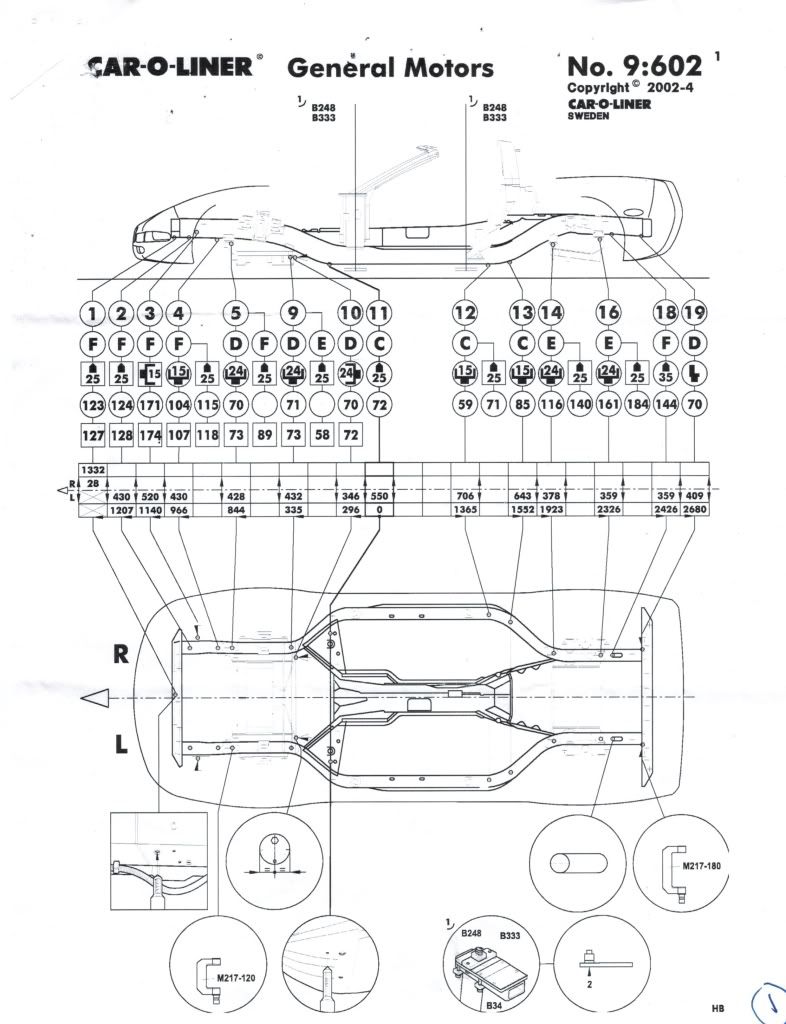
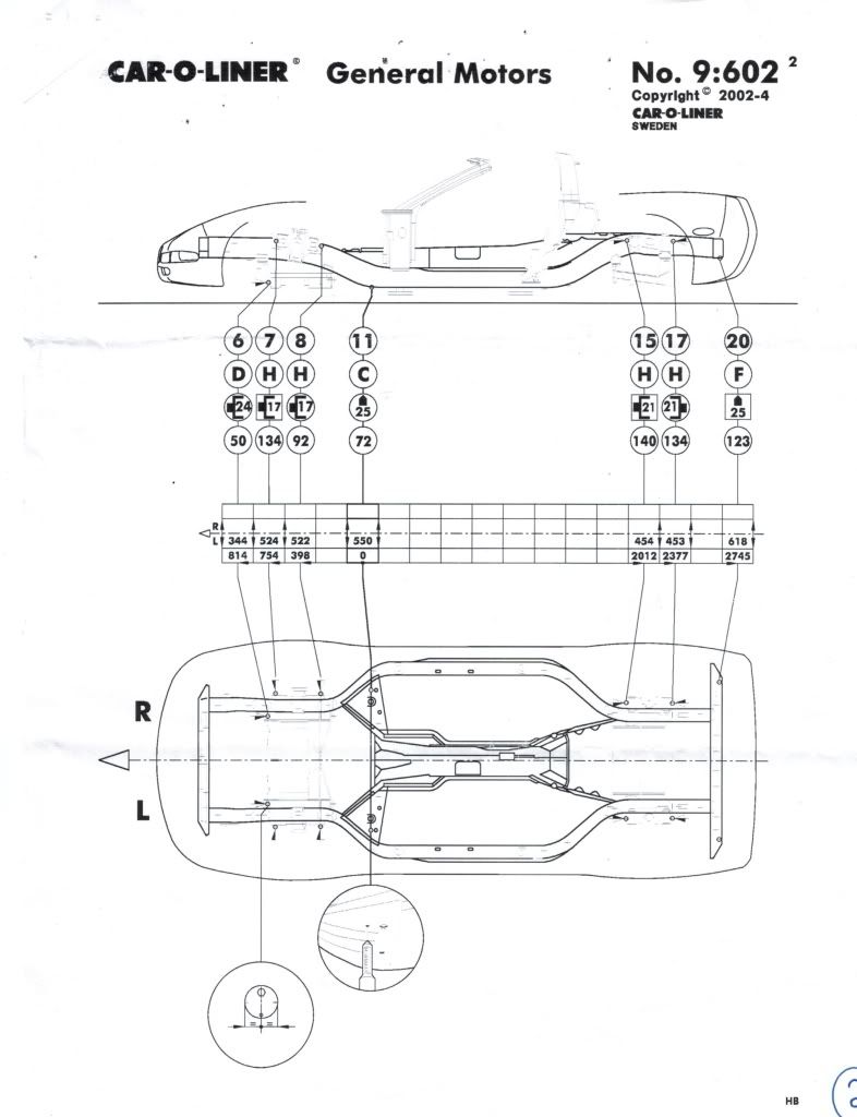
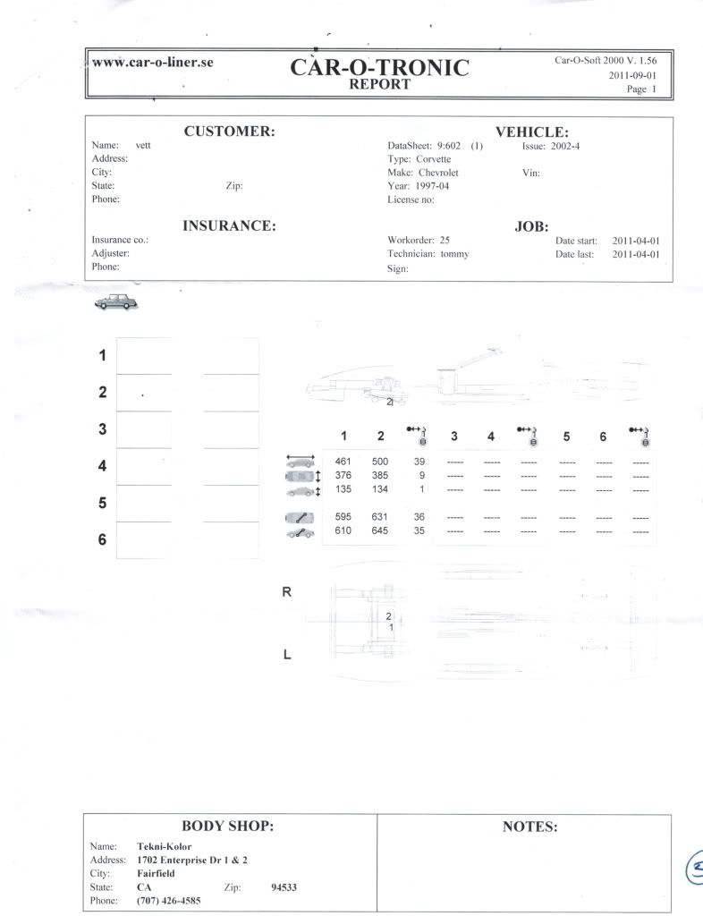
The hard copies are not much better. The diagrams are top and side view of the front crossmember and pickup points. I sent off the copies to the person at caroliner so hopefully I'll get some feedback in the next day or so.
10-11-2011, 09:08 AM
#12
Burning Brakes

THe fact that the shop wont explain it is pitiful .
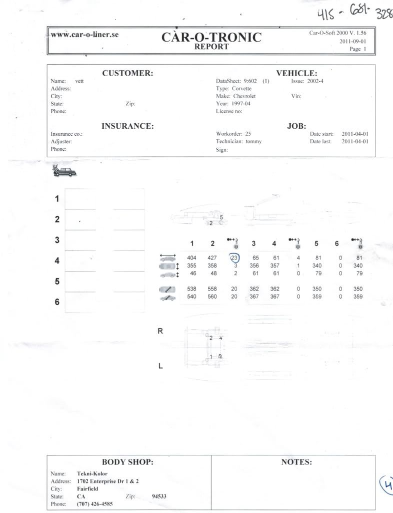
Where the #23 is circled is probably a centering point .
If only one # is out of whack tells me they just missed the correct pick up point .
Where is the @ 23 ? side of the rail ?
Where the #23 is circled is probably a centering point .
If only one # is out of whack tells me they just missed the correct pick up point .
Where is the @ 23 ? side of the rail ?
10-11-2011, 06:50 PM
#13
Melting Slicks
Thread Starter
Here is the reply I got from the car-o-liner person:
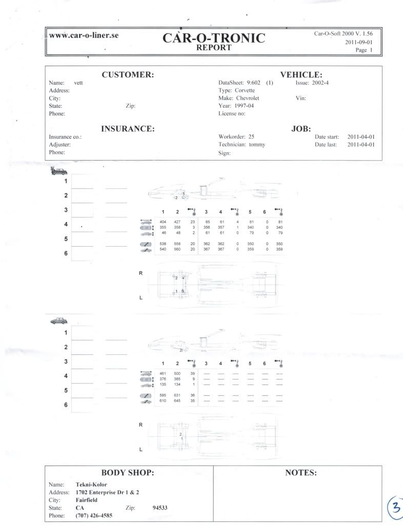
The print-outs that you sent only show comparative measuring, which means that the coordinates of one point are compared to the coordinates of a 2nd point. These reports really don’t show dimensionally how structurally correct the vehicle actually is.
It would have been much more helpful if the vehicle had been measured against the actual datasheet(9:602) that you sent.
Turns out the first two pages are the measurements of a straight chassis and they were not even used. Guess I need to have it measured elsewhere once I get some wheels so I can drive it.