
Mechanical Engineers: Torsion rate questions
 03-12-2009, 12:34 PM
#1
Tech Contributor
Thread Starter
Member Since: Jun 2004
Location: I tend to be leery of any guy who doesn't own a chainsaw or a handgun.
Posts: 18,350
Received 767 Likes
on
549 Posts

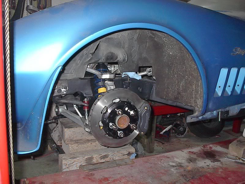
I'm trying to do some A-B comparison between steel and aluminum halfshafts. I recently put a C4 suspension under my '69, and I'm trying to mathematically compare the original 2.5" diameter steel halfshafts and the 3.5" aluminum C4 shafts I have now. I have a C3 shaft that I had cut up for setting up the new suspension, so I can measure the wall thickness of that, and I'm currently trying to find out the wall thickness of C4 shafts. Boiling it down, the main info I need is what sort of "spring" constant value do I use for aluminum? I have a formula in one of my chassis books for determining the torsion rate for tubular steel bars, but I need a value to plug in for aluminum "bars". Can anybody help me out here?
Thanks,
Mike
Thanks,
Mike


 03-12-2009, 01:18 PM
#3
Safety Car

03-12-2009, 01:24 PM
#4
Le Mans Master

Member Since: Oct 2007
Location: Akron Ohio
Posts: 8,865
Received 1,741 Likes
on
939 Posts
2023 C5 of the Year Finalist - Modified
2022 C5 of the Year Finalist - Modified
St. Jude Donor '09-'10-'11
There are different constants for different types of aluminum. I dont know if the half shafts are pure Al.
03-12-2009, 05:43 PM
#5
Race Director


you will need to completely re-figure for the change in diameter, the thickness, AND the metal properties (modulus of elasticity). If the diameter and thickness were the same, you could just compare G (modulus), but in your case you'll need to be more specific since the geometric componenet (moment of inertia) goes up with the square of the radius, but more or less linear with the thickness.
I guess REALLY simplifying, if you assume the thickness is the same, the 40% increase in diameter will cause a 100% increase in stiffness.......you can then approximate the overall stiffness proportianally to the Modulus and thickness.
btw, are you more concerned about Stiffness, or strength....they aren't necessarily at all the same!
Last edited by davidfarmer; 03-12-2009 at 10:45 PM.
03-12-2009, 08:20 PM
#6
Safety Car

The twist angle of the cross section due to a torque is
theta= TL / GJ
If you want a stiffness such that
T= K * theta
Then your stiffness is GJ / L
L=shaft length
G=shear modulus of material (alum. or steel--look up in text book or online)
J= polar moment of inertia of circular cross section. I think it's pi*radius&^4 but you should look it up.
If hollow tube--take J for the outer diameter then calc for the inner diameter and subtract the smaller value.
03-12-2009, 10:44 PM
#7
Race Director
I think he's right, is relative to radius raised to the 4th power, NOT squared. Therefore the increase in radias will quadruple your stiffness, not double it. Thickness and modulus should still be more or less linear.
Hard to keep my polar moments, area moments, and mass moments straight after 20 years.
And again, stiffness and strength are NOT the same....
Hard to keep my polar moments, area moments, and mass moments straight after 20 years.
And again, stiffness and strength are NOT the same....
03-12-2009, 11:05 PM
#8
Tech Contributor
Thread Starter
Member Since: Jun 2004
Location: I tend to be leery of any guy who doesn't own a chainsaw or a handgun.
Posts: 18,350
Received 767 Likes
on
549 Posts
you will need to completely re-figure for the change in diameter, the thickness, AND the metal properties (modulus of elasticity). I'm familiar with the conversions from one shape/size to another. My original question was essentially how to compare two shafts if one is steel and the other was aluminum. I had struck out trying to find the "constant" value for each material. If I understand things correctly, the modulus of elasticity, as you mention here, would be the item I'm looking for. If the diameter and thickness were the same, you could just compare G (modulus), but in your case you'll need to be more specific since the geometric componenet (moment of inertia) goes up with the square of the radius, but more or less linear with the thickness.
I guess REALLY simplifying, if you assume the thickness is the same, the 40% increase in diameter will cause a 100% increase in stiffness.......you can then approximate the overall stiffness proportianally to the Modulus and thickness.
btw, are you more concerned about Stiffness, or strength....they aren't necessarily at all the same!
03-12-2009, 11:23 PM
#10
Tech Contributor
Thread Starter
Member Since: Jun 2004
Location: I tend to be leery of any guy who doesn't own a chainsaw or a handgun.
Posts: 18,350
Received 767 Likes
on
549 Posts
I looked at a couple websites, and got some numbers for steel and aluminum.
Steel 29 x 10e6 psi
Aluminum 10.2 x 10e6 psi
So, once I do the math to determine the stiffness difference/ratio due to the sizes (diameter, wall thickness, and length), I'm assuming I can then just multiply that by the 10.2/29 ratio to see the final comparison ratio. Is that correct?
Thanks for all the help so far. (I'm a EE design engineer, and my mechanics courses were a few decades ago. )
)
Steel 29 x 10e6 psi
Aluminum 10.2 x 10e6 psi
So, once I do the math to determine the stiffness difference/ratio due to the sizes (diameter, wall thickness, and length), I'm assuming I can then just multiply that by the 10.2/29 ratio to see the final comparison ratio. Is that correct?
Thanks for all the help so far. (I'm a EE design engineer, and my mechanics courses were a few decades ago.
)
03-12-2009, 11:40 PM
#11
Safety Car
I looked at a couple websites, and got some numbers for steel and aluminum.
Steel 29 x 10e6 psi
Aluminum 10.2 x 10e6 psi
So, once I do the math to determine the stiffness difference/ratio due to the sizes (diameter, wall thickness, and length), I'm assuming I can then just multiply that by the 10.2/29 ratio to see the final comparison ratio. Is that correct?
Thanks for all the help so far. (I'm a EE design engineer, and my mechanics courses were a few decades ago.)
Steel 29 x 10e6 psi
Aluminum 10.2 x 10e6 psi
So, once I do the math to determine the stiffness difference/ratio due to the sizes (diameter, wall thickness, and length), I'm assuming I can then just multiply that by the 10.2/29 ratio to see the final comparison ratio. Is that correct?
Thanks for all the help so far. (I'm a EE design engineer, and my mechanics courses were a few decades ago.
)
03-13-2009, 08:33 AM
#12
Melting Slicks


Those numbers look like the ultimate tensile strength of each material, which doesn't really matter here, unless you want to compare the failure torque on each one. For torsional rigidity, you need the modulus of elasticity (E) of each (IIRC). I'm going out of town for the week tomorrow, but if I had the wall thicknesses of each and the type of Aluminum, it would honestly take about 10 minutes to create a model and test it, and get a torsional rigidity for each shaft, in ft-lb per degree of rotation. Though I'm sure you could just do hand calculations and get the same thing.
Doing a model????? This is a quick hand crank, why would you do a model for this, and really these parts are all so stiff relative to the amount of torsional windup that torsional stiffness is of no consequence. That is, there is really no practical amount of torsional deflection that will effect the drive train here. If you look at small diameter solid shaft and crank in the amount of torque in first gear, then you could see some deflection here, but with a large diameter tube, you aren't going to see any measureable twist in the shaft anyway.
Just use it and enjoy. It isn't worth the effort to calculate and compare...
03-13-2009, 09:15 AM
#13
Le Mans Master
Member Since: Feb 2000
Location: Bedford NH
Posts: 5,708
Likes: 0
Received 1 Like
on
1 Post
Cruise-In II Veteran

Those are numbers for modulus, which is what you want.
Doing a model????? This is a quick hand crank, why would you do a model for this, and really these parts are all so stiff relative to the amount of torsional windup that torsional stiffness is of no consequence. That is, there is really no practical amount of torsional deflection that will effect the drive train here. If you look at small diameter solid shaft and crank in the amount of torque in first gear, then you could see some deflection here, but with a large diameter tube, you aren't going to see any measureable twist in the shaft anyway.
Just use it and enjoy. It isn't worth the effort to calculate and compare...

But as always, what usually is the most important is not being considered here, i.e. the boundary conditions. Doing the tube section comparison is an easy hand calc, but the U joint mounts are also a significant contribution to overall stiffness and strength. What needs to be considered is the total "strain energy density", with the key word here being "density". I see this error in so many products designed by non professionals (structurally speaking). For example, to have a huge truss section on a harness bar with sheet metal end attachments and flat stock struts is like having the anchor chain for the Nimitz having one link from a dog chain. All of the strain energy will be dumped into the one small link.
03-13-2009, 08:33 PM
#14
Tech Contributor
Thread Starter
Member Since: Jun 2004
Location: I tend to be leery of any guy who doesn't own a chainsaw or a handgun.
Posts: 18,350
Received 767 Likes
on
549 Posts
I got a call from the driveshaft shop manager this afternoon. He said that they had the first shaft cut apart from the yoke, and the shortened tubing is a loose fit on the yoke. He speculated that the tubing is around .095 wall thickness, while the yokes are made for .125 wall tubing. We agreed to change direction and cut out both yokes and then install .125 wall tubing in there. It's a little more hassle and delay, but I've got plenty to keep me busy on the car in the meantime. Right now I'm working on getting the steering rack hooked up, plumbing the brake system, and a hundred other minor assemblies.

 03-14-2009, 06:09 PM
#15
Burning Brakes

Sothpaw's post will help you.
(T * r) / J <---- shear stress
theta = (T*L) / (J *G) <---- rotation bar endures
also, T= spring constant * theta <---you can find the spring constant
oh, since it's aluminum, be conservative with respect to the endurance limit.
I second what ghoffman said.
however, we can assume that for the system you have, the part your machining is the "weak link" i.e. the rest of the system exceeds the capability of the part. Else, you won't know the actual performance since something else will break and leave you with little information (will it break? or is it strong enough?)
Last edited by OKsweetrides; 03-14-2009 at 06:12 PM.
03-14-2009, 09:44 PM
#16
Safety Car
I looked at a couple websites, and got some numbers for steel and aluminum.
Steel 29 x 10e6 psi
Aluminum 10.2 x 10e6 psi
So, once I do the math to determine the stiffness difference/ratio due to the sizes (diameter, wall thickness, and length), I'm assuming I can then just multiply that by the 10.2/29 ratio to see the final comparison ratio. Is that correct?
Thanks for all the help so far. (I'm a EE design engineer, and my mechanics courses were a few decades ago.)
Steel 29 x 10e6 psi
Aluminum 10.2 x 10e6 psi
So, once I do the math to determine the stiffness difference/ratio due to the sizes (diameter, wall thickness, and length), I'm assuming I can then just multiply that by the 10.2/29 ratio to see the final comparison ratio. Is that correct?
Thanks for all the help so far. (I'm a EE design engineer, and my mechanics courses were a few decades ago.
)Post the radii and the Lengths and I'll do the comparison when I'm at work. I really will be as simple as (GJ/L)alum vs (GJ/L) steel.
If L is the same, the aluminum will be stiffer if it is just a little bigger in diameter.
Last edited by sothpaw2; 03-14-2009 at 09:47 PM.
03-21-2009, 10:11 PM
#17
Tech Contributor
Thread Starter
Member Since: Jun 2004
Location: I tend to be leery of any guy who doesn't own a chainsaw or a handgun.
Posts: 18,350
Received 767 Likes
on
549 Posts
Those are the WRONG numbers! You need the shear modulus, G. Those are the Young's (or elastic) modulii, E. Those are used for tension not torsion.
Post the radii and the Lengths and I'll do the comparison when I'm at work. I really will be as simple as (GJ/L)alum vs (GJ/L) steel.
If L is the same, the aluminum will be stiffer if it is just a little bigger in diameter.
Post the radii and the Lengths and I'll do the comparison when I'm at work. I really will be as simple as (GJ/L)alum vs (GJ/L) steel.
If L is the same, the aluminum will be stiffer if it is just a little bigger in diameter.
Instead of .125 wall tubing, they put in .138 (IIRC). I measured a few shafts I have, and here are the numbers:
3.5" Aluminum, .138" wall, and 12 1/2 inch tubing length between yokes. (My custom shafts)
3.0" steel, .098" wall, 10 1/4 inch tubing length between yokes. (C3)
2.5" steel, .098"? wall, 10 1/4 inch tubing length between yokes. (C3)
I am guessing about the early C3 shaft wall thickness, as I don't have a cut apart unit. I made my best estimate of the actual tubing length by measuring from the centerlines of the yoke welds.
Again, I appreciate whatever results and data you can supply.
03-22-2009, 08:24 PM
#18
Safety Car
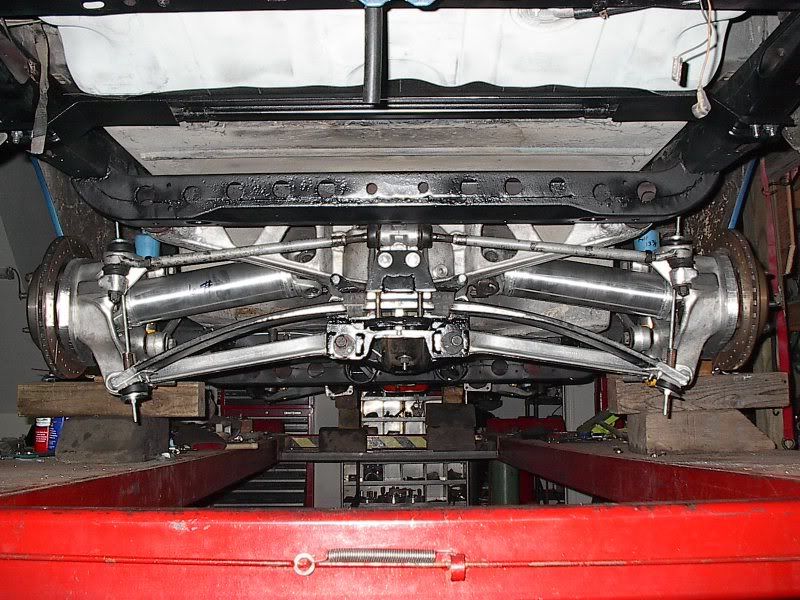
I appreciate the help. I got the narrowed/new halfshafts back from the driveline shop the other day, and put them in this weekend.
Instead of .125 wall tubing, they put in .138 (IIRC). I measured a few shafts I have, and here are the numbers:
3.5" Aluminum, .138" wall, and 12 1/2 inch tubing length between yokes. (My custom shafts)
3.0" steel, .098" wall, 10 1/4 inch tubing length between yokes. (C3)
2.5" steel, .098"? wall, 10 1/4 inch tubing length between yokes. (C3)
I am guessing about the early C3 shaft wall thickness, as I don't have a cut apart unit. I made my best estimate of the actual tubing length by measuring from the centerlines of the yoke welds.
Again, I appreciate whatever results and data you can supply.