When you click on links to various merchants on this site and make a purchase, this can result in this site earning a commission. Affiliate programs and affiliations include, but are not limited to, the eBay Partner Network.
Fix the front lift system leak problem with this final solution
Hi All,
I finally received all the mail-order parts for the "Matt Gizmo" that MAD Matt designed for fixing the front lift system's fluid leaking problem, and over this weekend I built it according to the description by Matt in this old thread. Along the way of building and testing it, I modified Matt's design slightly, and I also learned some lessons from the mistakes I made, but I finally got it working perfectly, so let me share with you all my experience of building and testing it, hopefully helping some of you doing the same....
I figured that it's probably easier for many new members to read this in a new thread, instead of going through that very long old thread, so here let me start with a new thread for nothing else other than simply the detailed steps of building and installing this gizmo, making it easy for everyone to follow along if anyone is also interested in doing the same. All credit goes to MAD Matt for his ideas behind this gizmo design and the original testing he has done. Thank you Matt!
So here we go...
1. First, all the parts ordered per Matt's recommendation:
(1) An 1" wide on two side, 1' long aluminum angle bar, to be used as the supporting structure for anchoring the overflow container in our fix solution (top center in the photo below) - order link, $5.78;
(2) A sport bike reservoir, to be used as an overflow container in our fix solution (left side in the photo) - order link, $13.99;
(3) A power brake bleeder cap, to be used as the cap on top of the C8 lift system fluid reservoir in our fix solution, replacing the cap that comes with the C8. This part come with a the cap, connected with a hose, and 2 soft rubber gaskets (center in the photo) - order link, $27.80;
(4) A 1/8" NPT to 3/16" Barb 90 degree adapter, to be used to connect a hose between the overflow container and the main left fluid reservoir in our fix solution (right-center in the photo below) - order link, $6.84;
(5) A spool of 3/16 ID-5/16 OD vinyl soft tube or hose, to be used to connect the overflow container and the main left fluid reservoir in our fix solution (right side in the photo below). Matt initially posted this as one of the required parts, which I bought, and later Matt said this is not necessary, as the brake bleed cap you buy comes with an extra hose with exactly the same size. However, I found out that the hose that come with the bleed cap is a bit hard to use, and the extra spool I bought, actually saved the day (more on that later) - order link, $5.48;
(6) A 1"-wide fiber carbon bar, as Matt's design used that to mount the overflow container apparatus to the car, so I also bought one (lower-center in the photo). However, I changed Matt's design, and skipped using this part, so for any one who followed my modified design below, you can skip purchasing this one, which saves you an extra $28 in the overall cost - order link, $28.44 with shipping.
(7) A 6-mm screw, preferably with a tension washer (or lock washer), to be used to screw the gizmo onto the car. In addition, a small screw and a nut, to mount the overflow container to the aluminum angle bar. (these are not in the photo). I got these from the local HomeDepot for less than $10.
So the total cost of these parts is about $98. If you follow my design below and skip the carbon fiber bar purchase, the total material cost will be around $70 bucks.
In addition to these parts, there are a few additional parts and accessories you will likely need to purchase:
(1) A 1/8 NPT tap, to be used to tap the bleed cap;
(2) A 21/64 drill bit, to be used to start the tap hole;
(3) A 1/16 drill bit, to be used to drill a hole on the overflow container diaphragm;
(4) A heat gun, to be used to connect and heat shrink the vinyl tube;
Some of you may already have all of these at home, in which case you won't need to purchase these, so no additional cost to you. But for most people, including people like me who has all kinds of tools at home, a specific tap is not something we typically have at home, so we will need to buy them. So for both items (1) and (2), I found a package on Amazon that contains both -
I also don't have a heat gun at home (yeah, it's embarrassing for an electrical engineer to confess not having this ), so I did some research and comparison on Amazon, and bought this one, which has temperature adjustment as well as having a display for temperature, very handy feature -
So it cost me total in $151 bucks to build this gizmo, and ended up with a set of tap & drill bit, and a new heat gun to keep after the project.
2. OK with parts and cost out of the way, let's take a closer look at the sport bike reservoir, or let's just call it the overflow container since that's what it is doing for us. Its cap has 3 pieces: the cap itself (right side below), a diaphragm (left side below), and a plastic diaphragm holder (not visible below since the diaphragm is on top of it). We need to keep all 3 pieces together, and the only thing we need to do, is to drill a small hole on the diaphragm (the plastic holder below it already has a hole on it).
3. The first thing we need to do, is to cut that 1 foot long aluminum angle bar to the length we need. So before I start, I went to the car and measure the distance from the mounting screw hole to the center of the left fluid reservoir. As you can see, it's about 8" in length (rad arrow), and we want the overflow container to be somewhat in the middle, at about 5" distance from the screw hole (green arrow).
4. So, I marked 5" on the aluminum bar, mount the bar onto an anvil, and use a handsaw, to cut it:
5. Now, looking at this bar, per Matt's original design, we suppose to also connect it to the carbon fiber bar, because we need a flat surface to screw it onto the car, and the car frame can not accommodate the 90 degree "vertical wall" on the bar. However, I decided to change the design slightly, just use the aluminum bar itself, by cutting off part of the vertical side wall where the overflow container is mounted, and use the remaining top side to mount it onto the car without adding another carbon fiber piece. But to keep some strength to the bar, I decided to leave a small portion of "vertical wall" as a reinforcement to add some rigidity and keep the bar from bending. So, we will cut off about 80% of the vertical side and along a line where I used pencell marked it (see the red arrow line below) as the cutting lines:
6. So here I clamped the bar vertically on the anvil, and used a handsaw to saw off the "vertical wall" portion:
7. Here's the result - as you can see, portion of the "vertical wall" was cut off, but leaving 20% as reinforcement or for adding some strength enhancement so it won't easily bend. The remaining uncut "vertical wall" is used to mount the overflow container, where we need to use a pencell to mark the spot we need to drill a hole for putting a screw through the hole on the bottom of the overflow container:
8. With the spot being marked, drill a hole there, using a drill bit the same size as the screw to be used there. I just used the same screw in the photo above that comes off from the container where it had mounted a metal bracket - since we don't need that, take it off and use that screw and nut:
9. At the base of the overflow container, there's a small bump (top red arrow), which prevented the base run flat against bar. If I had cut the hole little bit further to the left, it wouldn't have been a problem, but since I had already drilled the hole, I then used a round file to filed off a notch on the bar (bottom red arrow), so the container base can fit flush against the bar perfectly. When you make yours, make sure that the bump is outside of the bar area, before you drilling the hole, so you don't have to file off that notch:
10. We then need to drill a slightly larger than 6mm (such as using a 7mm or 9/32" or 5/16" drill bit) hole on the top flat part on the bar (red arrow), which is used to mount the car onto the car:
11. Finally, we need to remove a small portion of the reinforce "vertical wall", to make the end totally flat, so it can be mounted on the car. I used a file to file it off, and the length to be filed off is about 1.5" (red arrow). And now we are done with the overflow anchor bar work!
12. Next, use a small drill bit, such as a1/16" drill bit, to drill a tiny hole on the overflow container diaphragm:
13. This is how it looks like from the side that's facing the inside of the overflow container when the hole is made. With this done, we now finished the work for the overflow container.
14. For the bleed cap, it comes with 2 soft rubber gaskets inside. We will need to use the thinner one (red arrow). We will also need to drill the tap hole on the cap, but before we can do that, we need to first take off the hose or tube that's amounted on the cap (blue arrow), and we also need to cut off that tube thread nipple (green arrow):
15. So I mount the cap on the anvil and used handsaw to saw that off:
16. After that, use a file to smooth off the top surface:
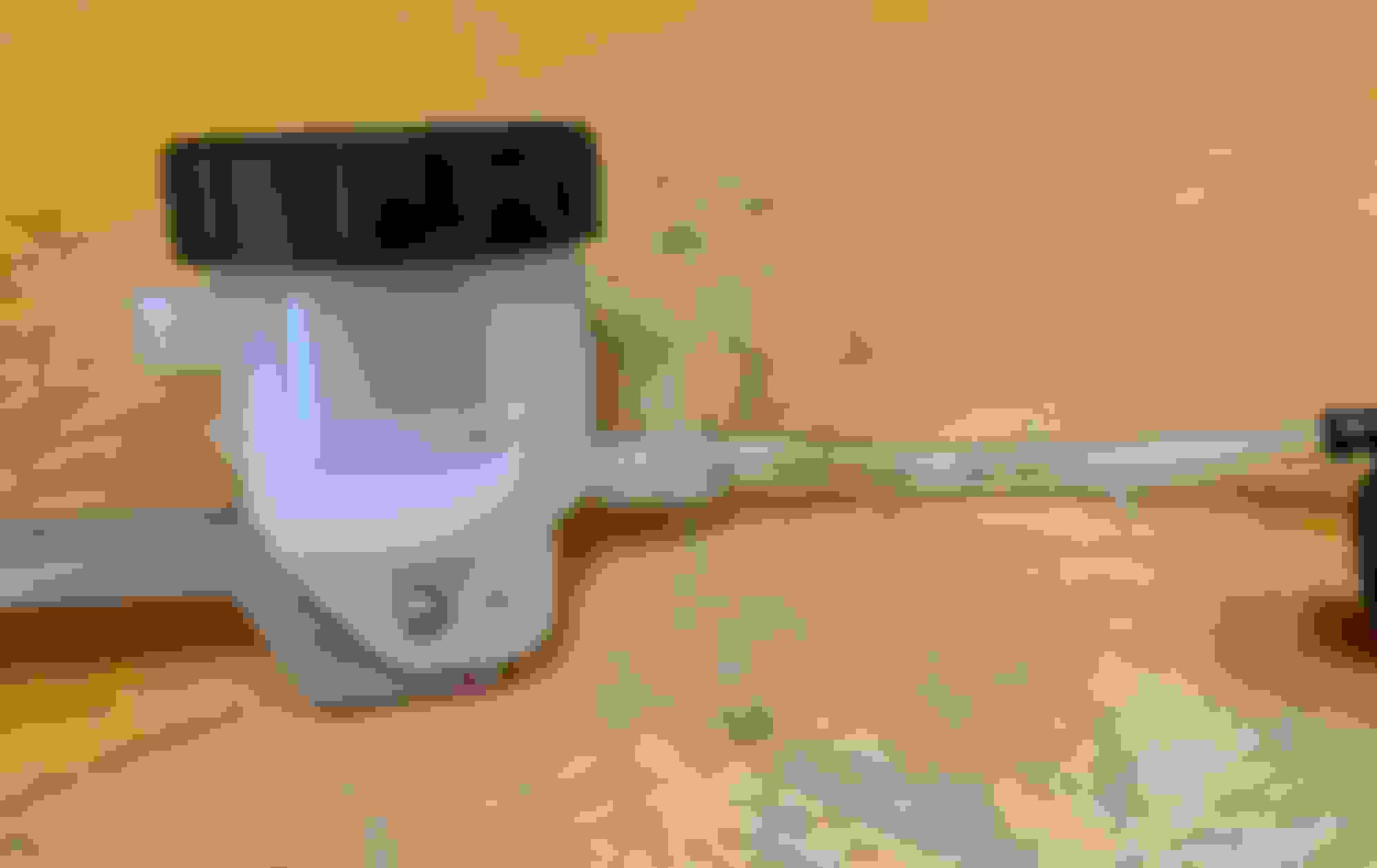
17. Now, to tap the cap, we need to use the 1/8 - 27 NPT tap - either you have it at home or purchase it for this project. Below is the set I purchased - it comes with the tap, and also a 15/64 drill bit as a set. In the photo below, there's also the 6mm (M6) screw that I bought from HomeDepot for mounting the gizmo onto the car later:
18. Here is the most tricky, and most critical portion of this mod project: tap the cap correctly, and not screw this up! - since we only have one cap, if you messed up, you won't be able to finish the project until you buy another one, so be very careful here!
First, use the 15/64" drill bit, drill a whole at the center of the cap. Be careful that do not run the drill too fast to crack the cap, as it's a hard plastic. I found it's easier by clamping the cap on anvil to hold it securely, and use a power drill with a slow speed to start the drilling:
19. Next, use the 1/8-27 tap to tap over that hole. The tricky part is, normally, you would need a special tap tool, which hold the tap vertical and allows you to turn the tap manually and slowly, but since I don't have one, I used a plier to slowly turn the tap, while keeping it straight when going down. Do not use a power drill with a high speed, as that could easily mess up the thread in the tap hole:
20. With the threaded hole being tapped, thread on the 90 degree adapter. Make sure you screw the adapter all the way in, until it just comes out on the other end (insider of the cap):
21. Now we need to put the hose or the tube on the cap and the overflow container. Here's the photo showing the tube that comes with the bleed cap (left), an extra one that also comes with the package (middle), and the same size tube spool bought from Loews (right). As you can see, the tube that was on the cap is too big, and the extra one it comes with the package and the one from Lowes are the same size. Matt had mentioned in the old thread that you wouldn't need to purchase the extra spool tube, and just use the extra one that comes with the package. What I found out was, it's a bit hard to mount the one that came with the package onto the overflow container compare to the tube from Lowes, as I had a hard time pry an opening on the tube wide enough to mount it onto the nipple of the overflow container. I don't know if the materials is any different or not, but I winded up used the tube from Lowes.
You can certainly try just use the tube that comes with the bleed cap package, and if you have good luck to get it onto the container, you can save yourself the extra few bucks of buying another spool from Lowes. But for me, after trying the extra tube a few times, I deformed it with repeated heating and prying and pushing, and in the end, I just cut a piece from the spool I bought, and and got it working. So it saved my day, as otherwise I would have to stop the project and order from Lowes.
22. Here I used the heart gun to mount the tube onto the nipple of the overflow container. It's a bit harder to connect on this end, as the container nipple has a big lock bump, whereas on the 90 degree adapter, it's relatively easy: just heat up the tube, and push it though the adapter, as the lock bump on it is relatively smaller.
23. OK, we are now done with the construction of the entire gizmo!
I took a photo of my finished gizmo before I mounted it on the car, but I made 2 mistakes! - (1) the diaphragm (right green arrow) should have mounted on the plastic holder (left green arrow), and they should be added on the cap for the overflow container. I mistakenly put the diaphragm on the bleed cap (blue arrow), and (2) notice that the tube was just over the locking bump on the container nipple, where it really should have been pushed all the way through to the end of the nipple. The way I put it on, it will cause a minor leak!
24. Using that 6mm (M6) screw from HomeDepot, I mount the gizmo onto the car:
25. Here's how it looks when everything is installed. Looks nice! - very factory-installed look, better than my plastic cup + paper towel temporary "solution", and also better than the fabric or socks "solution":
26. I did a lifting test, and immediately saw there are leaks! Oops! I consulted with Matt, and as I mentioned earlier, I got things mixed up. I should have put the diaphragm onto the overflow container cap, not the bleed cap over the main reservoir. Here I have taken off the diaphragm from the bleed cap, and inserted the that thin gasket (green arrow) which I didn't put it on and caused the leak. The rad arrow shows there was a dripping leak under the overflow container nipple (blue arrow), which was due to the tube wasn't inserted all the way.
27. So, to fix these two issues, first I tool down the gizmo and reheated the tube, and pushed it all the way in. Now it's very tight and secure, no more leaks from that connection:
28. Next, I put the diaphragm over the plastic diaphragm holder that comes with the overflow container, and put them into the cap, and then put it on the container. Here's the 3 pieces that should all go onto the overflow container:
29. OK, now with the mistakes corrected, I installed the gizmo onto the car again, and ran multiple lifting tests. Here's when the lift is up, and as you can see, the fluid level is low:
30. Here's when the lift is lowered, and you can see that the fluid level in the main reservoir is at the MAX line. I did several lifting and lowering operations when the car is parked on a level or near level ground, and the results are similar to these:
31. Now the stress tests: I parked the car on a couple of inclined surface, here is one of them that has a mild slope, and repeated the lifting tests...
32. On a sloped ground, this is when the lift is up. As you can see, due to incline, the fluid is accumulated at the rear end of the main reservoir, and it's already at the MAX level line:
33. When the lift is lowered at this inclined position, the fluid is being pushed to the overflow container. As you can see here, the volume of the fluid gushed over to the overflow container is quite large, almost filled half of the container. Now imagine the scenarios when the lift is operated on an inclined road without this gizmo, and sheer volume of the fluid that's being pushed through the reservoir cap is simply huge, and if this mount shown in the overflow container, or even just half of this amount, is being pushed through the factory diaphragm and cap over the reservoir, it's really going to be leaking all over the place in the car, which would be a disaster!
Now with this "Matt Gizmo", none of this fluid is leaking out. Better yet, when the lift is operated again on a leveled ground or inside garage, the fluid being pushed to the overflow container, will be sucked back into the main reservoir, which means there won't be any fluid loss. Moreover, because the bleed cap we installed on the main reservoir is air-tight (because we put that gasket in the cap), the chance of outside air and moisture getting into the fluid is greatly reduced, which will prolong the life of the fluid, a double win for using this gizmo!
I repeated the tests by parking the car on an even steeper slope road, and operating the lift multiple times, and the whole fix works like a charm, no leaking, and no fluid accumulated in the overflow reservoir after getting the car home with a final lift operation when the car is lowered for the last time inside the garage. Everything worked so perfectly, this solution is going to be the final and permeant solution - unless GM offers a free recall fix with a better solution (which I no longer need to hold my breath waiting for). I have put the front cover back onto the car, and consider this problem is fixed for good!
So, now with the detailed steps of making the gizmo, along with my own mistakes and lessons learned, I hope that many of you will find this is easy to follow, and what not to do to avoid my mistakes, and be inspired to make the same for your beloved C8!
Many thanks to Matt again for coming up with solution! With this done, we can feel safe driving on any roads and operate the lift without worry.
Enjoy and have fun doing this critical mod for you car!
Get job throughout! A couple questions: 1) The overflow reservoir has holes in the diaphragm but the cap itself does not? I guess I'm confused that the diaphragm and plastic diaphragm holder would have vent holes but the cap itself doesn't. It would seem without venting the cap the holes in the diaphragm wouldn't be necessary? 2) The collapsible diaphragm you moved to the reservoir cap, did that come with the bleeder cap you bought or is that the O.E.M. diaphragm from the original O.E.M. tank cap? Thanks!
Last edited by Broken Halo; 02-22-2021 at 08:09 AM.
@bluan (Bill) - Thank you for sharing your very detailed DIY, good job! And thanks also to @MAD Matt for his original "Gizmo" solution concept. I will start collecting components to replicate that mod. -Rick
Last edited by R & K C8; 02-22-2021 at 08:52 AM.
Reason: added (Bill)
Bill, Nice write up. This will help out whomever wishes to replicate the "Gizmo". I'm glad you obtained the same results, with the proper corrections. Thanks for the kudos!
Randy, The cap on the sportbike reservoir is actually vented on the sides. There are two places where there are no threads, opposite one another and virtually do the same thing as the groove/channel in the factory cap. That was the main reason I chose that particular sportbike unit. I want to thank everyone involved in the original post for their suggestions and input. In the end, together, we were able to come up with a relatively inexpensive solution.
. Very detailed instructions. Unfortunately, I'm a klutz when it comes to DIY. Shouldn't the leak be covered under warranty?
@manecda - Yes, "leaky" Front Lift Reservoirs should be covered by warranty, but Chevrolet probably does not have a "fix" yet other than to install a replacement cap which is not effective. It will take a sufficiently large number of C8s Owners formally reporting this problem to Dealer Service to encourage Chevrolet to start working on a proper solution. -Rick
All I can say is Wow. What an amazing job you did coming up with a solution to this problem. I wonder if after people at GM see this if their solution is close if not exactly like the one you just documented.
OP, you are to be commended for putting together such detailed instructions. I can appreciate the time and effort involved. With that said, I’m not spending $70 to “jury-rig” an engineering failure on a $90K car. Chevy can fix the problem under warranty.
While I like all the posts including Matt's, I also have to say, this is really an excellent effort to help anyone who's even thinking of doing this "bluan", Bill. Just excellent. And this takes nothing away from Matt who did most of the ground-laying work; it only adds to his complete project as well. So, to the both of you--- big Kudos! And
Excellent write up
Solution is up there with A O Road's Covers.
FYI, I avoid electrical items at HF, but I have this item and it is as great as any at 4times the price. Save another $20 if you need one. This coupon is expired, but HF repeats all the time. Never pay full price there.
Great detailed description, thank you very much! I may attempt this solution myself. 2 questions though:
1. Is the 90� adapter on the bleeder cap required because there is not enough height above the cap (with the plastic covers in place) to simply run the hose off the nipple that is already on the bleeder cap?
2. Is the original OEM diaphragm from the factory cap not used? I thought the original diaphragm was to be placed in the bleeder cap, it looks like you just have the thin rubber “washer” in the bleeder cap.
Great detailed description, thank you very much! I may attempt this solution myself. 2 questions though:
1. Is the 90� adapter on the bleeder cap required because there is not enough height above the cap (with the plastic covers in place) to simply run the hose off the nipple that is already on the bleeder cap? The 90 degree fitting is needed so the factory surround cover be be reinstalled. There is not enough room to use the bleeder cap "As Is". The existing hose, when bent to a 90, collaspes internally.
2. Is the original OEM diaphragm from the factory cap not used? I thought the original diaphragm was to be placed in the bleeder cap, it looks like you just have the thin rubber �washer� in the bleeder cap.
That is correct. The OEM diaphragm is NOT used in the configuration. The bleeder cap comes with 2 rubber gaskets. The thinner of the two is used in place of the factory diaphragm. The sportbike reservoir is used "As Supplied" with all pieces that come with it configured how it is received. The only thing required is to make a small hole in the rubber diaphragm. Bluan used a 1/16" drill bit. I would advise using a large sewing needle heated with a lighter to pierce the hole as it provides a cleaner and more finished hole that will eliminate any future tearing.
This is unacceptable. This should be done by GM, not the owner (irrespective whether or not the owner "enjoys" doing this type of fix). The average buyer does not have the skill set for this. Still on the fence about the C8 vis a vis the 911? Stuff like this does not help.
Agreed, but some don't want to wait and some love to invent. Some like me will wait with a lower corrected reservoir level. In the bigger picture; Delays, frunk, towers, lift reservoir, are no big deals.
The C8 is still a Game Changer and on 911s and just about every other super car - and that isn't even considering the price difference.
The only thing required is to make a small hole in the rubber diaphragm. Bluan used a 1/16" drill bit. I would advise using a large sewing needle heated with a lighter to pierce the hole as it provides a cleaner and more finished hole that will eliminate any future tearing.
Matt, you had said the purchased reservoir had vents in the cap that came with it. If the diaphragm that came with it didn't have a hole (we have to make one in it) how did the reservoir, as purchased, vent? I'm confused as to why part of the assembly would vent (the cap) but the other component would not (the diaphragm).

 02-22-2021, 03:29 AM


 ), so I did some research and comparison on Amazon, and bought this one, which has temperature adjustment as well as having a display for temperature, very handy feature -
, $38.99
), so I did some research and comparison on Amazon, and bought this one, which has temperature adjustment as well as having a display for temperature, very handy feature -
, $38.99