
Elite Engineering's Catch Can and Clean-Side Oil Separator
 05-01-2014, 04:39 PM
#1
Supporting Vendor
Thread Starter
Member Since: Aug 2003
Location: Beautiful CO
Posts: 3,640
Likes: 0
Received 6 Likes
on
3 Posts
St. jude Donor '14

Part 1
Do it once, and do it right!
We have received a ton of questions regarding the correct installation of a Catch Can on a C7 Stingray with the Z51 option Dry Sump Only.
With all the great improvements General Motors has done with their baffles in both the valve covers and where the crankcase dirty side is evacuated, there is still a lot of oil that enters the Air Intake from (2) two different locations.
#1 The oil sump tank, similar to the C6 Z06 dry sump tank
#2 The Valley Cover (dirty side) - We'll use the Elite E2 Catch Can to address this issue
There are countless images on the Internet of oil found inside a C7's Intake.
For many reasons, we DON'T want to completely delete GM's current PCV System, we just want to improve its functionality and performance.
The 1st thing to address is the Clean-Side. The Clean-side solution addresses that small amount of oil vapor that enters the intake air charge upstream of the throttle body during WOT operation when the intake manifold vacuum is not present.
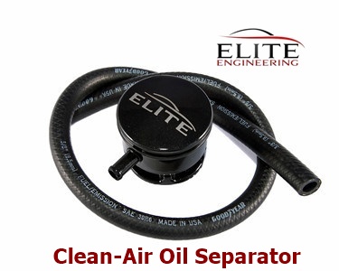
The Clean side solution allows 100% MAF metered air entry while trapping the oil during wide open throttle operation and allowing it to return back into the valve cover as soon as the throttle is lifted.
Simply installs as a direct replacement for your stock Oil Fill Cap allowing you to delete and replace the stock OEM hose.
At 1/2 the cost of the plastic hollow GM unit, our aluminum clean-side separator incorporates an internal coalescing material. Simply unscrew the top for a quick inspection or cleaning.
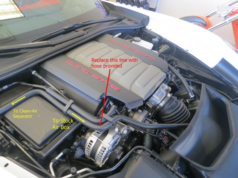
The Passenger's Side Valve Cover has two fittings that join the vent through the drysump tank and also connect to the air box pictured below, this is where the Clean-Air Separator is installed.
The Clean-Side Separator will trap the oil that "burps" and will hold it and prevent it from being ingested. Any oil trapped with find its way back during full vacuum or normal deceleration or idle.
Added to the Elite original Catch Can, or New E2 Catch Can, this is your COMPLETE PCV Oil Ingestion Solution.
Do it once, and do it right!
We have received a ton of questions regarding the correct installation of a Catch Can on a C7 Stingray with the Z51 option Dry Sump Only.
With all the great improvements General Motors has done with their baffles in both the valve covers and where the crankcase dirty side is evacuated, there is still a lot of oil that enters the Air Intake from (2) two different locations.
#1 The oil sump tank, similar to the C6 Z06 dry sump tank
#2 The Valley Cover (dirty side) - We'll use the Elite E2 Catch Can to address this issue
There are countless images on the Internet of oil found inside a C7's Intake.
For many reasons, we DON'T want to completely delete GM's current PCV System, we just want to improve its functionality and performance.
The 1st thing to address is the Clean-Side. The Clean-side solution addresses that small amount of oil vapor that enters the intake air charge upstream of the throttle body during WOT operation when the intake manifold vacuum is not present.
The Clean side solution allows 100% MAF metered air entry while trapping the oil during wide open throttle operation and allowing it to return back into the valve cover as soon as the throttle is lifted.
Simply installs as a direct replacement for your stock Oil Fill Cap allowing you to delete and replace the stock OEM hose.
At 1/2 the cost of the plastic hollow GM unit, our aluminum clean-side separator incorporates an internal coalescing material. Simply unscrew the top for a quick inspection or cleaning.
The Passenger's Side Valve Cover has two fittings that join the vent through the drysump tank and also connect to the air box pictured below, this is where the Clean-Air Separator is installed.
The Clean-Side Separator will trap the oil that "burps" and will hold it and prevent it from being ingested. Any oil trapped with find its way back during full vacuum or normal deceleration or idle.
Added to the Elite original Catch Can, or New E2 Catch Can, this is your COMPLETE PCV Oil Ingestion Solution.

Last edited by Elite Engineering; 05-09-2014 at 03:46 PM.
 05-01-2014, 04:40 PM
#2
Supporting Vendor
Thread Starter
Member Since: Aug 2003
Location: Beautiful CO
Posts: 3,640
Likes: 0
Received 6 Likes
on
3 Posts
St. jude Donor '14
Part 2
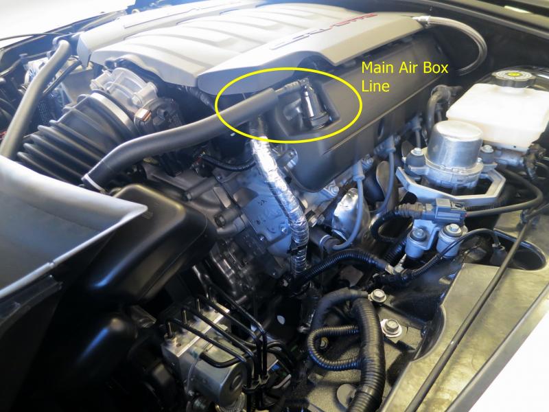
Now addressing the real problem area, the Dirty Side. Shown below, the filtered Mass Air Flow (MAF) fresh air enters the driver's side valve cover through this Main Air Box Line shown above. We'll leave this line untouched.
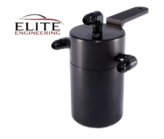
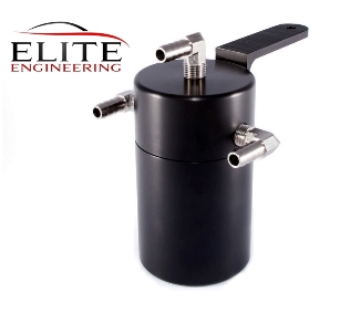
The best set-up/installation will utilize the 2nd Generation E2 Catch Can with Dual Exit Ports and (2x) Check Valves. Shown below with Electroless Nickel Fittings or Black AN Fittings.
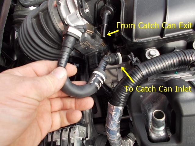
This U shaped fitting shown below runs from the Intake Manifold Vacuum Barb down to the Valley Cover Barb. We'll remove this U-shaped fitting and Splice in the E2 Catch Can here.
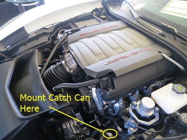
Mount the E2 Catch Can here, using the supplied G8 Bracket
Now addressing the real problem area, the Dirty Side. Shown below, the filtered Mass Air Flow (MAF) fresh air enters the driver's side valve cover through this Main Air Box Line shown above. We'll leave this line untouched.
The best set-up/installation will utilize the 2nd Generation E2 Catch Can with Dual Exit Ports and (2x) Check Valves. Shown below with Electroless Nickel Fittings or Black AN Fittings.
This U shaped fitting shown below runs from the Intake Manifold Vacuum Barb down to the Valley Cover Barb. We'll remove this U-shaped fitting and Splice in the E2 Catch Can here.
Mount the E2 Catch Can here, using the supplied G8 Bracket
Last edited by Elite Engineering; 05-01-2014 at 04:51 PM.
05-01-2014, 04:52 PM
#3
Supporting Vendor
Thread Starter
Member Since: Aug 2003
Location: Beautiful CO
Posts: 3,640
Likes: 0
Received 6 Likes
on
3 Posts
St. jude Donor '14
Part 3
Now let's look at the connections on the (2) Exit Port Catch Can, pictured below:
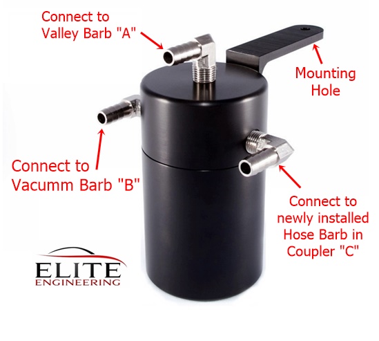
Now we simply connect the Center Port on the E2 Catch Can to the Valley Barb "A" (and since it already is a check valve, no additional valve need be installed here)
Now Connect (1) of the Side Exit Ports to the Vacuum Barb "B" left open after removing the U shaped stock tube, WITH a checkvalve flowing away from the can (this is to ensure no mixing and reversion)
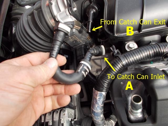
Finally, the 2nd Exit Port will connect to the newly drilled and installed 3/8" Hose Barb fitting in the Stock OEM Coupler "C"
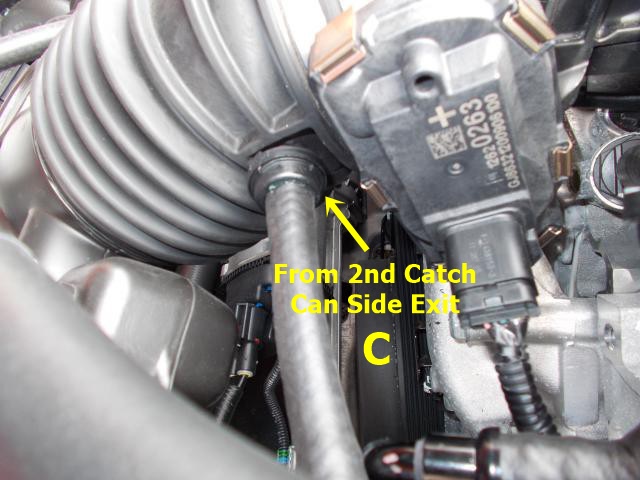
This will provide suction for evacuation while in WOT operating mode when vacuum inside the Intake Manifold doesn't exist.
This setup will now ensure the flow is always traveling in the right direction.
Do it once, and do it right!
Now let's look at the connections on the (2) Exit Port Catch Can, pictured below:
Now we simply connect the Center Port on the E2 Catch Can to the Valley Barb "A" (and since it already is a check valve, no additional valve need be installed here)
Now Connect (1) of the Side Exit Ports to the Vacuum Barb "B" left open after removing the U shaped stock tube, WITH a checkvalve flowing away from the can (this is to ensure no mixing and reversion)
Finally, the 2nd Exit Port will connect to the newly drilled and installed 3/8" Hose Barb fitting in the Stock OEM Coupler "C"
This will provide suction for evacuation while in WOT operating mode when vacuum inside the Intake Manifold doesn't exist.
This setup will now ensure the flow is always traveling in the right direction.
Do it once, and do it right!
Last edited by Elite Engineering; 05-02-2014 at 11:42 AM.
 05-01-2014, 06:19 PM
#6
Supporting Vendor
Thread Starter
Member Since: Aug 2003
Location: Beautiful CO
Posts: 3,640
Likes: 0
Received 6 Likes
on
3 Posts
St. jude Donor '14
For many reasons, we don't to remove the current PCV System, we just want to improve its function.
Here's a great video for more information on the PCV System:
Here's a great video for more information on the PCV System:
 05-01-2014, 09:48 PM
#8
Instructor


Member Since: Jan 2011
Posts: 121
Likes: 0
Received 0 Likes
on
0 Posts
Part 3
Now let's look at the connections on the (2) Exit Port Catch Can, pictured below:
Attachment 47791016
Now we simply connect the Center Port on the E2 Catch Can to the Valley Barb "A" (and since it already is a check valve, no additional valve need be installed here)
Now Connect (1) of the Side Exit Ports to the Vacuum Barb "B" left open after removing the U shaped stock tube, WITH a checkvalve flowing away from the can (this is to ensure no mixing and reversion)
Attachment 47791017
Finally, the 2nd Exit Port will connect to the newly drilled and installed 3/8" Hose Barb fitting in the Stock OEM Coupler "C"
Attachment 47791020
This will provide suction for evacuation while in WOT operating mode when vacuum inside the Intake Manifold doesn't exist.
This setup will now ensure the flow is always traveling in the right direction.
Do it once, and do it right!
05-01-2014, 10:06 PM
#9

So this seems to be somewhat different than the install instructions for the 2 port catch can. If someone purchased the 2 port catch can with a Z51, is this an appropriate solution? How should the install work and what about check valves (given it appears they are deleted in the instructions previously posted for the 2 port can).
It would be great if you could clarify as there seems to be a lot of confusion.
It would be great if you could clarify as there seems to be a lot of confusion.


 05-02-2014, 01:20 AM
#12
05-02-2014, 08:01 AM
#13
Advanced

Member Since: Jul 2011
Location: Parker Pa
Posts: 58
Likes: 0
Received 0 Likes
on
0 Posts
Perhaps Elite could supply us a list of what exactly is need for a:
1) Base C7
2) Z51 without Clean Line Separator
3) Z51 with Clean Line Separator
Also include if any additional check valves are needed (single/double).
Last edited by ajkelly; 05-02-2014 at 08:04 AM.
05-02-2014, 08:06 AM
#14
Le Mans Master


I am very interested in this but want to make sure that I purchase the correct one for the Z51, are there two pieces that you buy? Finally I think most folks will agree, the documentation needs to be very clear and accurate, can you please post or provide a url that can clearly provides installation directions for a Z51 install. Thank you.
05-02-2014, 08:51 AM
#15
Racer


 05-02-2014, 09:01 AM
#16
Moderator


Here's the photo that does not show in "Part 3":
 05-02-2014, 11:49 AM
#17
Drifting

Elite Engineering needs to rewrite or edit the entire post. To many unanswered questions, which leads to problems for all. They NEED to have pictures of the correct system completely installed. Do it right.
05-02-2014, 11:50 AM
#18
Supporting Vendor
Thread Starter
Member Since: Aug 2003
Location: Beautiful CO
Posts: 3,640
Likes: 0
Received 6 Likes
on
3 Posts
St. jude Donor '14
The C7 being direct injection is very subject to the intake valve coking issues (google search: " Direct Injection Intake valve coking" and click on images) as all DI engines have this issue.
GM has greatly improved the oil separating function of the valve cover and valley cover for 2014, but it is still an issue so ALL oil and related blow-by compounds must be trapped before they can enter the intake air charge....far more critical than ever in the past with any GM V8 before....so this is new to some that may not have been intimate w/DI engines (GM 3.6 v6 DI since 2008).
The Dry-Sump (Z51 option) is especially prone to this, not as much an issue with the Wet-Sump.
The importance of the dual outlets on the Catch Can is that many vette owners will run at WOT from time to time, and during that time there is zero measurable vacuum present in the intake manifold to maintain the correct direction of PCV flow, so adding that extra barb allows the flow to maintain proper direction because at WOT there is a good amount of suction just upstream of the Throttle Body where the reversion pulses do not reach (until over say 8,000 RPM which they won't reach).
You only need the check valve on the intake manifold side in this case.
05-02-2014, 01:58 PM
#19
Supporting Vendor
Thread Starter
Member Since: Aug 2003
Location: Beautiful CO
Posts: 3,640
Likes: 0
Received 6 Likes
on
3 Posts
St. jude Donor '14
Bummer, same here. Wrong one ordered, single exit port is being delivered by FedEx today. When I ordered there was no option for Z51 or base, just said 2014 C7. Guess we'll get a chance to see how the return policy works. Now I need to be sure to get the correct check valve ordered.
Perhaps Elite could supply us a list of what exactly is need for a:
1) Base C7
2) Z51 without Clean Line Separator
3) Z51 with Clean Line Separator
Also include if any additional check valves are needed (single/double).
Perhaps Elite could supply us a list of what exactly is need for a:
1) Base C7
2) Z51 without Clean Line Separator
3) Z51 with Clean Line Separator
Also include if any additional check valves are needed (single/double).
1) Base C7
- Standard Catch Can with Single Exit Port, No Check Valve
- Clean-Side Separator is always a good option
2) Z51 with Dry Sump
-2nd Gen E2 Catch Can with two Exit Ports
- two check valves, one on each Catch Can Exit fitting
- Clean-Side Separator
Last edited by Elite Engineering; 05-02-2014 at 02:19 PM.
05-02-2014, 02:05 PM
#20
Team Owner


Member Since: Aug 2007
Location: I live my life by 2 rules. 1) Never share everything you know. 2)
Posts: 136,148
Received 2,402 Likes
on
1,366 Posts
St. Jude Donor '11-'12-'13, '16-'17-'18

We will update our website purchasing to make this easier, but this is what you need:
1) Base C7
- Standard Catch Can with Single Exit Port, No Check Valve
- Clean-Side Separator is always a good option
2) Z51 with Dry Sump
-2nd Gen E2 Catch Can with two Exit Ports
- two check valves, one on each Catch Can Exit fitting
- Clean-Side Separator
3) Z51 with Wet Sump
-2nd Gen E2 Catch Can with two Exit Ports
- two check valves, one on each Catch Can Exit fitting
- Clean-Side Separator is always a good option