
[Z06] Stage II LS7 cylinder heads - A visual guide to valve guide wear and CNC upgrades
 06-30-2013, 01:17 PM
#261


The resonant frequency of a valve or more likely the complete valvetrain assembly (valve, spring, rocker arm, pushrod) may be indicated by the bounce peak we see on the plots provided (this is a little over my head so I'm guesstimating quite a bit on that). If you change any of those components, the resonant frequency will probably change.
 06-30-2013, 01:23 PM
#262
I am fairly sure that float could lead to PTV contact, since my understanding of float is that the spring partially collapses and this could very well leave the exhaust valve hanging open by the .300" or so necessary for contact when the piston comes up to TDC.
06-30-2013, 01:24 PM
#263
I see.
So what is the resonant frequency of the REV Extreme X1137 exhaust valve?
Thanks.
The resonant frequency of a valve or more likely the complete valvetrain assembly (valve, spring, rocker arm, pushrod) may be indicated by the bounce peak we see on the plots provided (this is a little over my head so I'm guesstimating quite a bit on that). If you change any of those components, the resonant frequency will probably change.
Last edited by '06 Quicksilver Z06; 06-30-2013 at 01:32 PM.
06-30-2013, 03:13 PM
#264
Burning Brakes


He said they weren't measuring spring resonance. Many things have a resonant frequency, including a valve. Operation at the resonant frequency causes stress levels to skyrocket.
The resonant frequency of a valve or more likely the complete valvetrain assembly (valve, spring, rocker arm, pushrod) may be indicated by the bounce peak we see on the plots provided (this is a little over my head so I'm guesstimating quite a bit on that). If you change any of those components, the resonant frequency will probably change.
The resonant frequency of a valve or more likely the complete valvetrain assembly (valve, spring, rocker arm, pushrod) may be indicated by the bounce peak we see on the plots provided (this is a little over my head so I'm guesstimating quite a bit on that). If you change any of those components, the resonant frequency will probably change.
 06-30-2013, 05:30 PM
#266
Ferrea was supposed to come up with a hollow LS7 exhaust valve weighing in at around 89 grams... dunno if they ever have released it, but it really doesn't matter since the consensus here (by volume at least) is that hollow valves are simply unsuitable and/or are to be feared.
It should be noted that Manley makes five different grades of valves, so just having a Manley valve doesn't mean a whole lot. For the LS7 exhaust, they make two grades -- XH-428 and XH-432. Some interesting technical reading in their 2013 valve catalog, but since it is an 'advertisement' I have been advised that none of it may be true. YMMV . . . . .
http://www.manleyperformance.com/dl/2013/valves.pdf
.
Last edited by Mark2009; 06-30-2013 at 05:47 PM.
06-30-2013, 06:13 PM
#267
Melting Slicks

WCCH uses the REV LS7 Exhaust Valve 1.615" 8mm 5.230" OAL w/.290 tip. with a cost of $138 for 8 of them.
06-30-2013, 07:59 PM
#269
Racer


Member Since: Oct 2005
Posts: 365
Likes: 0
Received 0 Likes
on
0 Posts

If the LS7 sits there stationary and never gets fired up, then yes, the above is a good comparison (except the critical load on a valve stem is tensile instead of compression). However, if the load is dynamic rather than static, the outcome can be quite different.
For dynamic tensile loading on a metal part, fatigue is usually the cause of failure. One parameter which has a major contribution to fatigue life cycle limit is the ratio between applied tensile stress and the material's allowable tensile stress. A valve in an engine is a classic example of dynamic tensile loading. The biggest different between a solid stem valve vs. a hollow valve is the cross sectional area at the stem. A quick use of a calculator will indicate that the solid stem valve has a HUGE percentage increase in this cross sectional area. Since stress is defined as applied force divided by the part's cross sectional area, the resultant tensile stress at the stem of a solid stem valve is "SUBSTANTIALLY" lower than a "thin wall" hollow stem. At some really low level of tensile stress, the part will basically last forever. This is how engineers designed most of their parts during the early stage of the industrial revolution. The typical rule of thumb is that if a part's tensile stress is 50% or higher compare to the material's allowable tensile stress (at service, which varies depending on the service temperature of the material), the part will "eventually" fail after X number of cycles. So, one way to increase a part's fatigue life is to either put in a bigger part (bigger cross sectional area to lower the tensile stress) or increase the material's strength. Most of the stainless steel materials used for making exhaust valves have very similar mechanical properties. At elevated temperature where these valves run at, I doubt one can suddenly find a SS material that has a 30% higher allowable stress value. However, it is quite easy to increase the stem wall thickness to lower the tensile stress to 50% of what the OEM valve runs at. Why GM engineers didn't go with a slightly thicker wall to get a larger safety margin is beyond my comprehension. With an aftermarket solid stem, the resultant stress is so much lower, I would consider it almost impossible to fail via fatigue cycling. This is the reason why I have recently switched over to solid stem valves also (haven't entered my name onto the list yet).
The thing about resonance frequency is that as long as you are just crossing it occasionally and not staying at that frequency for long periods of time. The stress is tolerable, if the part has a reasonable large safety margin.
06-30-2013, 09:08 PM
#270
Team Owner

According to who? That's quite a lofty claim.......
Just because a shop is popular in the "car enthusiast forum world", does not necessarily mean, well - shiit.
Hollow stemmed valves should feel flimsy and light. They are designed to be light, for a reason. Doesn�t mean they are not robust or will not take abuse. A steel pipe will provide enough support to hold up a roof structure, just like a solid piece of round steel the same dimension. The benefit the steel pipe has over the solid round stock is a reduction in weight.
All three times I have gone down to WCCH and spoke to Richard I have had to wait for him to get off the phone with some vender discussing issues beyond my understanding. His shop has rows and rows of cylinder heads. Their high tech machinery includes those you once discussed as being the best. I see countless work orders both private and from Vendors I recognize including Katech. When he tells me he does heads from all over the world I don't doubt him. Even one of our members used to use him for his motorcycle heads. The guy has a very long history and outstanding reputation. If he is not all that, I don't hear anyone saying otherwise or mentioning an equal peer.
As far as the hollow stem goes. I'm sorry but when I'm being schooled about what possible issues are causing exhaust valves to fail and I'm holding a hollow stem in one hand and looking at that very thin wall while comparing to the other hand holding a solid valve, I am going to go with the solid valve not just because it makes common sense but because the expert in the field is telling me thats what he would put in my car


DH
06-30-2013, 10:55 PM
#271
Drifting


Member Since: May 2011
Posts: 1,337
Likes: 0
Received 0 Likes
on
0 Posts
If the LS7 sits there stationary and never gets fired up, then yes, the above is a good comparison (except the critical load on a valve stem is tensile instead of compression). However, if the load is dynamic rather than static, the outcome can be quite different.
For dynamic tensile loading on a metal part, fatigue is usually the cause of failure. One parameter which has a major contribution to fatigue life cycle limit is the ratio between applied tensile stress and the material's allowable tensile stress. A valve in an engine is a classic example of dynamic tensile loading. The biggest different between a solid stem valve vs. a hollow valve is the cross sectional area at the stem. A quick use of a calculator will indicate that the solid stem valve has a HUGE percentage increase in this cross sectional area. Since stress is defined as applied force divided by the part's cross sectional area, the resultant tensile stress at the stem of a solid stem valve is "SUBSTANTIALLY" lower than a "thin wall" hollow stem. At some really low level of tensile stress, the part will basically last forever. This is how engineers designed most of their parts during the early stage of the industrial revolution. The typical rule of thumb is that if a part's tensile stress is 50% or higher compare to the material's allowable tensile stress (at service, which varies depending on the service temperature of the material), the part will "eventually" fail after X number of cycles. So, one way to increase a part's fatigue life is to either put in a bigger part (bigger cross sectional area to lower the tensile stress) or increase the material's strength. Most of the stainless steel materials used for making exhaust valves have very similar mechanical properties. At elevated temperature where these valves run at, I doubt one can suddenly find a SS material that has a 30% higher allowable stress value. However, it is quite easy to increase the stem wall thickness to lower the tensile stress to 50% of what the OEM valve runs at. Why GM engineers didn't go with a slightly thicker wall to get a larger safety margin is beyond my comprehension. With an aftermarket solid stem, the resultant stress is so much lower, I would consider it almost impossible to fail via fatigue cycling. This is the reason why I have recently switched over to solid stem valves also (haven't entered my name onto the list yet).
The thing about resonance frequency is that as long as you are just crossing it occasionally and not staying at that frequency for long periods of time. The stress is tolerable, if the part has a reasonable large safety margin.
glad to see you post ...been a while
07-01-2013, 01:59 AM
#272
Team Owner
If the LS7 sits there stationary and never gets fired up, then yes, the above is a good comparison (except the critical load on a valve stem is tensile instead of compression). However, if the load is dynamic rather than static, the outcome can be quite different.
For dynamic tensile loading on a metal part, fatigue is usually the cause of failure. One parameter which has a major contribution to fatigue life cycle limit is the ratio between applied tensile stress and the material's allowable tensile stress. A valve in an engine is a classic example of dynamic tensile loading. The biggest different between a solid stem valve vs. a hollow valve is the cross sectional area at the stem. A quick use of a calculator will indicate that the solid stem valve has a HUGE percentage increase in this cross sectional area. Since stress is defined as applied force divided by the part's cross sectional area, the resultant tensile stress at the stem of a solid stem valve is "SUBSTANTIALLY" lower than a "thin wall" hollow stem. At some really low level of tensile stress, the part will basically last forever. This is how engineers designed most of their parts during the early stage of the industrial revolution. The typical rule of thumb is that if a part's tensile stress is 50% or higher compare to the material's allowable tensile stress (at service, which varies depending on the service temperature of the material), the part will "eventually" fail after X number of cycles. So, one way to increase a part's fatigue life is to either put in a bigger part (bigger cross sectional area to lower the tensile stress) or increase the material's strength. Most of the stainless steel materials used for making exhaust valves have very similar mechanical properties. At elevated temperature where these valves run at, I doubt one can suddenly find a SS material that has a 30% higher allowable stress value. However, it is quite easy to increase the stem wall thickness to lower the tensile stress to 50% of what the OEM valve runs at. Why GM engineers didn't go with a slightly thicker wall to get a larger safety margin is beyond my comprehension. With an aftermarket solid stem, the resultant stress is so much lower, I would consider it almost impossible to fail via fatigue cycling. This is the reason why I have recently switched over to solid stem valves also (haven't entered my name onto the list yet).
The thing about resonance frequency is that as long as you are just crossing it occasionally and not staying at that frequency for long periods of time. The stress is tolerable, if the part has a reasonable large safety margin.
For dynamic tensile loading on a metal part, fatigue is usually the cause of failure. One parameter which has a major contribution to fatigue life cycle limit is the ratio between applied tensile stress and the material's allowable tensile stress. A valve in an engine is a classic example of dynamic tensile loading. The biggest different between a solid stem valve vs. a hollow valve is the cross sectional area at the stem. A quick use of a calculator will indicate that the solid stem valve has a HUGE percentage increase in this cross sectional area. Since stress is defined as applied force divided by the part's cross sectional area, the resultant tensile stress at the stem of a solid stem valve is "SUBSTANTIALLY" lower than a "thin wall" hollow stem. At some really low level of tensile stress, the part will basically last forever. This is how engineers designed most of their parts during the early stage of the industrial revolution. The typical rule of thumb is that if a part's tensile stress is 50% or higher compare to the material's allowable tensile stress (at service, which varies depending on the service temperature of the material), the part will "eventually" fail after X number of cycles. So, one way to increase a part's fatigue life is to either put in a bigger part (bigger cross sectional area to lower the tensile stress) or increase the material's strength. Most of the stainless steel materials used for making exhaust valves have very similar mechanical properties. At elevated temperature where these valves run at, I doubt one can suddenly find a SS material that has a 30% higher allowable stress value. However, it is quite easy to increase the stem wall thickness to lower the tensile stress to 50% of what the OEM valve runs at. Why GM engineers didn't go with a slightly thicker wall to get a larger safety margin is beyond my comprehension. With an aftermarket solid stem, the resultant stress is so much lower, I would consider it almost impossible to fail via fatigue cycling. This is the reason why I have recently switched over to solid stem valves also (haven't entered my name onto the list yet).
The thing about resonance frequency is that as long as you are just crossing it occasionally and not staying at that frequency for long periods of time. The stress is tolerable, if the part has a reasonable large safety margin.
DH
07-01-2013, 08:42 AM
#273
The LS7 initially used a wall thickness of .035 (hobbyist measurement), an increase of 13% over the apparently trouble free LS6.
Circa 2/2008, most likely concurring with a part number change, the LS7 exhaust valve wall thickness was increased to .042 (again, hobbyist measurement), an increase of 20% over the original LS7 valve and an increase of 35% over the apparently trouble free LS6. Edit: A thread on the LS7 valve measurements is at: http://forums.corvetteforum.com/c6-z...issection.html
The underlined part of your quote implies that you know what the design stresses are and what the limits of the valves are, and that those limits are insufficient. Can you share those numbers?
Or are you just assuming that since we have a rash of broken valves that the design is faulty/weak for normal in-spec operation?
.
Last edited by Mark2009; 07-01-2013 at 09:32 AM. Reason: Added link
07-01-2013, 08:55 AM
#274
Burning Brakes

Actually they did. The LS6 sodium exhaust valve, which seemingly has no issues at all, used a wall thickness of .031, IIRC (I have it in a press release photo op somewhere).
The LS7 initially used a wall thickness of .035 (hobbyist measurement), an increase of 13% over the apparently trouble free LS6.
Circa 2/2008, most likely concurring with a part number change, the LS7 exhaust valve wall thickness was increased to .042 (again, hobbyist measurement), an increase of 20% over the original LS7 valve and an increase of 35% over the apparently trouble free LS6.
The underlined part of your quote implies that you know what the design stresses are and what the limits of the valves are, and that those limits are insufficient. Can you share those numbers?
Or are you just assuming that since we have a rash of broken valves that the design is faulty/weak for normal in-spec operation?
07-01-2013, 10:04 AM
#275
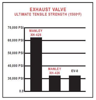
EV-8 is apparently the typical stainless steel alloy used for generic exhaust valves. I'm unsure exactly what alloy Manley is using for the XH-428, but I doubt it is Inconel since that is apparently what is used on their XH-432 (which is priced accordingly at ~$59 ea.), altho they call it XtremeAlloy. For reference, the XH-428 shown in the graph above is priced at $30 ea. (these are prices for the LS7 version, solid stem, p/n 11679 for the XH-428 and 11687 for the XH-432).
Last edited by Mark2009; 07-01-2013 at 10:07 AM.
07-01-2013, 10:11 AM
#276
07-01-2013, 10:45 AM
#277
I would think that bounce would be as bad or perhaps worse than float when it comes to stress on the valve but I simply could not say with any level of conviction.
I am fairly sure that float could lead to PTV contact, since my understanding of float is that the spring partially collapses and this could very well leave the exhaust valve hanging open by the .300" or so necessary for contact when the piston comes up to TDC.
I am fairly sure that float could lead to PTV contact, since my understanding of float is that the spring partially collapses and this could very well leave the exhaust valve hanging open by the .300" or so necessary for contact when the piston comes up to TDC.
Bounce is detrimental because there is no resistance from the lifter/pushrod and rocker assembly to moderate closing velocity and the valve head will slam against the seat with full spring load at full velocity. Once the valve hits the seat, shock load is transferred to the spring via the locks retainer and stem. The valve then bounces on the seat multiple times. Something has to give if this condition is unabated. The head can separate, the keepers can fail, the retainer can fail, spring dampers can fail, springs can break, spring shims can fail, and probably a few other things I am overlooking. Under normal (desirable) conditions, the lifter will remain in contact with the lobe, and the valve will land on the seat in controlled manner whilst the lifter is following the cam lobe�s closing ramp, with a graceful exit off the flank to the heel. One or two bounces in the .005� range is fairly normal at high (+6000) rpm. Any more than that, repeated time and time again, something will eventually give. A change in the valve train must be made to prevent this scenario. Bounce is not generally noted on a dyno unless it exceeds roughly .015�, depending on air flow characteristics at the port. At, or around .015� on the exhaust side, a loss of vacuum in the intake can be seen, and on the intake side, a reduction in power and possible engine stall will occur from the pressure wave into the intake port. The generally accepted gross amount of bounce to stay under is .015�, and any more than that amount will most assuredly result in component failure. Bounce limits between .005� and .015� is often debated, however, .005� is widely accepted as the maximum amount for performance related reasons.
If the LS7 sits there stationary and never gets fired up, then yes, the above is a good comparison (except the critical load on a valve stem is tensile instead of compression). However, if the load is dynamic rather than static, the outcome can be quite different.
For dynamic tensile loading on a metal part, fatigue is usually the cause of failure. One parameter which has a major contribution to fatigue life cycle limit is the ratio between applied tensile stress and the material's allowable tensile stress. A valve in an engine is a classic example of dynamic tensile loading. The biggest different between a solid stem valve vs. a hollow valve is the cross sectional area at the stem. A quick use of a calculator will indicate that the solid stem valve has a HUGE percentage increase in this cross sectional area. Since stress is defined as applied force divided by the part's cross sectional area, the resultant tensile stress at the stem of a solid stem valve is "SUBSTANTIALLY" lower than a "thin wall" hollow stem. At some really low level of tensile stress, the part will basically last forever. This is how engineers designed most of their parts during the early stage of the industrial revolution. The typical rule of thumb is that if a part's tensile stress is 50% or higher compare to the material's allowable tensile stress (at service, which varies depending on the service temperature of the material), the part will "eventually" fail after X number of cycles. So, one way to increase a part's fatigue life is to either put in a bigger part (bigger cross sectional area to lower the tensile stress) or increase the material's strength. Most of the stainless steel materials used for making exhaust valves have very similar mechanical properties. At elevated temperature where these valves run at, I doubt one can suddenly find a SS material that has a 30% higher allowable stress value. However, it is quite easy to increase the stem wall thickness to lower the tensile stress to 50% of what the OEM valve runs at. Why GM engineers didn't go with a slightly thicker wall to get a larger safety margin is beyond my comprehension. With an aftermarket solid stem, the resultant stress is so much lower, I would consider it almost impossible to fail via fatigue cycling. This is the reason why I have recently switched over to solid stem valves also (haven't entered my name onto the list yet).
The thing about resonance frequency is that as long as you are just crossing it occasionally and not staying at that frequency for long periods of time. The stress is tolerable, if the part has a reasonable large safety margin.
For dynamic tensile loading on a metal part, fatigue is usually the cause of failure. One parameter which has a major contribution to fatigue life cycle limit is the ratio between applied tensile stress and the material's allowable tensile stress. A valve in an engine is a classic example of dynamic tensile loading. The biggest different between a solid stem valve vs. a hollow valve is the cross sectional area at the stem. A quick use of a calculator will indicate that the solid stem valve has a HUGE percentage increase in this cross sectional area. Since stress is defined as applied force divided by the part's cross sectional area, the resultant tensile stress at the stem of a solid stem valve is "SUBSTANTIALLY" lower than a "thin wall" hollow stem. At some really low level of tensile stress, the part will basically last forever. This is how engineers designed most of their parts during the early stage of the industrial revolution. The typical rule of thumb is that if a part's tensile stress is 50% or higher compare to the material's allowable tensile stress (at service, which varies depending on the service temperature of the material), the part will "eventually" fail after X number of cycles. So, one way to increase a part's fatigue life is to either put in a bigger part (bigger cross sectional area to lower the tensile stress) or increase the material's strength. Most of the stainless steel materials used for making exhaust valves have very similar mechanical properties. At elevated temperature where these valves run at, I doubt one can suddenly find a SS material that has a 30% higher allowable stress value. However, it is quite easy to increase the stem wall thickness to lower the tensile stress to 50% of what the OEM valve runs at. Why GM engineers didn't go with a slightly thicker wall to get a larger safety margin is beyond my comprehension. With an aftermarket solid stem, the resultant stress is so much lower, I would consider it almost impossible to fail via fatigue cycling. This is the reason why I have recently switched over to solid stem valves also (haven't entered my name onto the list yet).
The thing about resonance frequency is that as long as you are just crossing it occasionally and not staying at that frequency for long periods of time. The stress is tolerable, if the part has a reasonable large safety margin.
Vibration, including resonance and harmonics are much too complicated for me to discuss. I get confused and a raging headache. What I have been taught, is that when the valve slams shut, it starts a chain of events that will ultimately cause the valve to chatter on the seat. Maybe Jwingo can explain this, if he�s paying attention to this thread.
Michael
All three times I have gone down to WCCH and spoke to Richard I have had to wait for him to get off the phone with some vender discussing issues beyond my understanding. His shop has rows and rows of cylinder heads. Their high tech machinery includes those you once discussed as being the best. I see countless work orders both private and from Vendors I recognize including Katech. When he tells me he does heads from all over the world I don't doubt him. Even one of our members used to use him for his motorcycle heads. The guy has a very long history and outstanding reputation. If he is not all that, I don't hear anyone saying otherwise or mentioning an equal peer.
As far as the hollow stem goes. I'm sorry but when I'm being schooled about what possible issues are causing exhaust valves to fail and I'm holding a hollow stem in one hand and looking at that very thin wall while comparing to the other hand holding a solid valve, I am going to go with the solid valve not just because it makes common sense but because the expert in the field is telling me thats what he would put in my car
DH
I was only suggesting that Richard may not be as you said, �the best in the business�. I have no reason to think he is not very good at what he does. Having said that, I am quite certain that there are many cylinder head professionals who be more than willing to go head to head with him at the completion level.
Common sense to me is to run the lightest valve train that I can on a 7000 rpm engine, and to not add weight unless it is absolutely necessary. This is not a truck motor, it�s a 7000 rpm small block with big block CID. If a stronger valve is determined to be necessary, I will run a solid stem Titanium exhaust valve and Mold Star 90 seats to improve flux transfer to the seat to possibly overcome what was lost by removing the stem cooling the sodium filled stem provided.
Would you rather use a solid aluminum bat or a hollow bat?
07-01-2013, 01:11 PM
#278
Le Mans Master


Valve float occurs after the lifter is lofted off the nose of the cam lobe and there is inadequate spring force to overcome the inertia of the moving weight of the valve package and rocker mass (and to a lesser degree, pushrod and lifter mass). The valve will hang – float, without movement for a brief moment. The cam lobe however does not stop moving and tension between the lobe the rocker is relieved, often resulting in the lifter losing contact with lobe altogether. During this brief period of time, a hydraulic lifter will “pump up” because there is not enough load on the lifter plunger spring to prevent it from expanding, allowing pressurized oil to fill the lifter body under the plunger. Eventually the valve spring expands, pulling the valve to the seat, as well as overcoming rocker inertia, driving the pushrod and lifter to the lobe. A double whammy occurs during this scenario; a valve that is refusing to go shut from inadequate spring pressure and a lifter that is now full of oil, taking up a portion, or all, of the lifter pre-load that was available, reducing PTV clearance by the amount of preload that was available. Depending on the hang time in which the valve refused to go closed and engine speed, which is normally in the +6000 rpm range, a very high likelihood of PTV contact will occur. As the valve is at an angle to the piston bore, the valve will bind in the guide, bending it, even if there remains slack in the valve train. The exhaust valve is more prone to PTV contact by virtue of its relative position to the piston during the exhaust stroke, whereas the intake valve has had a brief moment to bleed down whist it was travelling away from the piston during compression stroke.
Bounce is detrimental because there is no resistance from the lifter/pushrod and rocker assembly to moderate closing velocity and the valve head will slam against the seat with full spring load at full velocity. Once the valve hits the seat, shock load is transferred to the spring via the locks retainer and stem. The valve then bounces on the seat multiple times. Something has to give if this condition is unabated. The head can separate, the keepers can fail, the retainer can fail, spring dampers can fail, springs can break, spring shims can fail, and probably a few other things I am overlooking. Under normal (desirable) conditions, the lifter will remain in contact with the lobe, and the valve will land on the seat in controlled manner whilst the lifter is following the cam lobe’s closing ramp, with a graceful exit off the flank to the heel. One or two bounces in the .005” range is fairly normal at high (+6000) rpm. Any more than that, repeated time and time again, something will eventually give. A change in the valve train must be made to prevent this scenario. Bounce is not generally noted on a dyno unless it exceeds roughly .015”, depending on air flow characteristics at the port. At, or around .015” on the exhaust side, a loss of vacuum in the intake can be seen, and on the intake side, a reduction in power and possible engine stall will occur from the pressure wave into the intake port. The generally accepted gross amount of bounce to stay under is .015”, and any more than that amount will most assuredly result in component failure. Bounce limits between .005” and .015” is often debated, however, .005” is widely accepted as the maximum amount for performance related reasons.
Hofi – Thank you for the detailed response. I do not disagree. Nor would I ever claim that a hollow stem is as strong or stronger than a solid stem, but that a hollow stem could be adequate for the intended application. What I would question though, is just how much tensile strength is required for this application? Do you know? Have your ran the calculations? I have ran hollow stemmed valves on engines running in excess of 300 pounds seat pressure, spinning over 8000 rpm. Granted, they were not OE GM valves, but hollow nonetheless. I suspect the reason these particular LS hollow stemmed valves have the wall thickness they do, has something to do with the sodium, just guessing.
Vibration, including resonance and harmonics are much too complicated for me to discuss. I get confused and a raging headache. What I have been taught, is that when the valve slams shut, it starts a chain of events that will ultimately cause the valve to chatter on the seat. Maybe Jwingo can explain this, if he’s paying attention to this thread.
DH –
I was only suggesting that Richard may not be as you said, “the best in the business”. I have no reason to think he is not very good at what he does. Having said that, I am quite certain that there are many cylinder head professionals who be more than willing to go head to head with him at the completion level.
Common sense to me is to run the lightest valve train that I can on a 7000 rpm engine, and to not add weight unless it is absolutely necessary. This is not a truck motor, it’s a 7000 rpm small block with big block CID. If a stronger valve is determined to be necessary, I will run a solid stem Titanium exhaust valve and Mold Star 90 seats to improve flux transfer to the seat to possibly overcome what was lost by removing the stem cooling the sodium filled stem provided.
Would you rather use a solid aluminum bat or a hollow bat?
 Would be nice to know what the tensile straight of the hollow valve is? If everything is lined up perfectly the applied tensile stress would be sourced by the spring strength. Now I would have to guess that the ratio of allowable tensile stress and applied is much more than a 50% margin. Now if things are not lined up perfectly an element of lateral stress is employed greatly changing the margin to the worst case resulting in wear and premature separation.
 As far as thermal characteristics of wall thickness the main contributing factor is the thermal impedance of the inner and outer wall surfaces and that amount of wall thickness variance is negligible.
As far as valve resonance, not an issue and to determine an approximate frequency just hang it on a string whack it with a hammer and measure the frequency of the sound it makes.
Valve float and bounce are a dynamic problem, the float will occur at the spring vs. mass resonant frequency and I would go on to guess it could hover at about one half the lobe height, enough for piston contact.
The bat, since it's lateral stress, I'll go with solid.
Last edited by jimman; 07-01-2013 at 02:12 PM.
07-01-2013, 04:37 PM
#279
Team Owner
DH �
I was only suggesting that Richard may not be as you said, �the best in the business�. I have no reason to think he is not very good at what he does. Having said that, I am quite certain that there are many cylinder head professionals who be more than willing to go head to head with him at the completion level.
Common sense to me is to run the lightest valve train that I can on a 7000 rpm engine, and to not add weight unless it is absolutely necessary. This is not a truck motor, it�s a 7000 rpm small block with big block CID. If a stronger valve is determined to be necessary, I will run a solid stem Titanium exhaust valve and Mold Star 90 seats to improve flux transfer to the seat to possibly overcome what was lost by removing the stem cooling the sodium filled stem provided.
Would you rather use a solid aluminum bat or a hollow bat?
Thanks for your explanations of float and bounce
As to your question about the aluminum bat. That would depend on whether I was hitting a baseball or pounding some sense into a forum member

DH
07-01-2013, 04:54 PM
#280
Le Mans Master
Keep in mind the fundamental head was developed with a ton of resources over the years and a lot of the main players probably tell them what they want as far as components. From that with doing tons and tons of them one gets comfortable and sticks with that and what is most cost effective for them as a company. I'm not sure but I would again guess that the majority of their work is not with the completed engine but only that component. It's kind of like going to a good Barber and talking brain tumors.