
[Z06] Root Cause for Excessive Guide Wear Found
 12-02-2012, 02:32 PM
#901

The as built illustration still bothers me. Two rough surfaces mating in what needs to be a precision interface. When I look at the underside of my trunions, aluminum transfer form the pedestals to the steel trunions is readily apparent.
Anyone out there with an earlier LSx motor, would you please look at this interface and report what you find?
TIA John
John
Anyone out there with an earlier LSx motor, would you please look at this interface and report what you find?
TIA
John
John, could you look at the above drawing. I thought that plasti-gauge had indicated the space in A but your measurements seem to indicate the space in B ??
Drawing A would have a good reason for the precision machined surfaces in case the bolt was tightened down fully.
 12-02-2012, 03:53 PM
#902

The as built illustration still bothers me. Two rough surfaces mating in what needs to be a precision interface. When I look at the underside of my trunions, aluminum transfer form the pedestals to the steel trunions is readily apparent.
Anyone out there with an earlier LSx motor, would you please look at this interface and report what you find?
Anyone out there with an earlier LSx motor, would you please look at this interface and report what you find?
Update: Upon review I see that I got one photo of an unmounted pedestal. #4 intake (lower discoloration is oil) (cropped but full resolution):
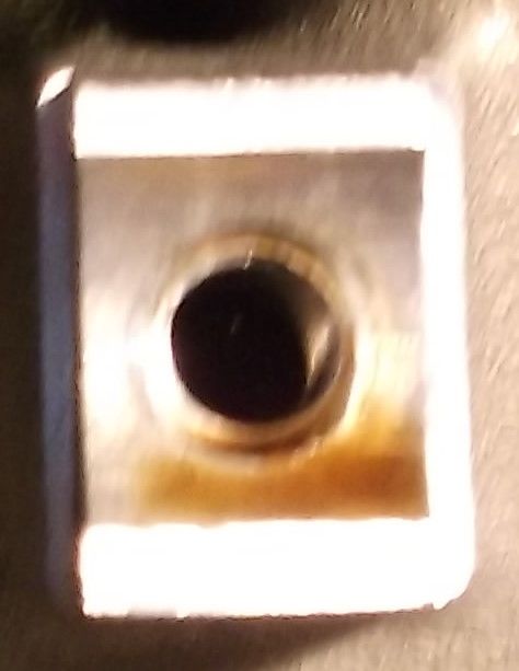
However, I did note that it is possible to tighten the rockers down 'crooked'. I have photos posted by others (on other sites) to this effect too (a crookedly installed rocker from the factory). Given that, I would think that the trunnion is not fully seating in the pedestal's cradle (the clearance therein allowing a bit of radial twist, such as in KLJ's illustration A or your drawing "Better Kinematics").
More info on other items to follow...
Last edited by Mark2009; 12-02-2012 at 06:58 PM. Reason: added photo update
12-02-2012, 04:06 PM
#903
Today I used a Comp Cams adjustable pushrod to measure zero preload. The length came out to be 7.698". Subtracting that from the OEM pushrod length, we get a directly measured preload of 0.123" (8" dial caliper). At least on my engine.
12-02-2012, 04:19 PM
#904
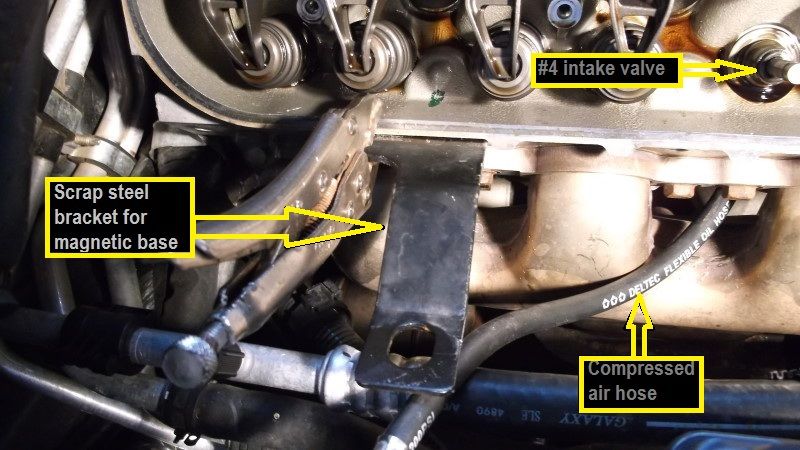
#4 exh valve: 0.022 wiggle near top of valve guide, = 0.011 guide clearance (according to our understanding of this method). Valve wiggled while held slightly off seat, maybe 0.050 off seat (when fully seated wiggle was much less).
Validation of measurement procedure:
#4 int valve: 0.005 wiggle near top of valve guide, = 0.0025 guide clearance.

There was no need to check any others.
Some items of note:
1. The springs/retainers were kinda stuck on the valve locks. After compressing the spring I had to use a bit of force to dislodge the retainer from the locks (so that the locks could be removed).
2. At TDC, the valves will not fall inside the cylinder. After roughly a 1" drop they rest on top of the piston (however, compressed air is still needed to remove and reinstall the springs).
12-02-2012, 04:23 PM
#905


Be interesting to see how close you are when you pull the heads.
12-02-2012, 05:06 PM
#906
Melting Slicks


I did the ones I removed rockers on without removing the springs. Felt solid. (I did see one post where they were able to move the stem around with spring installed) Guides on that one were junk.
I also took 1 3/4 turns to seat rocker on pedestal.
I will probably wait until a few months before warranty runs out and have heads inspected. If there are problems, I will get new aftermarket heads.
Thanks for your input John.
I also took 1 3/4 turns to seat rocker on pedestal.
I will probably wait until a few months before warranty runs out and have heads inspected. If there are problems, I will get new aftermarket heads.
Thanks for your input John.
12-02-2012, 05:41 PM
#907
Melting Slicks


http://forums.corvetteforum.com/c6-z...ts-inside.html
12-02-2012, 06:16 PM
#908
I don't have any faith in the spring-on wiggle check. Mine were tight. They were even fairly tight with the spring off but the valve pressed against the seat. Moving the valve just slightly off the seat, however, and it was wiggle city.
12-02-2012, 06:18 PM
#909
Burning Brakes

Thread Starter

I like your illustration. It's easier to understand than what I drew. My case and mistermog's case are both B. The clearance you've indicated in blue is about 0.052"...yes, really 52 mils in his and my heads. The aluminum that's transferred to the trunions goes from the bottom of the blue on the left to the bottom of the blue on the right following the arc in the B case. The illustration that I posted is to scale, 5:1. I'll add that note to it.
John
12-02-2012, 06:24 PM
#910
Burning Brakes
Thread Starter
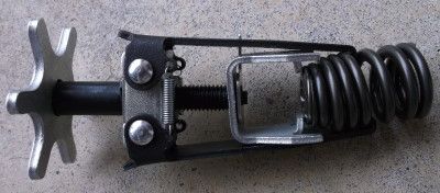
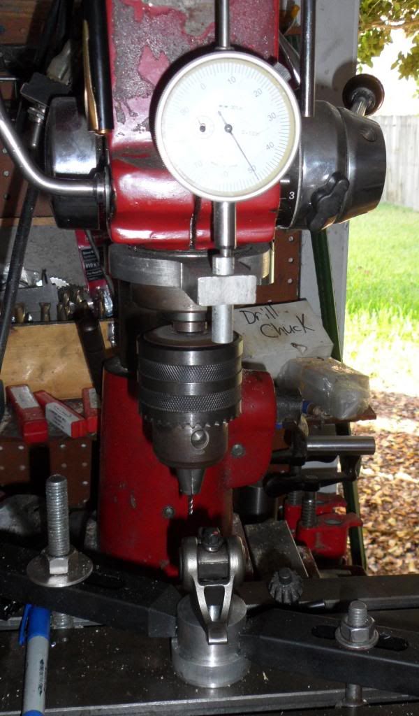
I made this pedestal to allow me to inspect rocker trunions (trunions are the heart of the rocker with the rocker shafts as an integral feature). I modified a rocker bolt as well to get access to the underside of the trunion.
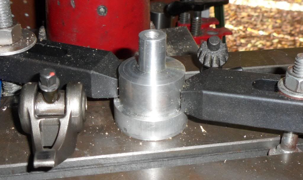
Then I installed six different rockers and measured the ditance down to the bottom side of the trunion and the feature that is 0.192" lower in the photo. I stopped after 6 because all of the data was repeating within +/-0.001"
This is what really bugs me. This is drawn to scale at 5:1. The gap between the two flats that I point to on the left is 0.052"
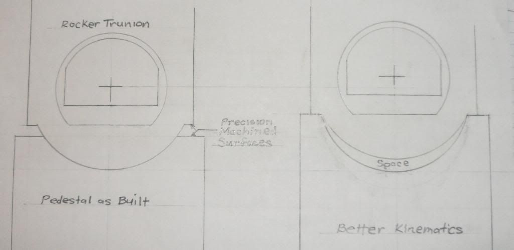
Just to be clear about what I was measuring...In my setup the rocker is upside down. So I was measuring the the vertical distance from the very bottom of the trunion to the precision machined feature that I point to on the trunion in the illustration. The surface of the pedestal that I'm pointing to is also precision machined...I'm guessing a surface finish around 0.000032" RMS. Why did GM put these precision feature on these and then not use them? The radii in the trunion and pedestal are clearly not finely machined, but these are the mating surfaces in the as built condition.
The kinematics in the as built condition go to hell quickly as soon as the two mating radii differ by a couple mils. If the trunion radius is smaller you get line contact at the bottom cutout in the pedestal and with relatively low lateral forces the trunion will "roll around" imparting bending loads on the rocker bolt and adding to its tensile stress.
If the radius in the pedestal is smaller you'll get two line contacts at the top of the pedestal. Torquing the rocker bolt generates side forces that spread the "ears" of the pedestal. This is a very sensitive interface. Are these the scenarios that GM has planned for?
On the right I have illustrated what I believe are better kinematics. I've exaggerated the space for emphasis. In the better kinematics version, precision flats mate with precision flats. Make a 0.010" mistake on either or both of these flat locations and the parts still mate with good kinematics. When your not dealing with a turned parts precision rounds are a little tricky. Precision flats are quite simple. I tend to believe that this is how some designer intended for these parts to interface.
While mistermog was over, we measured these feature inside his head as well. His dimensions were spot on with the ones in my heads. So were his bad witness marks.
The score is starting to get a little lopsided:
Good: 8
Bad: 11
John
Then I installed six different rockers and measured the ditance down to the bottom side of the trunion and the feature that is 0.192" lower in the photo. I stopped after 6 because all of the data was repeating within +/-0.001"
This is what really bugs me. This is drawn to scale at 5:1. The gap between the two flats that I point to on the left is 0.052"
Just to be clear about what I was measuring...In my setup the rocker is upside down. So I was measuring the the vertical distance from the very bottom of the trunion to the precision machined feature that I point to on the trunion in the illustration. The surface of the pedestal that I'm pointing to is also precision machined...I'm guessing a surface finish around 0.000032" RMS. Why did GM put these precision feature on these and then not use them? The radii in the trunion and pedestal are clearly not finely machined, but these are the mating surfaces in the as built condition.
The kinematics in the as built condition go to hell quickly as soon as the two mating radii differ by a couple mils. If the trunion radius is smaller you get line contact at the bottom cutout in the pedestal and with relatively low lateral forces the trunion will "roll around" imparting bending loads on the rocker bolt and adding to its tensile stress.
If the radius in the pedestal is smaller you'll get two line contacts at the top of the pedestal. Torquing the rocker bolt generates side forces that spread the "ears" of the pedestal. This is a very sensitive interface. Are these the scenarios that GM has planned for?
On the right I have illustrated what I believe are better kinematics. I've exaggerated the space for emphasis. In the better kinematics version, precision flats mate with precision flats. Make a 0.010" mistake on either or both of these flat locations and the parts still mate with good kinematics. When your not dealing with a turned parts precision rounds are a little tricky. Precision flats are quite simple. I tend to believe that this is how some designer intended for these parts to interface.
While mistermog was over, we measured these feature inside his head as well. His dimensions were spot on with the ones in my heads. So were his bad witness marks.
The score is starting to get a little lopsided:
Good: 8
Bad: 11
John John
12-02-2012, 06:33 PM
#911
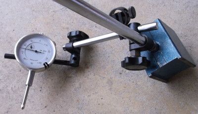
Note that style of dial indicator is far from ideal for this measurement, since the top of the valve guide is below the edge of the head's valve cover mounting rail/pad/surface. This makes it very difficult to get the tip of the dial indicator low enough on the valve (I wound up with a bit of down angle).
An older dial indicator I used to have, which I could not find today, would be much better for getting down to the proper measuring point:
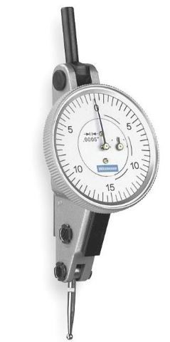
The contact point moves front and back, instead of in and out of the bottom of the dial. This lets you get the contact point down into recessed areas.
An older dial indicator I used to have, which I could not find today, would be much better for getting down to the proper measuring point:
The contact point moves front and back, instead of in and out of the bottom of the dial. This lets you get the contact point down into recessed areas.
12-02-2012, 06:38 PM
#912
Burning Brakes
Thread Starter
Note that style of dial indicator is far from ideal for this measurement, since the top of the valve guide is below the edge of the head's valve cover mounting rail/pad/surface. This makes it very difficult to get the tip of the dial indicator low enough on the valve (I wound up with a bit of down angle).
An older dial indicator I used to have, which I could not find today, would be much better for getting down to the proper measuring point:
The contact point moves front and back, instead of in and out of the bottom of the dial. This lets you get the contact point down into recessed areas.
An older dial indicator I used to have, which I could not find today, would be much better for getting down to the proper measuring point:
The contact point moves front and back, instead of in and out of the bottom of the dial. This lets you get the contact point down into recessed areas.
I made a mistake on the score. I counted Quick as Good twice.
As of the moment, it's:
Good: 7
Bad: 11
The guide issue must be far more common than anyone thought previously.
John
12-02-2012, 06:49 PM
#913
Are they affected at all by GM's design here or do they use a system that makes any errors in the GM pedestal design/execution moot?
12-02-2012, 06:55 PM
#914
Team Owner


Would love to see someone conduct these similar tests on aftermarket castings (i.e. Brodix, PRC, etc.) to compare the inherent geometry characteristics.
12-02-2012, 07:03 PM
#915
Safety Car


 12-02-2012, 07:12 PM
#916
Burning Brakes
Thread Starter
I did not inspect mine closely but no transfer leaped out at me; nor did the cradles/pedestals themselves look discolored. Unfortunately I've already buttoned mine back up so can't check any further. 2009 model year with a build date of 9/23/2008.
Update: Upon review I see that I got one photo of an unmounted pedestal. #4 intake (lower discoloration is oil) (cropped but full resolution):
However, I did note that it is possible to tighten the rockers down 'crooked'. I have photos posted by others (on other sites) to this effect too (a crookedly installed rocker from the factory). Given that, I would think that the trunnion is not fully seating in the pedestal's cradle (the clearance therein allowing a bit of radial twist, such as in KLJ's illustration A or your drawing "Better Kinematics").
More info on other items to follow...
John
12-02-2012, 07:20 PM
#917
Burning Brakes
Thread Starter
Thats my car posted above. More pics for you to diagnose Dr. John, haha!!
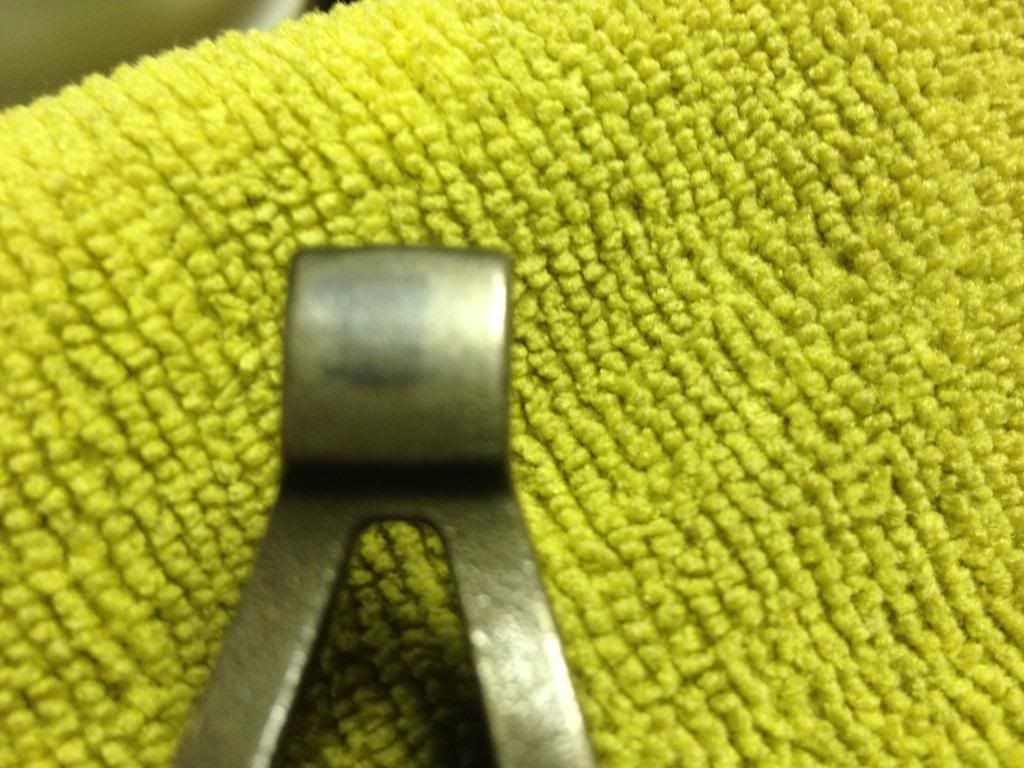

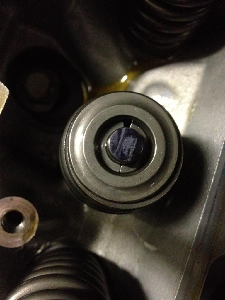
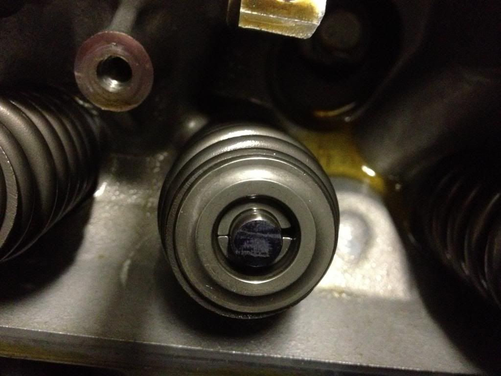
I have more pics if need be. It is an 06' w/ 30k miles. I took it apart, sharpied the end, reassembled and then turned the engine over 6 or so times. Let me know what you think. I'm thinking of going to RR's just for added piece of mind.
I have more pics if need be. It is an 06' w/ 30k miles. I took it apart, sharpied the end, reassembled and then turned the engine over 6 or so times. Let me know what you think. I'm thinking of going to RR's just for added piece of mind.
Everything looks great...best I've seen.
John
12-02-2012, 07:56 PM
#918
Drifting

Member Since: Aug 2009
Location: Colorado Springs Colorado
Posts: 1,266
Likes: 0
Received 5 Likes
on
5 Posts

50K. And you win the bet...
#4 exh valve: 0.022 wiggle near top of valve guide, = 0.011 guide clearance (according to our understanding of this method). Valve wiggled while held slightly off seat, maybe 0.050 off seat (when fully seated wiggle was much less).
Validation of measurement procedure:
#4 int valve: 0.005 wiggle near top of valve guide, = 0.0025 guide clearance.
There was no need to check any others.
Some items of note:
1. The springs/retainers were kinda stuck on the valve locks. After compressing the spring I had to use a bit of force to dislodge the retainer from the locks (so that the locks could be removed).
2. At TDC, the valves will not fall inside the cylinder. After roughly a 1" drop they rest on top of the piston (however, compressed air is still needed to remove and reinstall the springs).
12-02-2012, 08:21 PM
#919
Racer


Member Since: Mar 2007
Location: smithtown ny
Posts: 371
Likes: 0
Received 0 Likes
on
0 Posts
12-02-2012, 08:42 PM
#920
Mark and John, for simplicity wouldn't it be a valid wiggle test to just use the spring compressor to take the load off the valve, don't remove the retainers, just compress the spring, thereby allowing the valve to drop slightly into the cylinder and see if it has wiggle in it?
But for the average Joe who may not have done something like this before (I hadn't), you need to take the measurement to really know what you're 'looking' at. Plus you can inspect for any gross valve seal damage (of course the spark plugs would probably be wet if that were the case).
.
Last edited by Mark2009; 12-02-2012 at 08:51 PM. Reason: edited for brevity