
LS2 PCV System Diagram/Photo Needed
 07-31-2007, 01:37 AM
#1
Advanced

Thread Starter

I have been unable to find a good diagram or picture showing the components which make up the LS2 positive crankcase ventilation system on, for example, the 2006 Corvette. I understand that there is a short u-shaped tube (p/n 12594779) running from the valley cover port to the intake manifold port. I do not understand where tube (p/n 12571634) connects. I would like to understand the parts needed to connect to the port on the passenger side valve cover, the port on the driver's side valve cover, the other port at the front of the intake manifold, and the location of the pcv valve. Any help will be greatly appreciated.
Last edited by RennfahrerX; 07-31-2007 at 01:43 AM. Reason: to correct mistake
 07-31-2007, 02:24 AM
#2
Drifting

Member Since: Jul 2005
Location: az
Posts: 1,533
Likes: 0
Received 0 Likes
on
0 Posts
I have been unable to find a good diagram or picture showing the components which make up the LS2 positive crankcase ventilation system on, for example, the 2006 Corvette. I understand that there is a short u-shaped tube (p/n 12594779) running from the valley cover port to the intake manifold port. I do not understand where tube (p/n 12571634) connects. I would like to understand the parts needed to connect to the port on the passenger side valve cover, the port on the driver's side valve cover, the other port at the front of the intake manifold, and the location of the pcv valve. Any help will be greatly appreciated.
 07-31-2007, 09:06 AM
#3

I didn't look up the part number, but the other tube connects between the passenger side valve cover and a doohickey on the front of the head. It looks like a soleniod of some sorts and if I wasn't lazy I'd find the actual answer for you. There is a powered soleniod between the tube on the pass rocker cover and the intake bellows.
07-31-2007, 10:48 AM
#4
Advanced
Thread Starter
Thanks to both of you for your responses. I don't have a C6 (yet) and currently drive an '01 Z06 with a 427 dry sump. I'm asking this engine because I'm building a few 452 cu. in. engines for mid-60s Corvettes which will have the C6 computer and Speartech wiring harness. The engines have all C6 sensors and I want them to have the C6 PCV system as well.
07-31-2007, 11:20 AM
#5
Drifting
Member Since: Jul 2005
Location: az
Posts: 1,533
Likes: 0
Received 0 Likes
on
0 Posts
i will be working on a new catch can set up tomorrow. if someone doesn't post a picture by them, i will post one without the fuel rail cover. it will be obvious to you there is only one hose that connects from the passager valve cover to that rubber piece that is in between maf & tb for the 06 &o7. there is no "powered soleniod between the tube on the pass rocker cover and the intake bellows." i believe aintqik may have been confused with the soleniod for the fuel vapor system / EV. unless that is the 2nd part# that you provided, which in this case would have nothing to do with the pcv system
 07-31-2007, 11:39 AM
#7
Crap, you know what that may be right. I just did the air/oil seperator on mine and I remember questioning whether or not that line needed to be in the filter. On the pass rocker cover, there is a 3 inch rubber hose that attaches to a plastic hose and that goes someplace. I could swear on my 05 it provided vacuum to that soleniod but cbr is making me have doubts. I'll check it out in a few hours.
07-31-2007, 01:22 PM
#8
Advanced
Thread Starter
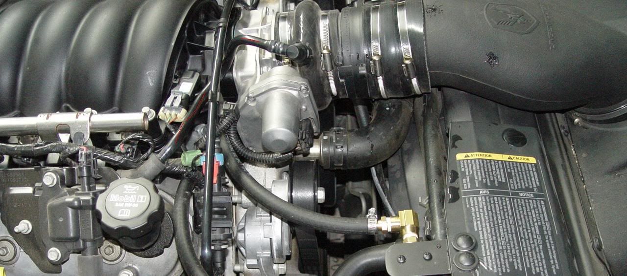
Thanks for posting the picture - that's exactly what I was looking for. The short u-tube connects the valley cover to the intake manifold and the tube in your picture connects the valve cover to the inlet as shown. Inlet air enters the crankcase through the valve cover and "dirty", or oily, air passes through the u-tube from the valley cover to the intake manifold. Your assistance is appreciated!
Doug
Doug
The following users liked this post:
Travis66 (01-21-2020)
07-31-2007, 01:25 PM
#9
Drifting
Member Since: Jul 2005
Location: az
Posts: 1,533
Likes: 0
Received 0 Likes
on
0 Posts
Thanks for posting the picture - that's exactly what I was looking for. The short u-tube connects the valley cover to the intake manifold and the tube in your picture connects the valve cover to the inlet as shown. Inlet air enters the crankcase through the valve cover and "dirty", or oily, air passes through the u-tube from the valley cover to the intake manifold. Your assistance is appreciated!
Doug
Doug
 07-31-2007, 02:20 PM
#10
Race Director


I think the picture used before is from my catch can installation. The PCV is in the valley cover, it's not a one way valve, just a sized oriface. The line from the PCV goes to just after the throttle body. The line from the passenger valve cover is just a line from the valve cover to before the throttle body. There are no solenoids or one way valves involved, just the tubes as shown.
07-31-2007, 03:34 PM
#11
Drifting
Member Since: Jul 2005
Location: az
Posts: 1,533
Likes: 0
Received 0 Likes
on
0 Posts
I think the picture used before is from my catch can installation. The PCV is in the valley cover, it's not a one way valve, just a sized oriface. The line from the PCV goes to just after the throttle body. The line from the passenger valve cover is just a line from the valve cover to before the throttle body. There are no solenoids or one way valves involved, just the tubes as shown.


 08-02-2007, 03:12 PM
#14
Burning Brakes


Thanks for posting the picture - that's exactly what I was looking for. The short u-tube connects the valley cover to the intake manifold and the tube in your picture connects the valve cover to the inlet as shown. Inlet air enters the crankcase through the valve cover and "dirty", or oily, air passes through the u-tube from the valley cover to the intake manifold. Your assistance is appreciated!
Doug
Doug
You can cap all but the valve cover vent with an open element and not hurt the motor. Really simplifies the plumbing!
03-07-2010, 03:14 PM
#15

From the dead sorry...but the hose from the pass. valve cover the the intake tube ( after the metered air) is that p/n 12571634 ?? And when routing the catch can it just goes from the valley cover tube to catch can the pass. side tube on the intake manifold...correct??? Thanks
04-17-2013, 09:09 PM
#16
Instructor
Aloha gang.
Car is an 06 z51. 43,000 miles. Should I plug all the hose connections and just put a breather in place of the oil cap? That's how I did my c5. Or should I put a breather on the driver side rear valve cover also. There's already a plug on that one.
Thanks.
Car is an 06 z51. 43,000 miles. Should I plug all the hose connections and just put a breather in place of the oil cap? That's how I did my c5. Or should I put a breather on the driver side rear valve cover also. There's already a plug on that one.
Thanks.
06-28-2018, 03:38 PM
#17
Le Mans Master


Sorry to resurrect this old thread. I just bought that plastic pcv hose and also the bellows hose from the dealer. There is no tube to connect the two. What am I missing?
Last edited by mcm95403; 06-28-2018 at 03:39 PM.
06-28-2018, 03:56 PM
#18

Hence there is a dirty side of the system, which is the valley cover port that has a small tube that connects that to the intake port right behind the TB,
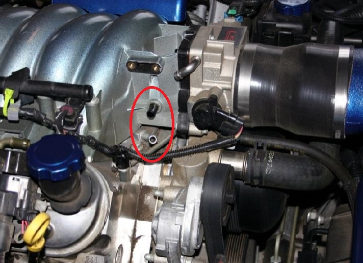
Then you have the clean side of the system, with is the port from the valve cover(s), that connects to the port in front of the TB as show in the red line drawing.
Note, if you have a dry sump motor, then the clean side is the line from the front port on the tank, to the port in front of the TB instead.
If someone changed out the accorrdion hose that connects to the front of the TB, may not have installed the port piece for the end of clean side from the vavles, or may have a model that the port is part is part of the TB instead. Hence i the photo I posted, the silver bent piece on the TB, is the clean side port on the air filter side isntead.
06-28-2018, 10:16 PM
#19
Le Mans Master
What year/motor, and dry or went sump motor?.
Hence there is a dirty side of the system, which is the valley cover port that has a small tube that connects that to the intake port right behind the TB,
Then you have the clean side of the system, with is the port from the valve cover(s), that connects to the port in front of the TB as show in the red line drawing.
Note, if you have a dry sump motor, then the clean side is the line from the front port on the tank, to the port in front of the TB instead.
If someone changed out the accorrdion hose that connects to the front of the TB, may not have installed the port piece for the end of clean side from the vavles, or may have a model that the port is part is part of the TB instead. Hence i the photo I posted, the silver bent piece on the TB, is the clean side port on the air filter side isntead.
06-29-2018, 08:25 PM
#20
Part 700 is the line/tube.
https://www.wholesalegmpartsonline.c...archString=pcv
As for accordion connector port piece, don't know if GM sells it alone, but would check with some of the after market vendors for that piece, since some of the after market intake pipes come with it already installed when you buy the part, isntead of reusing the port from the old hose (hence they must have a source for the port part piece).

Worse case, you can buy the entire accordion duct piece with port and clamps, part gm 10334217 for around $26 if you can find one in stock, and it will come with the needed port.

Short of that, if need you spec's to just lathe on up of some Delrin round stock, can give them if needed.
https://www.wholesalegmpartsonline.c...archString=pcv
As for accordion connector port piece, don't know if GM sells it alone, but would check with some of the after market vendors for that piece, since some of the after market intake pipes come with it already installed when you buy the part, isntead of reusing the port from the old hose (hence they must have a source for the port part piece).
Worse case, you can buy the entire accordion duct piece with port and clamps, part gm 10334217 for around $26 if you can find one in stock, and it will come with the needed port.
Short of that, if need you spec's to just lathe on up of some Delrin round stock, can give them if needed.

