Proper crankcase evacuation for Turbo and Centri builds
 03-26-2016, 08:52 PM
#101
Race Director

Pro Mechanic
Member Since: Mar 2004
Location: Fort Wayne IN
Posts: 12,244
Received 813 Likes
on
431 Posts
C5 of Year Finalist (performance mods) 2019
2017 C5 of the Year Finalist
2016 C5 of the Year Finalist
2015 C5 of the Year Finalist
I Believe In The Beer Fairy

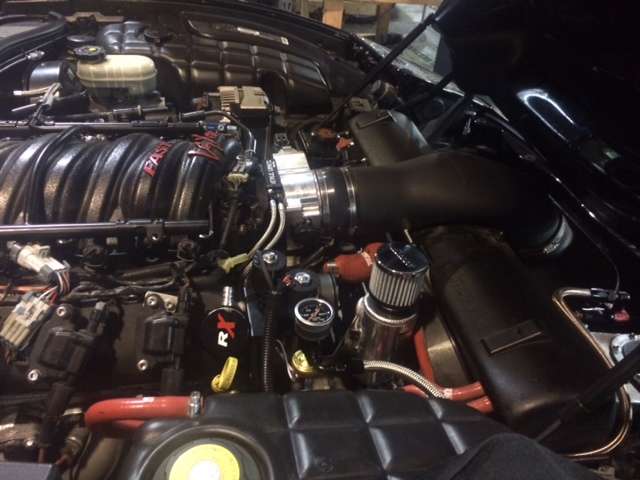
Question. Been reading this and racking my brain because of the oil smoke belching issue I have on my car coming off a high RPM/Boost pull.
Current setup is PCV as stock, and breather hoses on both rear ports on the valve covers (99 model year vc's).
Obviously not the best, especially at 16ish lbs of boost.
The PROBLEM........there are no inlets, the turbo's have filters directly on them. So I don't see a way to address a full time evac capability. Any thoughts to this? I'm probably going to move to a vented breather tank and route the PCV through a catch can as a band-aid, but that's exactly what it is. Thought I'd query some more proficient minds on this.
 03-26-2016, 11:36 PM
#102


Question. Been reading this and racking my brain because of the oil smoke belching issue I have on my car coming off a high RPM/Boost pull.
Current setup is PCV as stock, and breather hoses on both rear ports on the valve covers (99 model year vc's).
Obviously not the best, especially at 16ish lbs of boost.
The PROBLEM........there are no inlets, the turbo's have filters directly on them. So I don't see a way to address a full time evac capability. Any thoughts to this? I'm probably going to move to a vented breather tank and route the PCV through a catch can as a band-aid, but that's exactly what it is. Thought I'd query some more proficient minds on this.
Current setup is PCV as stock, and breather hoses on both rear ports on the valve covers (99 model year vc's).
Obviously not the best, especially at 16ish lbs of boost.
The PROBLEM........there are no inlets, the turbo's have filters directly on them. So I don't see a way to address a full time evac capability. Any thoughts to this? I'm probably going to move to a vented breather tank and route the PCV through a catch can as a band-aid, but that's exactly what it is. Thought I'd query some more proficient minds on this.
03-27-2016, 03:38 AM
#103
Race Director
Pro Mechanic
Member Since: Mar 2004
Location: Fort Wayne IN
Posts: 12,244
Received 813 Likes
on
431 Posts
C5 of Year Finalist (performance mods) 2019
2017 C5 of the Year Finalist
2016 C5 of the Year Finalist
2015 C5 of the Year Finalist
I Believe In The Beer Fairy
These are LG turbo's. And the problem is ONLY under a hard snap shut of the throttle after a high boost run. I can run it up to 12-14 PSI and it's clean as a whistle. Over that and it's a big belch when I shut the throttle.
03-27-2016, 02:43 PM
#104
Intermediate


Member Since: Feb 2016
Posts: 26
Likes: 0
Received 0 Likes
on
0 Posts
I am doing a 408 stroker twin turbo build at the moment and wonder if I should have one of these systems installed? It's a 03z with a UPP twin turbo kit. Any info would be appreciated
03-28-2016, 10:29 PM
#105
03-29-2016, 01:48 AM
#106
Race Director
Pro Mechanic
Member Since: Mar 2004
Location: Fort Wayne IN
Posts: 12,244
Received 813 Likes
on
431 Posts
C5 of Year Finalist (performance mods) 2019
2017 C5 of the Year Finalist
2016 C5 of the Year Finalist
2015 C5 of the Year Finalist
I Believe In The Beer Fairy
04-25-2016, 11:20 AM
#107
Melting Slicks

Thread Starter

The ColoradoSpeed and Elite standard E2-X for turbo and centri's are 20 oz's, and the "Monster" or "Ultra" are 40 oz's. There is no way with the rate of flow, the velocity of the flow that a separator can prevent oil drops that are separated from being pulled through unless at least 16 oz's for a NA V8 engine, and more for FI. To test this, simply install a E2-X or even a simple air compressor separator from Harbor Freight or Lowes and install it inline AFTER and catchcan your using and see quickly how well, or how poorly a can works by seeing what gets past any can.
04-26-2016, 08:01 AM
#108
Race Director
Member Since: Mar 2006
Location: Everywhere and Nowhere at all
Posts: 15,357
Received 1,679 Likes
on
1,135 Posts

My car is not FI.. It's a 414 stroker w Nitrous. I too am running an oil separator, and a large catch can. Works nicely w Zero oil in the intake, no blow by.. I'll be changing to a GZ vacuum pump soon.
04-26-2016, 11:44 AM
#109
Melting Slicks
Thread Starter
Post pics once you have the vac pump installed!! You can vent the outlet of the vac pump into that breathered tank you have.
How quick is that thing in the 1/4 mile? Impressive non FI build!!!
Last edited by COSPEED; 04-26-2016 at 11:44 AM.
04-27-2016, 08:15 AM
#110
Race Director
Member Since: Mar 2006
Location: Everywhere and Nowhere at all
Posts: 15,357
Received 1,679 Likes
on
1,135 Posts
Thanks for the kind words my friend.... I don't 1/4 mi race the car. Truth is, I suck!! I do however run it at 1/2 events. ( roll racing for approx. 1600ft). Friends of mine have told me it's an easy 10 sec car. Getting ready to re ring, bump the compression, and go to a direct port system for this next "Standing 1/2 mi event" coming up in Sept, Oct... Here is an idea of what it does in the half. The idea is to get up to 60mph out of the hole and watch the tree and when it turns green, you GO!! In essence, you are drag racing from a roll. So first one to flags wins... Here are two examples. Recently won "B" class ( 160mph) in a Runway rivalry event.

Probably pretty boring for you drag racers... But I like it. Plus its much easier on parts. I'll post pics once Vacum pump is installed.
Probably pretty boring for you drag racers...
But I like it. Plus its much easier on parts. I'll post pics once Vacum pump is installed.Vacuum pump is by far the best solution, just be aware that they don't last long on the street as the parts will wear. They do well in racing, but each pump can be rebuilt as needed if you stay on top of the wear of the vanes, seals, etc.
Post pics once you have the vac pump installed!! You can vent the outlet of the vac pump into that breathered tank you have.
How quick is that thing in the 1/4 mile? Impressive non FI build!!!
Post pics once you have the vac pump installed!! You can vent the outlet of the vac pump into that breathered tank you have.
How quick is that thing in the 1/4 mile? Impressive non FI build!!!
04-27-2016, 11:17 AM
#111
Melting Slicks
Thread Starter
Love this! I would agree, easy 10 sec car with driver that can launch and shift (I can't!!) effectively. Very impressive runs and if 1/2 mile racing is your passion that's still a sport!
Here is a C5 with a all NA 422 stroker that runs 10.70's all day long with 1.40 60's...but it is geared so I doubt it would be good in a 1/2 mile range (4.11's I believe):
Slow-mo video shows how it launches.

Here is a C5 with a all NA 422 stroker that runs 10.70's all day long with 1.40 60's...but it is geared so I doubt it would be good in a 1/2 mile range (4.11's I believe):
04-27-2016, 06:55 PM
#112
Race Director
Member Since: Mar 2006
Location: Everywhere and Nowhere at all
Posts: 15,357
Received 1,679 Likes
on
1,135 Posts
Man, that's good stuff... That would be fun... I do have an fbod that I could take to the track though... little G5X2 cam with a Yank SS3600 stall, headers, and some bolt on's.... lol
04-28-2016, 02:11 PM
#113
Melting Slicks
Thread Starter
That will 1/4 mile!!!
04-28-2016, 02:12 PM
#114
Melting Slicks
Thread Starter
Question. Been reading this and racking my brain because of the oil smoke belching issue I have on my car coming off a high RPM/Boost pull.
Current setup is PCV as stock, and breather hoses on both rear ports on the valve covers (99 model year vc's).
Obviously not the best, especially at 16ish lbs of boost.
The PROBLEM........there are no inlets, the turbo's have filters directly on them. So I don't see a way to address a full time evac capability. Any thoughts to this? I'm probably going to move to a vented breather tank and route the PCV through a catch can as a band-aid, but that's exactly what it is. Thought I'd query some more proficient minds on this.
Current setup is PCV as stock, and breather hoses on both rear ports on the valve covers (99 model year vc's).
Obviously not the best, especially at 16ish lbs of boost.
The PROBLEM........there are no inlets, the turbo's have filters directly on them. So I don't see a way to address a full time evac capability. Any thoughts to this? I'm probably going to move to a vented breather tank and route the PCV through a catch can as a band-aid, but that's exactly what it is. Thought I'd query some more proficient minds on this.
There is a new turbo venturi valve that will take a small part of the boost and create up to 12-16" of vacuum during full boost that will work for you.
07-31-2016, 01:53 PM
#115

Valley cover port is the primary PCV dirty side outlet from the crankcase. That would run to the center of the air/oil separator. I prefer the rear of the drivers side valve cover for LS engines as the fresh incoming air is entering the passenger side valve cover and I like a full complete flushing of the crankcase. If you only draw foul vapors from the valley on a LS engine, the drivers side valve train will be stagnant and water and sulfuric acid condense under the valve cover and allow corrosion of the rocker arms and the retaining caps for the needle bearings as well as springs, etc.
With a LT1, then use the valley as they have a more robust baffle underneath than the LS engines, and fresh air enters both valve covers so no stagnant areas remain.
One outlet from the main separator will have an inline checkvalve in it that runs to the intake manifold and uses the vacuum suction to evacuate when not in boost, and that valve will close when vacuum drops and boost is present so no pressure can enter the crankcase, and the second outlet with checkvalve opens and uses the suction present at the centri blowers inlet to always maintain evacuation suction on the crankcase. This prevents pressure issues and provides a more stable piston ring seal as well as always is evacuating the damaging compound and oil laden vapors out of the crankcase before they have a chance to fall and mix with the engine oil. So, deals with crankcase pressure, stops oil ingestion, and keeps oil cleaner as well as better ring seal for power and less wear.
Let me know if your following it all.
Thanks
08-01-2016, 01:15 PM
#116
Melting Slicks
Thread Starter
Hi Ron,
This is NOT acceptable. This is a very common misconception with most "tuner shops" today. If you defeat the actual evacuation functions of the PCV system, then you are leaving all of the unburnt fuel and damaging combustion by-products in the crankcase to mix with the engine oil. It also allows crankcase pressure be always present, which is never a good thing. Todays engines all come with a "low tension" piston ring set to reduce friction and improve fuel economy, it is critical that the crankcase ALWAYS have suction present as the rings can only remain stable and seal properly if there is "pressure above, suction below" the rings, or ring flutter occurs and not only does this increase blow-by, it also wears the edges of the rings, the piston ringlands, and the cylinder walls them selves over time. So they have sacrificed engine life to only "vent" pressure. The symptoms generally will not show for 20-40k miles, but by then most of the engine internal parts will have excessive wear.
Here is an excellent article for you and them to read on this:
http://www.dragzine.com/tech-stories...en-horsepower/
Outside of the Professional racing industry there are few that actually understand all that is involved with proper crankcase evacuation, and NO professional race teams "vent" pressure, they all run belt driven vacuum pumps to always be pulling suction and the contaminates from the crankcase before they can settle and mix with the engine oil, as once mixed, they are there to stay.
Education on these subjects is hard to find, as no automotive tech schools or dealer training programs teach any of this now, and have not for decades.
The E2-X and E2 systems, if used with both checkvalves will always pull evacuation on the crankcase and the Ultra system will handle over 1000 WHP properly.
Here is what the shop should follow as for diagrams of all involved with turbo or centrifugal super charging:

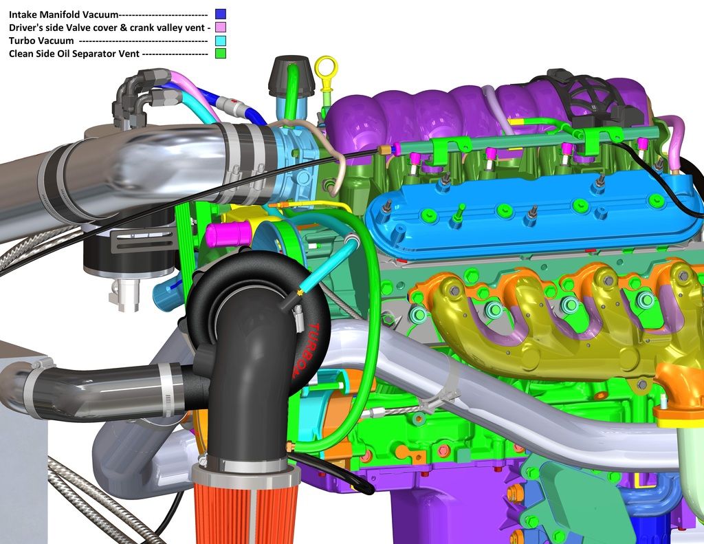
So all understand,
The E2, E2-X, and E2-Ultra all use 2 separate evacuation suction sources. While in non-boost operation, the intake manifold vacuum provides evacuation suction with the cleanside separator providing filtered fresh make up air that replaces the foul/dirty contaminate laden vapors being removed from the opposite valve cover as the filtered fresh air is entering.
When the engine begins to transition into boost, the primary checkvalve will close as pressure is detected int he intake manifold, and the secondary valve will open using the vacuum/suction present at the head units inlet to continue pulling suction at all times on the crankcase. The main separator (catchcan) traps 95% plus of all the oil mist and other contaminates (water, unburnt fuel, abrasive soot/carbon & Ash) from the crankcase vapors so only scrubbed vapors enter the intake air charge. The billet cleanside separator will trap any oil mist present during any brief periods of pressure as the checkvalves switch, etc. so you have addressed all paths of ingestion while maintaining a emissions compliant "closed system" legal for street use.
Again, your shop is probably a great shop of skilled techs, but if no one ever trained them on all that is involved in proper crankcase evacuation and PCV system function, they will only think of the most obvious, and that is pressure. And to vent it allows it to ALWAYS be present as simple flow dynamics dictates pressure must always be greater behind any vent than can be forced out a breather or vent. And there is nothing good about pressure EVER being present in the crankcase as all breather or vented solutions allow.
We here at Elite Engineering are more than happy to offer training to any shop wishing to learn this seldom taught subject, but do NOT run your car as they configured it.
Let us know if we can be of more assistance.
Thanks,
This is NOT acceptable. This is a very common misconception with most "tuner shops" today. If you defeat the actual evacuation functions of the PCV system, then you are leaving all of the unburnt fuel and damaging combustion by-products in the crankcase to mix with the engine oil. It also allows crankcase pressure be always present, which is never a good thing. Todays engines all come with a "low tension" piston ring set to reduce friction and improve fuel economy, it is critical that the crankcase ALWAYS have suction present as the rings can only remain stable and seal properly if there is "pressure above, suction below" the rings, or ring flutter occurs and not only does this increase blow-by, it also wears the edges of the rings, the piston ringlands, and the cylinder walls them selves over time. So they have sacrificed engine life to only "vent" pressure. The symptoms generally will not show for 20-40k miles, but by then most of the engine internal parts will have excessive wear.
Here is an excellent article for you and them to read on this:
http://www.dragzine.com/tech-stories...en-horsepower/
Outside of the Professional racing industry there are few that actually understand all that is involved with proper crankcase evacuation, and NO professional race teams "vent" pressure, they all run belt driven vacuum pumps to always be pulling suction and the contaminates from the crankcase before they can settle and mix with the engine oil, as once mixed, they are there to stay.
Education on these subjects is hard to find, as no automotive tech schools or dealer training programs teach any of this now, and have not for decades.
The E2-X and E2 systems, if used with both checkvalves will always pull evacuation on the crankcase and the Ultra system will handle over 1000 WHP properly.
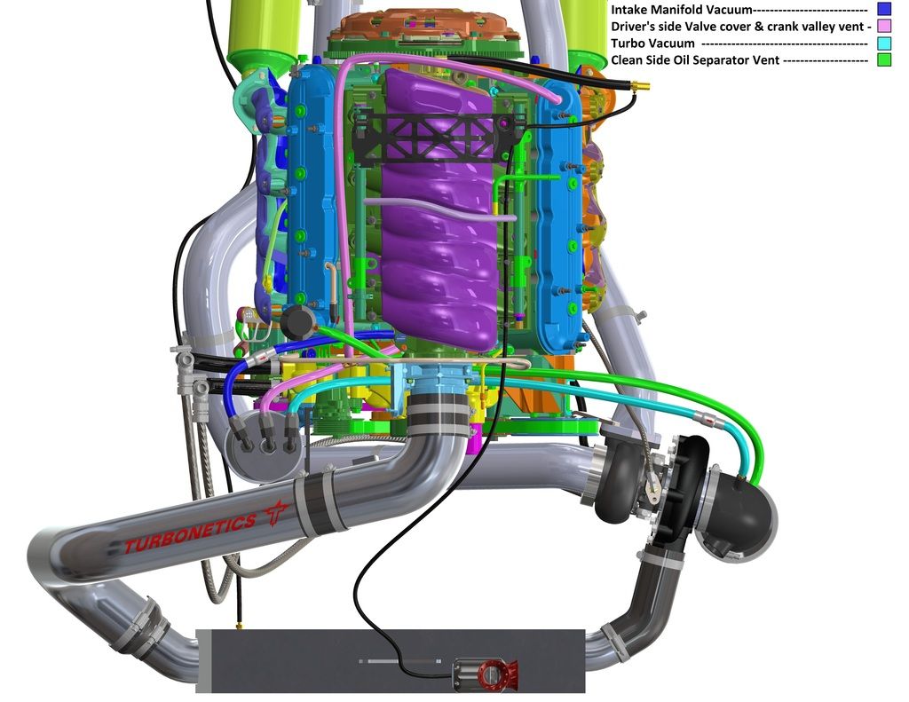
Here is what the shop should follow as for diagrams of all involved with turbo or centrifugal super charging:


So all understand,
The E2, E2-X, and E2-Ultra all use 2 separate evacuation suction sources. While in non-boost operation, the intake manifold vacuum provides evacuation suction with the cleanside separator providing filtered fresh make up air that replaces the foul/dirty contaminate laden vapors being removed from the opposite valve cover as the filtered fresh air is entering.
When the engine begins to transition into boost, the primary checkvalve will close as pressure is detected int he intake manifold, and the secondary valve will open using the vacuum/suction present at the head units inlet to continue pulling suction at all times on the crankcase. The main separator (catchcan) traps 95% plus of all the oil mist and other contaminates (water, unburnt fuel, abrasive soot/carbon & Ash) from the crankcase vapors so only scrubbed vapors enter the intake air charge. The billet cleanside separator will trap any oil mist present during any brief periods of pressure as the checkvalves switch, etc. so you have addressed all paths of ingestion while maintaining a emissions compliant "closed system" legal for street use.
Again, your shop is probably a great shop of skilled techs, but if no one ever trained them on all that is involved in proper crankcase evacuation and PCV system function, they will only think of the most obvious, and that is pressure. And to vent it allows it to ALWAYS be present as simple flow dynamics dictates pressure must always be greater behind any vent than can be forced out a breather or vent. And there is nothing good about pressure EVER being present in the crankcase as all breather or vented solutions allow.
We here at Elite Engineering are more than happy to offer training to any shop wishing to learn this seldom taught subject, but do NOT run your car as they configured it.
Let us know if we can be of more assistance.
Thanks,
08-01-2016, 05:04 PM
#117
Hi Ron,
This is NOT acceptable. This is a very common misconception with most "tuner shops" today. If you defeat the actual evacuation functions of the PCV system, then you are leaving all of the unburnt fuel and damaging combustion by-products in the crankcase to mix with the engine oil. It also allows crankcase pressure be always present, which is never a good thing. Todays engines all come with a "low tension" piston ring set to reduce friction and improve fuel economy, it is critical that the crankcase ALWAYS have suction present as the rings can only remain stable and seal properly if there is "pressure above, suction below" the rings, or ring flutter occurs and not only does this increase blow-by, it also wears the edges of the rings, the piston ringlands, and the cylinder walls them selves over time. So they have sacrificed engine life to only "vent" pressure. The symptoms generally will not show for 20-40k miles, but by then most of the engine internal parts will have excessive wear.
Here is an excellent article for you and them to read on this:
http://www.dragzine.com/tech-stories...en-horsepower/
Outside of the Professional racing industry there are few that actually understand all that is involved with proper crankcase evacuation, and NO professional race teams "vent" pressure, they all run belt driven vacuum pumps to always be pulling suction and the contaminates from the crankcase before they can settle and mix with the engine oil, as once mixed, they are there to stay.
Education on these subjects is hard to find, as no automotive tech schools or dealer training programs teach any of this now, and have not for decades.
The E2-X and E2 systems, if used with both checkvalves will always pull evacuation on the crankcase and the Ultra system will handle over 1000 WHP properly.
Here is what the shop should follow as for diagrams of all involved with turbo or centrifugal super charging:
So all understand,
The E2, E2-X, and E2-Ultra all use 2 separate evacuation suction sources. While in non-boost operation, the intake manifold vacuum provides evacuation suction with the cleanside separator providing filtered fresh make up air that replaces the foul/dirty contaminate laden vapors being removed from the opposite valve cover as the filtered fresh air is entering.
When the engine begins to transition into boost, the primary checkvalve will close as pressure is detected int he intake manifold, and the secondary valve will open using the vacuum/suction present at the head units inlet to continue pulling suction at all times on the crankcase. The main separator (catchcan) traps 95% plus of all the oil mist and other contaminates (water, unburnt fuel, abrasive soot/carbon & Ash) from the crankcase vapors so only scrubbed vapors enter the intake air charge. The billet cleanside separator will trap any oil mist present during any brief periods of pressure as the checkvalves switch, etc. so you have addressed all paths of ingestion while maintaining a emissions compliant "closed system" legal for street use.
Again, your shop is probably a great shop of skilled techs, but if no one ever trained them on all that is involved in proper crankcase evacuation and PCV system function, they will only think of the most obvious, and that is pressure. And to vent it allows it to ALWAYS be present as simple flow dynamics dictates pressure must always be greater behind any vent than can be forced out a breather or vent. And there is nothing good about pressure EVER being present in the crankcase as all breather or vented solutions allow.
We here at Elite Engineering are more than happy to offer training to any shop wishing to learn this seldom taught subject, but do NOT run your car as they configured it.
Let us know if we can be of more assistance.
Thanks,

Just to make sure I'm clear. My oil filer cap where the clean side separator would go is on the opposite side (as depicted), does this matter? If I were to set mine up like the diagram.
1) I would need to take the line that has the filter on it currently and plum it to the connection closest to the SC suction with the check valve pointing toward the connection, away from the can (open under vacuum).
2) Tie the passenger side valve cover with the valley connection (crank case) and plum that to the center connection of the catch can (currently only has the valley connection).
3) The other outside connection is correct and connected to the intake connection with the check valve pointing toward the intake.
4) Install the clean side separator on the driver side valve cover (replacing the oil fill cap) and plum that to the connection closest to the air filter.
Last edited by VAVetteC7; 08-01-2016 at 05:29 PM.
08-01-2016, 05:25 PM
#118
Melting Slicks
Thread Starter
First I want to say thanks for all the information you have put out on the forum, it's most certainly educated me at least enough to know what I was seeing wasn't right.
Just to make sure I'm clear. My oil filer cap where the clean side separator would go is on the opposite side (as depicted), does this matter? If I were to set mine up like the diagram.
1) I would need to take the line that has the filter on it currently and plum it to the connection closest to the SC suction with the check valve pointing toward the connection, away from the can (open under vacuum).
2) Tie the passenger side valve cover with the valley connection (crank case) and plum that to the center connection of the catch can (currently only has the valley connection).
3) The other outside connection is correct and connected to the intake connection with the check valve pointing toward the intake.
3) Install the clean side separator on the driver side valve cover (replacing the oil fill cap) and plum that to the connection closest to the air filter.


Hope this helps! The Elite is slightly different, but same routing.
08-01-2016, 06:27 PM
#119
Correct. The LT1 has the oil fill on the opposite side of the engine than the LS series engines. Checkvalves go on the 2 outer fittings flowing away from the can. Center is inlet from your valley cover barb. It comes out facing the driverside than the passenger side like the diagrams. Cleanside comes from the main air filter for the head unit, right into the end of the filter so it is filtered fresh air entering. These are pics of an earlier version with plastic checkvalves instead of the billet ones you should have.


Hope this helps! The Elite is slightly different, but same routing.
Hope this helps! The Elite is slightly different, but same routing.