
It just died.. Then started ??
 01-31-2013, 10:50 PM
#1
Heel & Toe

Thread Starter

Member Since: Nov 2012
Posts: 18
Likes: 0
Received 0 Likes
on
0 Posts
Coming home from work today my 02 started bucking, coughing then up and died. I pulled over waited a minute and it started right up. I managed to get to my brothers garage with no problem but it obvious there is one. I have been chasing a p1285 code for about three weeks, I've replaced the APP and the Throttle body. I've notice at higher RPM there is a miss and when I got home the car seemed to die then start up again. Is it possible for a TAC module to cut in and out? Or does it either work or not work? Anybody else ever had this happen or hear of it?
 01-31-2013, 11:57 PM
#4
Melting Slicks

Member Since: Jun 2012
Location: Oceanside California
Posts: 3,163
Likes: 0
Received 4 Likes
on
4 Posts
If this is a new issue after messing with the TB etc, disconnect them and make sure you didn't bend any prongs or cross any wires if you went that far into it.
02-01-2013, 12:06 AM
#5
Heel & Toe
Thread Starter
Member Since: Nov 2012
Posts: 18
Likes: 0
Received 0 Likes
on
0 Posts
All I did was unplug and plug back in but I'll give it a look. I honestly kept waiting for it to go into safe mode it was running so badly but it just shut off, then I restarted it and it ran... Decent ,. Idled fine but had a miss or surge at shifting rpm
02-01-2013, 09:34 AM
#7
 02-01-2013, 11:18 AM
#10
Heel & Toe
Thread Starter
Member Since: Nov 2012
Posts: 18
Likes: 0
Received 0 Likes
on
0 Posts
No.. How do you do that??
Alot of this began after changing the heads in December,.. Possibly something not right with injectors or fuel line.??
I'm at work now so I can't check till I get home. I will pull covers and chech everything.. appreciate the help..
Alot of this began after changing the heads in December,.. Possibly something not right with injectors or fuel line.??
I'm at work now so I can't check till I get home. I will pull covers and chech everything.. appreciate the help..
02-01-2013, 02:02 PM
#11
Cheap fuel pressure gauge from Sears/Autozone.
02-01-2013, 02:48 PM
#12
Tech Contributor


Member Since: Dec 1999
Location: Anthony TX
Posts: 32,736
Received 2,180 Likes
on
1,583 Posts
CI 6,7,8,9,11 Vet
St. Jude Donor '08

Hmmmmm,, So you worked on the heads. Did you properly connect Ground G-107 on the back of the drivers head?? That is the main ground for the coils and injectors and can cause your issue if it is loose or broken.
DTC P0351-P0358
Circuit Description
The ignition system on this engine uses an individual ignition control module (ICM) for each cylinder. The powertrain control module (PCM) controls the ignition system operation. The PCM controls each coil using one of 8 ignition control (IC) circuits. The PCM commands the IC circuit low if a spark event is requested. This causes the ICM to energize the ignition coil to create a spark at the spark plug. Each ICM has the following circuits:
An ignition control circuit
An Ignition 1 voltage circuit
A ground circuit
A reference low circuit
The PCM controls the sequence and the timing. This DTC sets if the IC circuit is out of range.
Conditions for Running the DTC
The engine is operating.
Conditions for Setting the DTC
The PCM detects that the ignition control circuit is experiencing one of the following conditions:
Grounded
Open
Shorted to voltage
The conditions are met for less than 1 second.
Action Taken When the DTC Sets
The control module illuminates the malfunction indicator lamp (MIL) on the second consecutive ignition cycle that the diagnostic runs and fails.
The control module records the operating conditions at the time the diagnostic fails. The first time the diagnostic fails, the control module stores this information in the Failure Records. If the diagnostic reports a failure on the second consecutive ignition cycle, the control module records the operating conditions at the time of the failure. The control module writes the operating conditions to the Freeze Frame and updates the Failure Records.
Conditions for Clearing the MIL/DTC
The control module turns OFF the malfunction indicator lamp (MIL) after 3 consecutive ignition cycles that the diagnostic runs and does not fail.
A current DTC, Last Test Failed, clears when the diagnostic runs and passes.
A history DTC clears after 40 consecutive warm-up cycles, if no failures are reported by this or any other emission related diagnostic.
Clear the MIL and the DTC with a scan tool.
Test Description
The numbers below refer to the step numbers on the diagnostic table.
This step verifies the integrity of the IC circuit, and of the PCM output.
This step tests for a short to ground on the ignition control circuit.
Step
Action
Value
Yes
No
Schematic Reference: Engine Controls Schematics
1
Did you perform the Diagnostic System Check-Engine Controls?
--
Go to Step 2
Go to Diagnostic System Check - Engine Controls
2
Observe the Freeze Frame/Failure Records for this DTC.
Turn OFF the ignition for 30 seconds.
Start the engine.
In order to operate the vehicle under the conditions which set the DTC, use the following information:
The data in the Freeze Frame/Failure Records
The parameters listed in the Conditions for Running in the DTC
Does the DTC fail this ignition?
--
Go to Step 3
Go to Intermittent Conditions
3
Turn OFF the engine.
Disconnect the respective electrical connector of the ignition coil.
Start the engine.
Connect the DMM, select the DC Hertz setting in order to measure the frequency at the respective IC signal circuit. Refer to Measuring Frequency in Wiring Systems.
Does the frequency measure within the range that is specified?
3-20 Hz
Go to Step 7
Go to Step 4
4
Measure the voltage at the respective IC signal circuit using the DMM.
Is the signal circuit voltage more than the specified value?
1 V
Go to Step 13
Go to Step 5
5
Turn OFF the ignition.
Disconnect the PCM connector. Refer to Powertrain Control Module (PCM) Replacement .
Connect the DMM in order to test the continuity from the respective ignition control circuit, at the ignition coil electrical connector, to the PCM connector. Refer to Testing for Continuity in Wiring Systems.
Does the DMM indicate continuity?
--
Go to Step 6
Go to Step 14
6
Test the respective ignition control circuit for a short to ground. Refer to Testing for Continuity in Wiring Systems.
Did you find and correct the condition?
--
Go to Step 17
Go to Step 15
7
Turn ON the ignition, with the engine OFF.
Connect a test lamp to the battery ground in order to probe the Ignition 1 voltage circuit of the IC. Refer to Troubleshooting with a Test Lamp and to Probing Electrical Connectors in Wiring Systems.
Does the test lamp illuminate?
--
Go to Step 8
Go to Step 9
8
Connect a test lamp to B+ in order to probe the ground circuit of the Ignition Coil. Refer to Troubleshooting with a Test Lamp and to Probing Electrical Connectors in Wiring Systems.
Does the test lamp illuminate?
--
Go to Step 11
Go to Step 10
9
Repair the open in the ignition 1 voltage circuit. Refer to Wiring Repairs in Wiring Systems.
Did you complete the repair?
--
Go to Step 17
--
10
Repair the open in the ground circuit for the IC. Refer to Wiring Repairs in Wiring Systems.
Did you complete the repair?
--
Go to Step 17
--
11
Inspect for poor connections at the IC harness connector. Refer to Testing for Intermittent and Poor Connections and to Connector Repairs in Wiring Systems.
Did you find and correct the condition?
--
Go to Step 17
Go to Step 12
12
Replace the ignition coil. Refer to Ignition Coil(s) Replacement .
Did you complete the replacement?
--
Go to Step 17
--
13
Repair the IC circuit for a short to voltage. Refer to Wiring Repairs in Wiring Systems.
Did you complete the repair?
--
Go to Step 17
--
14
Repair the IC circuit for an open circuit. Refer to Wiring Repairs in Wiring Systems.
Did you complete the repair?
--
Go to Step 17
--
15
Inspect for poor connections at the PCM harness connector. Refer to Testing for Intermittent and Poor Connections and to Connector Repairs in Wiring Systems.
Did you find and correct the condition?
--
Go to Step 17
Go to Step 16
16
Replace the PCM. Refer to Powertrain Control Module (PCM) Replacement .
Did you complete the replacement?
--
Go to Step 17
--
17
Use a scan tool in order to clear the DTCs.
Turn OFF the ignition for 30 seconds.
Start the engine.
Operate the vehicle within the Conditions for Running the DTC, as specified in the supporting text.
Does the DTC run and pass?
--
Go to Step 18
Go to Step 2
18
Use a scan tool in order to observe the stored information in Capture Info.
Does the scan tool display any DTCs that you have not diagnosed?
--
Go to Diagnostic Trouble Code (DTC) List
System OK
--------------------------------------------------------------------------------
Document ID# 776184
2002 Chevrolet Corvette
--------------------------------------------------------------------------------------------------------------------------------------------------------------------------------
DTC P1285
Circuit Description
The accelerator pedal position (APP) sensor is mounted on the accelerator pedal assembly. The sensor is actually 3 individual APP sensors within 1 housing. Three separate signal, low reference and 5-volt reference circuits connect the APP sensor assembly and the throttle actuator control (TAC) module. Each sensor has a unique functionality. The APP sensor 1 signal increases as the accelerator pedal is depressed, from below 1 volt at 0 percent pedal travel, with the pedal at rest, to above 2 volts at 100 percent pedal travel, with the pedal fully depressed. The APP sensor 2 signal decreases from above 4 volts at 0 percent pedal travel to below 2.9 volts at 100 percent pedal travel. The APP sensor 3 signal decreases from around 3.8 volts at 0 percent pedal travel to below 3.1 volts at 100 percent pedal travel. Notice that the signal circuits for APP sensor 2 and APP sensor 3 pull up to 5-volts and the APP sensor 1 signal circuit is referenced to low reference within the TAC module.
Conditions for Running the DTC
DTCs P0606, P1517, or P1518 are not set.
The ignition switch is in the crank or the run position.
The ignition voltage is greater than 5.23 volts.
Conditions for Setting the DTC
APP sensor 3 voltage is less than 01.63 volts or greater than 4.28 volts.
All above conditions present for less than 1 second.
Action Taken When the DTC Sets
The control module stores the DTC information into memory when the diagnostic runs and fails.
The malfunction indicator lamp (MIL) will not illuminate.
The control module records the operating conditions at the time the diagnostic fails. The control module stores this information in the Failure Records.
If one or more APP sensor DTCs are set for a single APP sensor, the following occurs:
The control module will not command Reduced Engine Power mode.
The control module will use the remaining two APP sensors to calculate throttle response.
If certain multiple APP sensor DTCs are set for more than one APP sensor, the following occurs:
The control module commands Reduced Engine Power mode.
The APP indicated angle is limited to a predetermined value to limit the amount of throttle control.
The message center displays Reduced Engine Power.
If all three APP sensors are out of range, the following occurs:
The control module commands Reduced Engine Power mode.
The APP indicated angle is limited to 0 percent. The control module only allows the engine to idle.
The message center displays Reduced Engine Power.
Conditions for Clearing the DTC
A current DTC Last Test Failed clears when the diagnostic runs and passes.
A history DTC clears after 40 consecutive warm-up cycles, if no failures are reported by this or any other non-emission related diagnostic.
Clear the DTC with a scan tool.
Diagnostic Aids
Inspect the throttle actuator control (TAC) module connectors for signs of water intrusion. When water intrusion occurs, multiple DTCs could be set with no DTC circuit or component conditions found during diagnostic testing.
When the TAC module detects throttle movement with a DTC P1285 set, a DTC P1286 also sets.
When the TAC module detects a condition within the TAC system, more than 1 TAC system related DTC may set. This is due to the many redundant tests that run continuously on this system. Locating and repairing 1 individual condition may correct more than 1 DTC. Disconnecting components during testing may set additional DTCs. Keep this in mind when reviewing the stored information, Capture info.
For an intermittent, refer to Intermittent Conditions .
Test Description
The number below refers to the step number on the diagnostic table.
When the TAC module detects a condition within the TAC system, more than 1 TAC system related DTC may set. This is due to the many redundant tests that run continuously on this system. Locating and repairing 1 individual condition may correct more than 1 DTC. Disconnecting the components during testing may set additional DTCs. Keep this in mind when reviewing the stored information, Capture info.
DTC P1285 - Accelerator Pedal Position (APP) Sensor 3 Circuit Step
Action
Values
Yes
No
Schematic Reference: Engine Controls Schematics
1
Did you perform the Diagnostic System Check-Engine Controls?
--
Go to Step 2
Go to Diagnostic System Check - Engine Controls
2
Important
If DTC P1518 or P1220 is also set, refer to Diagnostic Trouble Code (DTC) List for further diagnosis.
Turn ON the ignition, with the engine OFF.
With a scan tool, observe the APP senso 3 voltage parameter.
Does the scan tool indicate APP sensor 3 voltage within the specified values?
3.29-4.28 V
Go to Step 3
Go to Step 6
3
Fully depress the accelerator pedal to the wide open throttle (WOT) position.
Does the scan tool indicate APP sensor 3 voltage within the specified values?
1.63-3.1 V
Go to Step 4
Go to Step 6
4
Turn OFF the ignition for 15 seconds.
Turn ON the ignition, with the engine OFF.
With a scan tool, observe the diagnostic trouble code (DTC) option.
Lightly touch and move the related engine wiring harnesses and connectors for the APP sensor while monitoring the DTC info status.
Did this DTC fail this ignition during the above test?
--
Go to Step 20
Go to Step 5
5
Slowly depress the accelerator pedal to WOT. Slowly return the accelerator pedal to the released position.
Did this DTC fail this ignition during the above test?
--
Go to Step 21
Go to Diagnostic Aids
6
Disconnect the APP sensor harness connector.
With a DMM, Test the APP sensor 3 signal circuit for voltage.
Does the DMM indicate APP sensor 3 signal voltage within the specified values?
3.94-6.06 V
Go to Step 11
Go to Step 7
7
Turn OFF the ignition.
Disconnect the TAC module harness connector containing the APP Sensor circuits.
Turn ON the ignition, with the engine OFF.
With a DMM, Test the APP sensor 3 signal circuit for a short to voltage. Refer to Circuit Testing and Wiring Repairs in Wiring Systems.
Did you find and correct the condition?
--
Go to Step 25
Go to Step 8
8
With a DMM, test the APP sensor 3 signal circuit for an open or for high resistance. Refer to Circuit Testing and Wiring Repairs in Wiring Systems.
Did you find and correct the condition?
--
Go to Step 25
Go to Step 9
9
With a DMM, test the APP sensor 3 signal circuit for a short to ground. Refer to Circuit Testing and Wiring Repairs in Wiring Systems.
Did you find and correct the condition?
--
Go to Step 25
Go to Step 10
10
Disconnect the other TAC module harness connector.
With a DMM, test for a short between the APP sensor 3 signal circuit and all other TAC module circuits. Refer to Circuit Testing and Wiring Repairs in Wiring Systems.
Did you find and correct the condition?
--
Go to Step 25
Go to Step 23
11
With a DMM, test the APP sensor 3 5-volt reference circuit for voltage.
Does the DMM indicate voltage within the specified values?
3.94-6.06 V
Go to Step 16
Go to Step 12
12
Turn OFF the ignition.
Disconnect the TAC module harness connector containing the APP Sensor circuits.
Turn ON the ignition, with the engine OFF.
With a DMM, test the APP sensor 3 5-volt reference circuit for a short to voltage. Refer to Circuit Testing and Wiring Repairs in Wiring Systems.
Did you find and correct the condition?
--
Go to Step 25
Go to Step 13
13
With a DMM, test the APP sensor 3 5-volt reference circuit for an open or for high resistance. Refer to Circuit Testing and Wiring Repairs in Wiring Systems.
Did you find and correct the condition?
--
Go to Step 25
Go to Step 14
14
With a DMM, test the APP sensor 3 5-volt reference circuit for a short to ground. Refer to Circuit Testing and Wiring Repairs in Wiring Systems.
Did you find and correct the condition?
--
Go to Step 25
Go to Step 15
15
With a DMM, test for a short between the APP sensor 3 5-volt reference circuit and all other TAC module circuits. Refer to Circuit Testing and Wiring Repairs in Wiring Systems.
Did you find and correct the condition?
--
Go to Step 25
Go to Step 23
16
With a DMM connected between the APP sensor 3 low reference circuit and the APP sensor 1 low reference circuit, measure the resistance.
Does the DMM indicate resistance within the specified values?
0-5 ohms
Go to Step 18
Go to Step 17
17
Turn OFF the ignition.
Disconnect the TAC module harness connector containing the APP sensor circuits.
With a DMM, test the APP sensor 3 low reference circuit for an open or for high resistance. Refer to Circuit Testing and Wiring Repairs in Wiring Systems.
Did you find and correct the condition?
--
Go to Step 25
Go to Step 23
18
With a scan tool , observe the APP sensor 3 voltage parameter.
Connect a fused jumper between the APP sensor 3 signal circuit and the APP sensor 3 low reference circuit at the APP sensor harness connector.
Does the scan tool indicate APP sensor 3 voltage at the specified value?
0 V
Go to Step 19
Go to Step 24
19
Turn OFF the ignition.
Disconnect the TAC module harness connectors.
With a DMM, test for a short between the APP sensor 3 signal circuit and all other TAC module circuits. Refer to Circuit Testing and Wiring Repairs in Wiring Systems.
Did you find and correct the condition?
--
Go to Step 25
Go to Step 21
20
Repair the intermittent connection as necessary. Refer to Wiring Repairs in Wiring Systems.
Did you complete the repair?
--
Go to Step 25
--
21
Inspect for poor connections at the harness connector of the APP sensor. Refer to Testing for Intermittent and Poor Connections and Repairing Connector Terminals in Wiring Systems.
Did you find and correct the condition?
--
Go to Step 25
Go to Step 22
22
Replace the APP sensor assembly. Refer to Accelerator Pedal Position (APP) Sensor Replacement .
Did you complete the replacement?
--
Go to Step 25
--
23
Inspect for poor connections at the harness connector of the TAC module . Refer to Testing for Intermittent and Poor Connections and Repairing Connector Terminals in Wiring Systems.
Did you find and correct the condition?
--
Go to Step 25
Go to Step 24
24
Replace the TAC module. Refer to Throttle Actuator Control (TAC) Module Replacement .
Did you complete the replacement?
--
Go to Step 25
--
25
Use a scan tool in order to clear the DTCs.
Turn OFF the ignition for 30 seconds.
Start the engine.
Operate the vehicle within the Conditions for Running the DTC as specified in the supporting text.
Does the DTC run and pass?
--
Go to Step 26
Go to Step 2
26
With a scan tool, observe the stored information, Capture Info.
Does the scan tool display any DTCs that you have not diagnosed?
--
Go to Diagnostic Trouble Code (DTC) List
System OK
--------------------------------------------------------------------------------
Document ID# 706700
2002 Chevrolet Corvette
======================================== ============================
DTC P1286
Circuit Description
The accelerator pedal position (APP) sensor is mounted on the accelerator pedal assembly. The sensor is actually 3 individual APP sensors within 1 housing. Three separate signal, low reference and 5-volt reference circuits connect the APP sensor assembly and the throttle actuator control (TAC) module. Each sensor has a unique functionality. The APP sensor 1 signal increases as the accelerator pedal is depressed, from below 1 volt at 0 percent pedal travel, with the pedal at rest, to above 2 volts at 100 percent pedal travel, with the pedal fully depressed. The APP sensor 2 signal decreases from above 4 volts at 0 percent pedal travel to below 2.9 volts at 100 percent pedal travel. The APP sensor 3 signal decreases from around 3.8 volts at 0 percent pedal travel to below 3.1 volts at 100 percent pedal travel. Notice that the signal circuits for APP sensor 2 and APP sensor 3 pull up to 5-volts and the APP sensor 1 signal circuit is referenced to low reference within the TAC module.
Conditions for Running the DTC
DTCs P0606, P1517, or P1518 are not set.
The ignition switch is in the crank or run position.
The ignition voltage is greater than 5.23 volts.
Conditions for Setting the DTC
APP sensor 3 disagrees with APP sensor 1 by more than 13 percent and APP sensor 3 disagrees with APP sensor 2 by more than 13 percent.
All of the above conditions are present for less than 1 second.
Action Taken When the DTC Sets
The control module stores the DTC information into memory when the diagnostic runs and fails.
The malfunction indicator lamp (MIL) will not illuminate.
The control module records the operating conditions at the time the diagnostic fails. The control module stores this information in the Failure Records.
If one or more APP sensor DTCs are set for a single APP sensor, the following occurs:
The control module will not command Reduced Engine Power mode.
The control module will use the remaining two APP sensors to calculate throttle response.
If certain multiple APP sensor DTCs are set for more than one APP sensor, the following occurs:
The control module commands Reduced Engine Power mode.
The APP indicated angle is limited to a predetermined value to limit the amount of throttle control.
The message center displays Reduced Engine Power.
If all three APP sensors are out of range, the following occurs:
The control module commands Reduced Engine Power mode.
The APP indicated angle is limited to 0 percent. The control module only allows the engine to idle.
The message center displays Reduced Engine Power.
Conditions for Clearing the DTC
A current DTC Last Test Failed clears when the diagnostic runs and passes.
A history DTC clears after 40 consecutive warm-up cycles, if no failures are reported by this or any other non-emission related diagnostic.
Clear the DTC with a scan tool.
Diagnostic Aids
Inspect the throttle actuator control (TAC) module connectors for signs of water intrusion. When water intrusion occurs, multiple DTCs could be set with no DTC circuit or component conditions found during diagnostic testing.
When the TAC module detects throttle movement with a DTC P1285 set, a DTC P1286 also sets.
When the TAC module detects a condition within the TAC system, more than 1 TAC system related DTC may set. This is due to the many redundant tests that run continuously on this system. Locating and repairing 1 individual condition may correct more than 1 DTC. Disconnecting components during testing may set additional DTCs. Keep this in mind when reviewing the stored information, Capture info.
For an intermittent, refer to Intermittent Conditions .
Test description
The numbers below refer to the step numbers in the diagnostic table.
This step determines if a communication condition exists.
This step isolates an internal APP sensor failure. The condition may only occur at a certain accelerator pedal position. Monitoring the APP angles for sensor 1 and sensor 2 is an accurate way of verifying the actual position of the pedal. The APP angles for all 3 sensors should be within a few percent of each other. When the pedal is at rest, the APP angle for all 3 sensors should be 0 percent. When the pedal is fully depressed, all APP angles should be 100 percent.
The APP sensor 3 has a dedicated 5-volt reference circuit. Monitoring the APP sensor 1 voltage aids in diagnosing the APP sensor 3 5-volt reference circuit. If the scan tool displays 5 volts then the circuits are OK.
When the TAC module detects a condition within the TAC system, more than 1 TAC system related DTC may set. This is due to the many redundant tests that run continuously on this system. Locating and repairing 1 individual condition may correct more than 1 DTC. Disconnecting components during testing may set additional DTCs. Keep this in mind when reviewing the stored information, Capture info.
DTC P1286 APP Sensor 3 Performance Step
Action
Values
Yes
No
Schematic Reference: Engine Controls Schematics
1
Did you perform the Diagnostic System Check-Engine Controls?
--
Go to Step 2
Go to Diagnostic System Check - Engine Controls
2
Is DTC P1518 also set?
--
Go to DTC P1518
Go to Step 3
3
Important
Do not depress the accelerator pedal.
Turn OFF the ignition for 15 seconds.
Start the engine.
With a scan tool, observe the DTC info.
Did any other TAC module or APP sensor DTCs set except DTC P1125?
--
Go to Diagnostic Trouble Code (DTC) List
Go to Step 4
4
With a scan tool, observe the APP sensor Agree/Disagree parameters.
Does the scan tool indicate Disagree for any of the APP sensor Agree/Disagree parameters?
--
Go to Step 6
Go to Step 5
5
Turn ON the ignition, with the engine OFF.
With a scan tool. observe the APP sensor angles for all 3 APP sensors.
Slowly depress the accelerator pedal, stopping at 25, 50, 75, and 99 percent.
Slowly release the accelerator pedal, stopping at 75, 50, 25, and 0 percent.
Does the scan tool indicate that the APP sensor 3 angle is within 13 percent of both APP sensors 1 and 2 angles?
--
Go to Diagnostic Aids
Go to Step 6
6
Turn off the ignition.
Disconnect the APP sensor harness connector.
With a DMM, test the APP sensor 3 5-volt reference circuit for voltage.
Does the DMM indicate voltage within the specified values
3.94-6.06 V
Go to Step 7
Go to Step 14
7
With a DMM, test the APP sensor 3 signal circuit for voltage.
Does the DMM indicate voltage within the specified values
3.94-6.06 V
Go to Step 8
Go to Step 16
8
With a DMM connected between the APP sensor 3 low reference circuit and the APP sensor 1 low reference circuit, measure the resistance.
Does the DMM indicate resistance within the specified values?
0-5 ohms
Go to Step 9
Go to Step 19
9
Disconnect the TAC module harness connector containing the APP sensor circuits.
With a DMM, test the APP sensor 3 5-volt reference circuit for resistance. Refer to Circuit Testing and Wiring Repairs in Wiring Systems.
Did you find and correct the condition?
--
Go to Step 24
Go to Step 10
10
With a DMM, test for a short between the APP sensor 3 5-volt reference circuit and all other APP circuits at the APP sensor harness connector. Refer to Circuit Testing and Wiring Repairs in Wiring Systems.
Did you find and correct the condition?
--
Go to Step 24
Go to Step 11
11
With a DMM, test the APP sensor 3 signal circuit for an open or high resistance. Refer to Circuit Testing and Wiring Repairs in Wiring Systems.
Did you find and correct the condition?
--
Go to Step 24
Go to Step 12
12
With a DMM, test for a short between the APP sensor 3 signal circuit and all other APP circuits at the APP sensor harness connector. Refer to Circuit Testing and Wiring Repairs in Wiring Systems.
Did you find and correct the condition?
--
Go to Step 24
Go to Step 13
13
With a DMM, test the APP sensor 3 low reference circuit for resistance. Refer to Circuit Testing and Wiring Repairs in Wiring Systems.
Did you find and correct the condition?
--
Go to Step 24
Go to Step 20
14
Turn OFF the ignition.
Disconnect the TAC module harness connector containing the APP sensor circuits.
With a DMM, test the APP sensor 3 5-volt reference circuit for an open or for high resistance. Refer to Circuit Testing and Wiring Repairs in Wiring Systems.
Did you find and correct the condition?
--
Go to Step 24
Go to Step 15
15
With a DMM, test the APP sensor 3 5-volt reference circuit for a short to voltage. Refer to Circuit Testing and Wiring Repairs in Wiring Systems.
Did you find and correct the condition?
--
Go to Step 24
Go to Step 21
16
Turn OFF the ignition.
Disconnect the TAC module harness connector containing the APP sensor circuits.
With a DMM, test the APP sensor 3 signal circuit for an open or for high resistance. Refer to Circuit Testing and Wiring Repairs in Wiring Systems.
Did you find and correct the condition?
--
Go to Step 24
Go to Step 17
17
With a DMM, test the APP sensor 3 signal circuit for a short to voltage. Refer to Circuit Testing and Wiring Repairs in Wiring Systems.
Did you find and correct the condition?
--
Go to Step 24
Go to Step 18
18
With a DMM, test for a short between the APP sensor 3 signal circuit and all other APP circuits at the APP sensor harness connector. Refer to Circuit Testing and Wiring Repairs in Wiring Systems.
Did you find and correct the condition?
--
Go to Step 24
Go to Step 19
19
Turn OFF the ignition.
Disconnect the TAC module harness connector containing the APP sensor circuits.
With a DMM, test the APP sensor 3 low reference circuit for an open or for high resistance. Refer to Circuit Testing and Wiring Repairs in Wiring Systems.
Did you find and correct the condition?
--
Go to Step 24
Go to Step 21
20
Inspect for poor connections at the harness connector of the APP sensor. Refer to Testing for Intermittent and Poor Connections and Repairing Connector Terminals in Wiring Systems.
Did you find and correct the condition?
--
Go to Step 24
Go to Step 22
21
Inspect for poor connections at the harness connectors of the TAC module. Refer to Testing for Intermittent and Poor Connections and Repairing Connector Terminals in Wiring Systems.
Did you find and correct the condition?
--
Go to Step 24
Go to Step 23
22
Replace the APP sensor assembly. Refer to Accelerator Pedal Position (APP) Sensor Replacement .
Did you complete the replacement?
--
Go to Step 24
--
23
Replace the TAC module. Refer to Throttle Actuator Control (TAC) Module Replacement .
Did you complete the replacement?
--
Go to Step 24
--
24
Clear the DTCs with a scan tool.
Turn OFF the ignition for 30 seconds.
Start the engine.
Operate the vehicle within the Conditions for Running the DTC as specified in the supporting text.
Does the DTC run and pass?
--
Go to Step 25
Go to Step 2
25
With a scan tool, observe the stored information, Capture info.
Does the scan tool display any DTCs that you have not diagnosed?
--
Go to Diagnostic Trouble Code (DTC) List
System OK
--------------------------------------------------------------------------------
Document ID# 706702
2002 Chevrolet Corvette
02-01-2013, 02:57 PM
#13
Tech Contributor
Member Since: Dec 1999
Location: Anthony TX
Posts: 32,736
Received 2,180 Likes
on
1,583 Posts
CI 6,7,8,9,11 Vet
St. Jude Donor '08
Check G-107 first. Next,, you need to figure out why your APP is throwing DTCs.
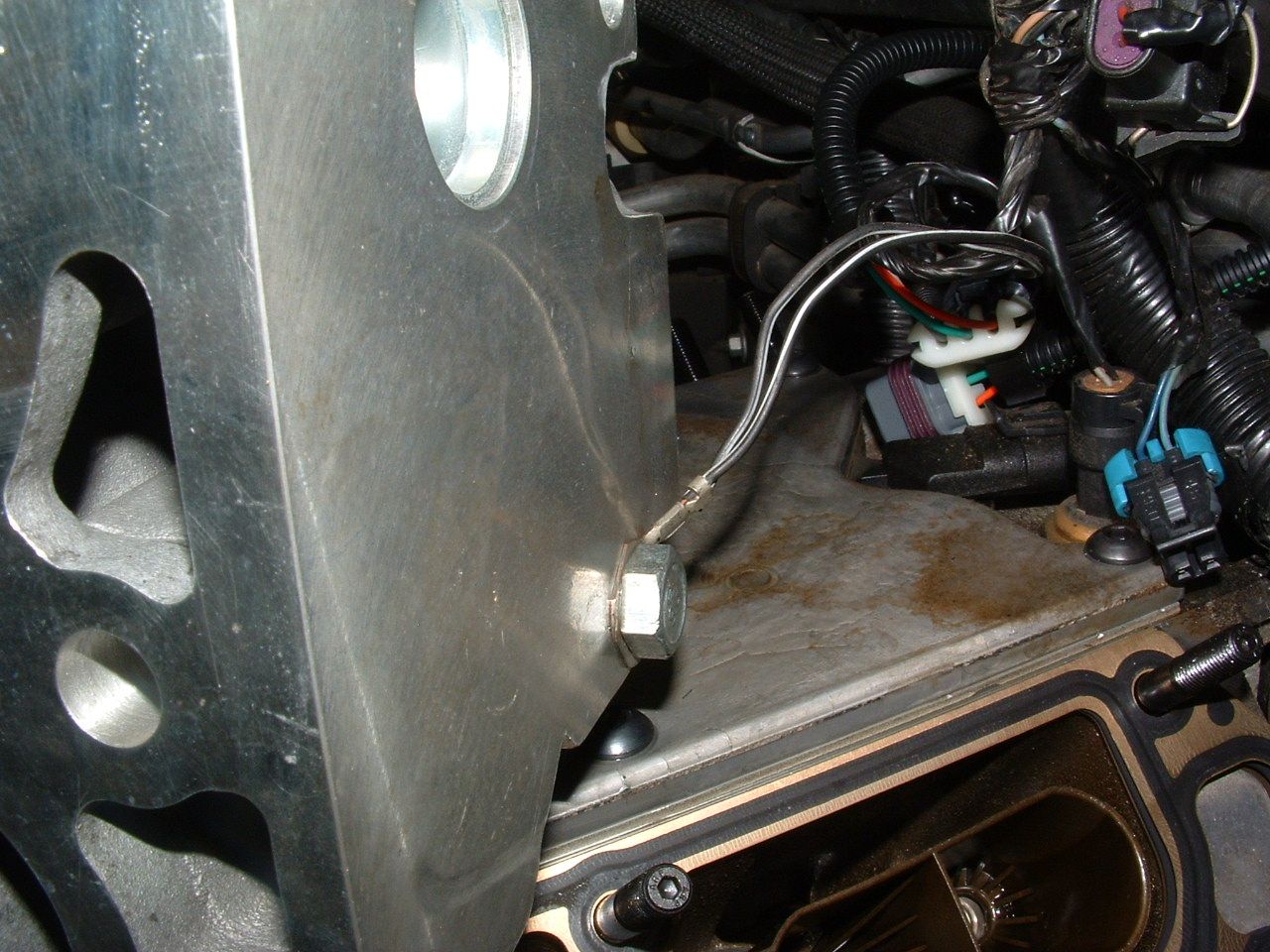
The engine wiring harness (drivers side ) runs along the head /manifold and down to the back of the engine. See if the harness is rubbing on the bracket at the back of the fuel rail and chaffed or cut:

The engine wiring harness (drivers side ) runs along the head /manifold and down to the back of the engine. See if the harness is rubbing on the bracket at the back of the fuel rail and chaffed or cut:
02-01-2013, 04:12 PM
#14
Heel & Toe
Thread Starter
Member Since: Nov 2012
Posts: 18
Likes: 0
Received 0 Likes
on
0 Posts
Yep all grounds and looms were bolted back to the heads... They were not easy,. A chaffed wire has crossed my mind and definitely something I'm gonna check. I really appreciate all the input and I'll keep updating progress..
Thanks
Thanks
 02-01-2013, 04:31 PM
#16
Tech Contributor
Member Since: Dec 1999
Location: Anthony TX
Posts: 32,736
Received 2,180 Likes
on
1,583 Posts
CI 6,7,8,9,11 Vet
St. Jude Donor '08
When the issue happens,, IMMEDIATELY read the DTCs using the DIC without turing off the ignition and post whats there...
Post ALL the DTCs. If it were me, I would read them now and record what is there now. Then CLEAR ALL the DTCs and post what returns when the issue happens. Here is how to read your DTCs from the drivers seat,
READING YOUR Engine Diagnostic Trouble Codes (DTC)
This procedure should be carried out any time you experience a problem with your C5. Most inexpensive store bought aftermarket code readers will ONLY read power train DTC�s. Reading the DTC�s with the C5 built in code reader will allow you to read ALL the modules in the vehicle.
The Diagnostic Display Mode is entered with the following procedure:
1) Turn on the ignition but don't start the engine.
2) Press the RESET button to turn off any warning messages. (i.e. door open, trunk open ect)
3) Press and hold the OPTIONS button
4) While holding OPTIONS, press FUEL button four times within a 10 -second period.
Initially, the on-board diagnostics go into an Automatic Mode which will cycle through each module and shows diagnostic codes in a pre-set sequence: PCM - TCS - RTD - BCM - IPC - RADIO - HVAC - LDCM - RDCM - SCM - RFA. All codes will be displayed for each module. ( i.e. PCM = 4 codes) If none are present in a given module, you will see No More Codes on the display.
There are two types of diagnostic codes, Current and History designated with a letter suffix, �C� or �H�. A current code indicates a malfunction is present in the module displaying data. A history code indicates a problem existed sometime in the last 40 or 50 ignition cycles. When not accompanied by a current code of the same number, it's potential evidence of a previous problem, now resolved, that was not removed by clearing the codes. More likely it's an indication of an intermittent malfunction.
Intermittent codes are the most challenging of the diagnostics. An intermittent code may have happened once, may have happened more than once but is inconsistent or may be happening on a regular basis but not at the time the codes are displayed. History codes can also be caused by a current malfunction in a system that is not operating at the time codes are displayed. An example is the rear window defogger which doesn't operate until the Body Control Module detects engine rpm. For history codes set by a module that does not operate with the key on and engine off, a special diagnostic tool called a Scan Tester is necessary to properly diagnose the malfunction.
Once the system has displayed all modules, it goes into the manual mode which allows selection of each module using combinations of Driver Information Center buttons. Manual mode can also be entered during the automatic sequence by pressing any button except E/M. Once the display shows Manual Diagnostics, select a module by pressing the OPTIONS button to go forward or the TRIP button to go back. Once a module is selected, a code is displayed, and if more than one are present; press GAGES to go forward or FUEL to go back.
To exit the diagnostic mode at any time, press E/M. If you want to erase codes in a given module, press RESET To reset the codes once in manual mode, press and hold RESET until it displays NO CODES Press OPTIONS to go to the next module. Repeat the steps until you have reset the codes in all the computer modules.
NOTE!! Only reset the codes IF you want to - it is NOT necessary to do this. Clearing a code does not repair a problem. You are simply erasing the evidence of it in the module's memory. If you clear the code/s, and extinguish the Check Engine Light, your emissions status ready will NOT allow you to pass an emissions test until you have completed the required driving cycles. There are a few body module DTC�s that if set will prevent the module from operating properly. Once the DTC is cleared, the module will return to full function. This is not true for power train DTCs.
If you have never read and cleared your codes, there will probably be a lot of old history DTCs. It is recommended that you clear your codes and see if any come back during a driving cycle. Those are the ones that you need to concentrate on diagnosing.
Once you have the codes, the next question is: What to do with the information?
First, consult the factory service manual. Any serious C5 Do-It-Yourself owner should invest in the Corvette Service Manual of the appropriate model year. The Service Manual is really a requirement if you want to understand and work on your C5.
NOTE and a WARNING. You can read the DTCs while the engine is running. I pull mine up all the time while driving.
WARNING. Don�t become distracted while reading DTCs while your driving and cause an accident!!!!! Use common sense and drive safe.
These are some very good C5 Diagnostic Trouble Code (DTC) explanation web sites!!! They also explain how to read the DTCs
Here are some very good sites that explain what DTC mean:
http://www.gearchatter.com/viewtopic11755.php
http://www.obd-codes.com/trouble_cod...d-ii-codes.php
Make sure to include the H or C suffix when you post your DTCs!!
02-04-2013, 08:13 PM
#17
Heel & Toe
Thread Starter
Member Since: Nov 2012
Posts: 18
Likes: 0
Received 0 Likes
on
0 Posts
Update to my post.... Turns out the ground on the back of the cylinder head was loose. This particular ground is responsible for all the throttle positioning motors and sensors which is why it either ran or died. A ground that I thought for sure was tight wasn't. Thank you all very very much for your help and I hope that my journey can help somebody else if ever needed... Remember these cars are very ground sensitive so dont ever take them for granted.
Thanks again Corvette Forum...
Thanks again Corvette Forum...