
Rear-gear Swap/Differential Rebuild How-To
 11-20-2011, 02:16 PM
#1
Burning Brakes

Thread Starter

I've searched high and low and never managed to find any decent how-to information on the subject of DIY rebuilding of our differentials. Whatever's out there always seems to try and scare people away because the job is apparently very tricky and requires a lot of expensive specialty tools. My aim was simply to change out my 3.42's for a set of 3.90's. That left me with two options: pay someone else to do it for me, or try and do it on my own. The first option always makes me feel a little uneasy. I'd rather understand the problem than rely on others to understand it for me. The right tools, knowledge, and a little perseverance is usually all that's needed to get er done. Unfortunately, I only had one of the three, so it actually did end up being pretty time consuming. But it doesn't have to be! After pouring through the web and the service manual, I pieced together an idea of what needs to be done. I've tried to write it down here as completely as possible in the exact order I did things. I generally followed the manual's procedures, but took a few detours of my own to simplify things and to help me understand what's actually going on.
What made this a big project in this case was that I decided to make up my own set of tools. I realize that probably no one else is going to waste their time like this, but the knowledge obtained is still definitely worth sharing. The tools can be found online for not too much money...$500, a lot of times way less, could get you everything you need. I made them myself mostly to help pass the winter, but the price was also right (0ish dollars), and the quality of custom made tools is sometimes a little better than the mass produced stuff. The first set of tools described below, what I call the "service tools", were fairly straight forward to build, but the "measurement tools" required a good understanding of what all the measurements and calculations laid out in the manual were trying to achieve. I reverse engineered these tools based on a low-mile differential known to run quietly and which exhibited a good mesh pattern on the teeth. By measuring the shims used in this differential, as well as several other internal dimensions, I was able to work backwards and figure out the dimensions the tools needed to have to yield this set-up. But, by using the factory Kent-Moore tool set, and the info laid out here, this job is surprisingly simple. The key is to take your time and make accurate measurements and calculations. The rest is simple wrenching.
A big shout out to long time forum member sami85L98. Sami's a hardcore car guy who lives and breathes Vettes day and night. Not only did he source the R&D diff for this project, but he offered up his own vette as a guinea pig for our first rebuild with these tools. We installed 4.10s and new clutches with no problems. After many runs down the track at Cayuga, his diff has proven itself to be completely trouble free and quiet. Phew...
DISCALMER: I'm not a professional. I pulled most of this out of my ***, and there may certainly be some mistakes. It's my hope that people with more knowledge and experience in the subject will chime in and add to this...this forum is a huge wealth of info, except on this subject. If you use the factory tools and procedures, you're golden...but if you start to stray like I did, you are on your own. If you do anything mentioned below and your car never moves again, it's your fault...not mine.
This endless write-up breaks down into 4 sections:
1) Tools
2) Disassembly
3) Measurement/shim selection
4) Re-assembly

The following 9 users liked this post by Its_Go_Time:
Bill Curlee (12-17-2015),
billsnogo (09-21-2022),
ericdwong (06-25-2016),
Joe_G (12-17-2015),
My2002Z06 (08-10-2020),
and 4 others liked this post.

Popular Reply
11-20-2011, 02:21 PM
Burning Brakes
Thread Starter
If you�ve made it this far, I bet you can go the rest of the way without help. Reassembling the major pieces really is the reverse of taking it all apart.
Oil all the bearings liberally, both the races and the cones. Lower the carrier into the case and seat it into the bearing race by spinning it back and forth a few times. The special GM tool comes in handy for this, but it�s not essential. Once the carrier is back in, don�t forget to install the stud along with the steel reinforcement block.
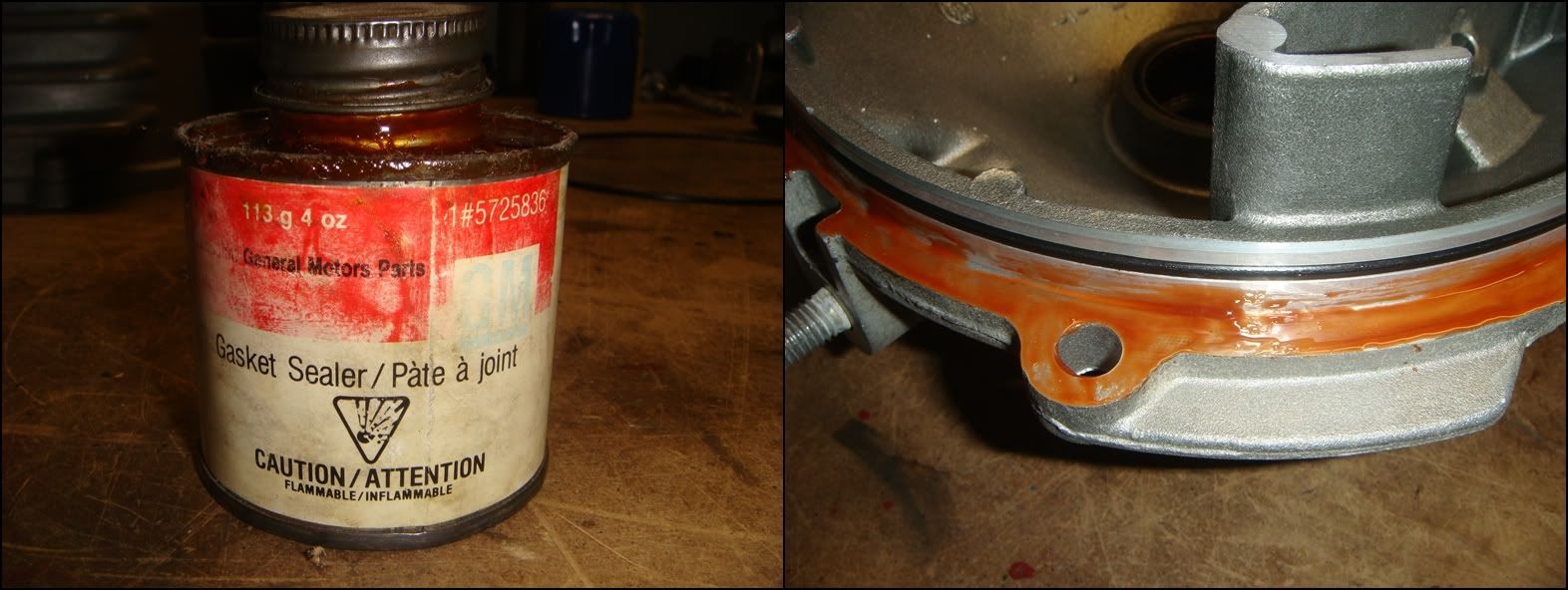
Re-install the RH cover, and apply a little sealer on the flange if you wish. By now, you should realize that if a sealer is used, it needs to be a thin one. Any thickness added here will throw off the set-up you worked so hard to achieve. The stuff shown below is pretty wicked�its very thin, and never hardens. I actually did a test with the preload tools I made to see what effect this sealer had on the overall width between the bearing bores and, with feeler gauges, it was basically immeasurable. Thick silicone might be a different story though.
Re-install the LH cover. Both left and right covers torque to 18 lb ft. Insert the pinion assembly into position(with its shims) and torque to 18 lb ft. Install the pinion cover with its O-ring.
Done.
Reference information
Bearing Numbers
Side Bearings (L&R):
Timken TS Series bearings
Inner Cones: 387A
Outer Races: 382A
Pinion Bearings:
Front:
Inner Cone: NP568415
Outer Race: NP908986
Rear:
Inner Cone: NP201062
Outer Race: NP101912
Left Side Roller Bearing:
INA HK 4020
GM Part Numbers
Bearings
C5 ZO6 Pinion Housing Assembly (complete with bearings) __________ 88984478
LH Output Shaft Needle Bearing __________ 12458146
Seals
Axle Shaft Seals __________ 88996703
Side Cover O-Rings __________ 89047953
Shafts
LH C6 ZO6 Output shaft __________ 89060119
RH C6 ZO6 Output shaft __________ 89060120
RH C6 ZO6 Side Gear __________ 19180962
RH C6 ZO6 Side Gear Retaining Ring __________ 12458084
Shims
Side shims
1.00mm 0.0393 in __________ 89060047
1.25mm 0.0492 in __________ 89060046
1.30mm 0.0511 in __________ 89060045
1.40mm 0.0551 in __________ 89060044
1.50mm 0.0590 in __________ 89060043
1.60mm 0.0629 in __________ 89060042
1.70mm 0.0669 in __________ 89060041
1.80mm 0.0708 in __________ 89060040
1.90mm 0.0748 in __________ 89060039
2.00mm 0.0787 in __________ 89060038
2.10mm 0.0826 in __________ 89060037
2.20mm 0.0866 in __________ 89060036
Torque Specs (from 2002 GM manual)
Differential Case Bolts __________ 41 lb ft
Differential-to-Transmission Bolts and Nuts __________ 37 lb ft
Drain Plug __________ 26 lb ft
Fill Plug __________ 26 lb ft
Left Side Cover Bolts __________ 18 lb ft
Pinion Housing/Cage Bolts __________ 18 lb ft
Pinion Nut __________ 370 lb ft
Rear Cover Bolts and Stud __________ 89 lb in
Right Side Cover Bolts __________ 18 lb ft
Ring Gear Bolts __________ 144 lb ft
Vehicle Speed Sensor Bolt __________ 9 lb in
Rear Axle Specifications (from 2002 GM manual)
Pinion Rotating Torque __________ 22lb in
Side Bearing Rotating Torque(No Pinion)*
New bearings 15 � 30 lb in
Old bearings 10 � 25 lb in
Ring Gear/Pinion A1 nominal Value (All Axles) __________ 4.055in
Ring Gear/Pinion A2 nominal Value (3 series Axles) __________ 2.58in
Ring Gear/Pinion A2 nominal Value (2 series Axles) __________ 2.93in
Ring Gear/Pinion Backlash __________ 0.0067-0.0082in
* Not from manual
Oil all the bearings liberally, both the races and the cones. Lower the carrier into the case and seat it into the bearing race by spinning it back and forth a few times. The special GM tool comes in handy for this, but it�s not essential. Once the carrier is back in, don�t forget to install the stud along with the steel reinforcement block.
Re-install the RH cover, and apply a little sealer on the flange if you wish. By now, you should realize that if a sealer is used, it needs to be a thin one. Any thickness added here will throw off the set-up you worked so hard to achieve. The stuff shown below is pretty wicked�its very thin, and never hardens. I actually did a test with the preload tools I made to see what effect this sealer had on the overall width between the bearing bores and, with feeler gauges, it was basically immeasurable. Thick silicone might be a different story though.
Re-install the LH cover. Both left and right covers torque to 18 lb ft. Insert the pinion assembly into position(with its shims) and torque to 18 lb ft. Install the pinion cover with its O-ring.
Done.
Reference information
Bearing Numbers
Side Bearings (L&R):
Timken TS Series bearings
Inner Cones: 387A
Outer Races: 382A
Pinion Bearings:
Front:
Inner Cone: NP568415
Outer Race: NP908986
Rear:
Inner Cone: NP201062
Outer Race: NP101912
Left Side Roller Bearing:
INA HK 4020
GM Part Numbers
Bearings
C5 ZO6 Pinion Housing Assembly (complete with bearings) __________ 88984478
LH Output Shaft Needle Bearing __________ 12458146
Seals
Axle Shaft Seals __________ 88996703
Side Cover O-Rings __________ 89047953
Shafts
LH C6 ZO6 Output shaft __________ 89060119
RH C6 ZO6 Output shaft __________ 89060120
RH C6 ZO6 Side Gear __________ 19180962
RH C6 ZO6 Side Gear Retaining Ring __________ 12458084
Shims
Side shims
1.00mm 0.0393 in __________ 89060047
1.25mm 0.0492 in __________ 89060046
1.30mm 0.0511 in __________ 89060045
1.40mm 0.0551 in __________ 89060044
1.50mm 0.0590 in __________ 89060043
1.60mm 0.0629 in __________ 89060042
1.70mm 0.0669 in __________ 89060041
1.80mm 0.0708 in __________ 89060040
1.90mm 0.0748 in __________ 89060039
2.00mm 0.0787 in __________ 89060038
2.10mm 0.0826 in __________ 89060037
2.20mm 0.0866 in __________ 89060036
Torque Specs (from 2002 GM manual)
Differential Case Bolts __________ 41 lb ft
Differential-to-Transmission Bolts and Nuts __________ 37 lb ft
Drain Plug __________ 26 lb ft
Fill Plug __________ 26 lb ft
Left Side Cover Bolts __________ 18 lb ft
Pinion Housing/Cage Bolts __________ 18 lb ft
Pinion Nut __________ 370 lb ft
Rear Cover Bolts and Stud __________ 89 lb in
Right Side Cover Bolts __________ 18 lb ft
Ring Gear Bolts __________ 144 lb ft
Vehicle Speed Sensor Bolt __________ 9 lb in
Rear Axle Specifications (from 2002 GM manual)
Pinion Rotating Torque __________ 22lb in
Side Bearing Rotating Torque(No Pinion)*
New bearings 15 � 30 lb in
Old bearings 10 � 25 lb in
Ring Gear/Pinion A1 nominal Value (All Axles) __________ 4.055in
Ring Gear/Pinion A2 nominal Value (3 series Axles) __________ 2.58in
Ring Gear/Pinion A2 nominal Value (2 series Axles) __________ 2.93in
Ring Gear/Pinion Backlash __________ 0.0067-0.0082in
* Not from manual
11-20-2011, 02:16 PM
#2
Burning Brakes
Thread Starter
I've broken the official tool list for the Getrag 625 into two groups: "Measurement tools" and "Service tools". The measurement tools are used to determine the thickness of the three shim-stacks which set the bearing preload and gear mesh/backlash. The service tools are used for assembly and disassembly of the differential. Pictured below are the GM tools, along with my homemade counterparts. I've included simple sketches of these tools for anyone who's interested. I'll freely admit that I'm not a professional designer, and it shows big time in these drawings. They don't show every single detail, but all the critical dimensions should be there. The homemade tools are not exact copies of the originals, but still get the job done. One important point: the measurement tools have to be used together, as many of them relate to each other dimensionally...With these, it's either all GM or all made to the dimensions shown below.
SERVICE TOOLS.
The service tools are used to take apart and reassemble the differential. Here they are with GMs description of what they do, along with some extra notes of my own:
J-42159 DIFFERENTIAL SIDE BEARING REMOVER.
Due to the design of the differential unit, there is limited access to the right side differential carrier cover bearing. This tool provides the access to remove the bearing without damaging the differential unit. IMHO, the best way to remove a bearing from a shaft without damaging it is to support it by its inner race while the shaft is being pressed out. Unfortunately, there is just no way to do this on the side bearings in this differential. The RH bearing is especially hard to get around. This tool sneaks behind the two bearings as much as possible, but it still bears against the cage which keeps the rollers from falling out. With these tools, the force used to pull the bearing off the shaft is transferred from the cage to the inner race thru the rollers. Pressing the bearings off like this risks screwing them up. If they are in rough shape and are being replaced, fine...but if you plan on re-using them, don�t risk doing any damage and just leave them alone. A simple gear change doesn't require removing these bearings.
Dimensioned Sketch
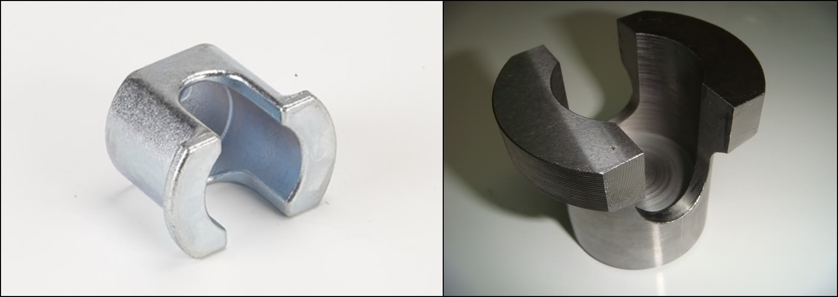
J-42166 FRONT PINION BEARING REMOVER.
1997-Current Y-Car. Due to the drive pinion and housing design, there is limited access for removal of the front pinion bearing. This tool is required to provide access for front pinion bearing removal, and is used along with tool J-42162 to prevent damage to the drive pinion. This tool is placed around the front drive pinion bearing and is placed into a hydraulic press. The J-42162 is placed over the nose of the pinion, and the bearing is pressed off of the drive pinion. Same as above, but this time the bearing must be removed if a gear swap is being done. There's one problem here: the preload of the pinion bearings is controlled by a selective spacer which, to my knowledge, is not available separately. GM requires you to replace the entire assembly: bearings, spacer and housing. So do yourself a favour and press the old one off carefully!
Dimensioned Sketch
J-42162 SIDE GEAR COMPRESSOR.
Required to compress the limited slip clutch pack in order to remove and install the cross pin from the right side differential case. This tool is also used to remove and install the differential case side bearings and drive pinion bearings over the output stub shafts. Tool J-42162 is also used with a hydraulic press to compress the limited slip clutch pack to allow removal of the differential cross pin. This is the first of several multi-function tools in this kit. First, it�s used with the two bearing holders above to remove the two side bearings and the rear pinion bearing. With the help of a press, this tool pushes the shafts out from inside the bearing. Second, it�s used to push the RH side gear down against the preload spring behind it. This unloads the spider gear cross-shaft, allowing it to be removed.
Dimensioned Sketch
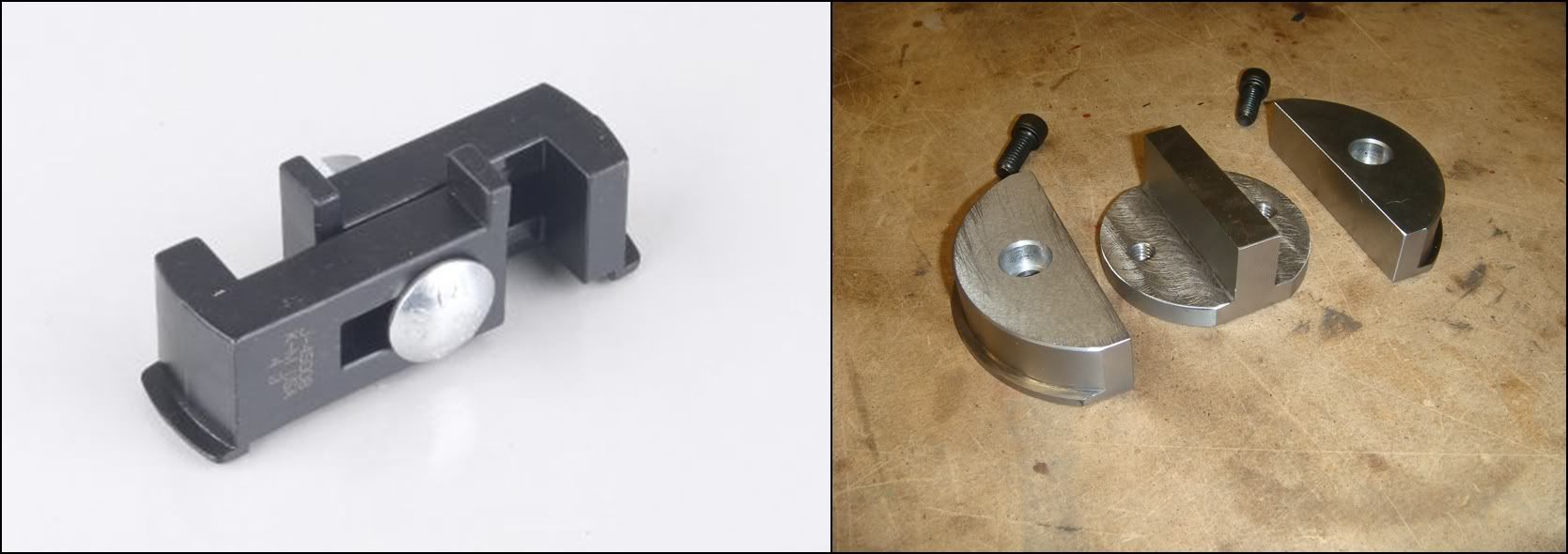
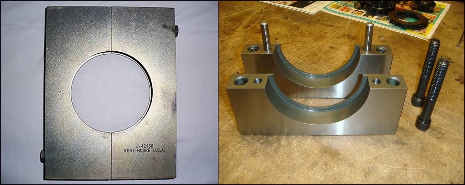
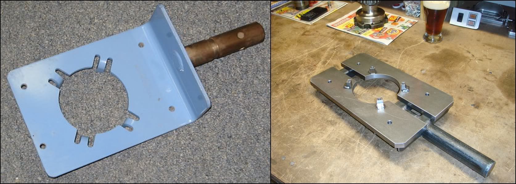
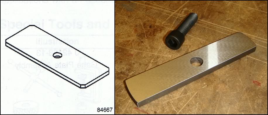
J-42194 BEARING RACE REMOVER.
1997-Current Y-Car. Due to the design of the differential side covers, there is limited access to remove the side cover bearing races for service. This tool provides access to the side cover bearing races, and is used with a hydraulic press to remove the races. The tool is inserted into the side cover and placed under a bearing race. The tool is tightened into place under the bearing race, and provides a suitable surface for use with a hydraulic press. This J-tool was probably designed to work on several different applications, hence its narrowness. The tool I made will only work on these two bearings, so I made it a lot bigger for more contact area...less chance of busting off those thin lips. The two half-round pieces are inserted into the race and hooked in so the lips bear on the underside of the race. The middle piece is then slipped in from the other side, with the two screws holding it rigid. Pressing down against this assembly will push the race from its bore. This tool is also required to remove the front pinion bearing race, which is considerably larger than the side bearings. If I had known that from the beginning, I would have just copied the *adjustable* factory tool. Instead, I had to make a second dedicated pinion tool�looks the same, just bigger.
Dimensioned Sketch
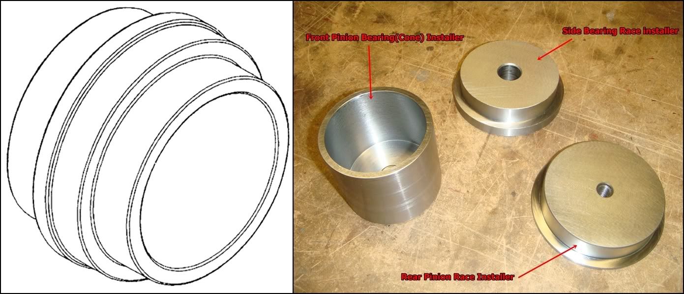
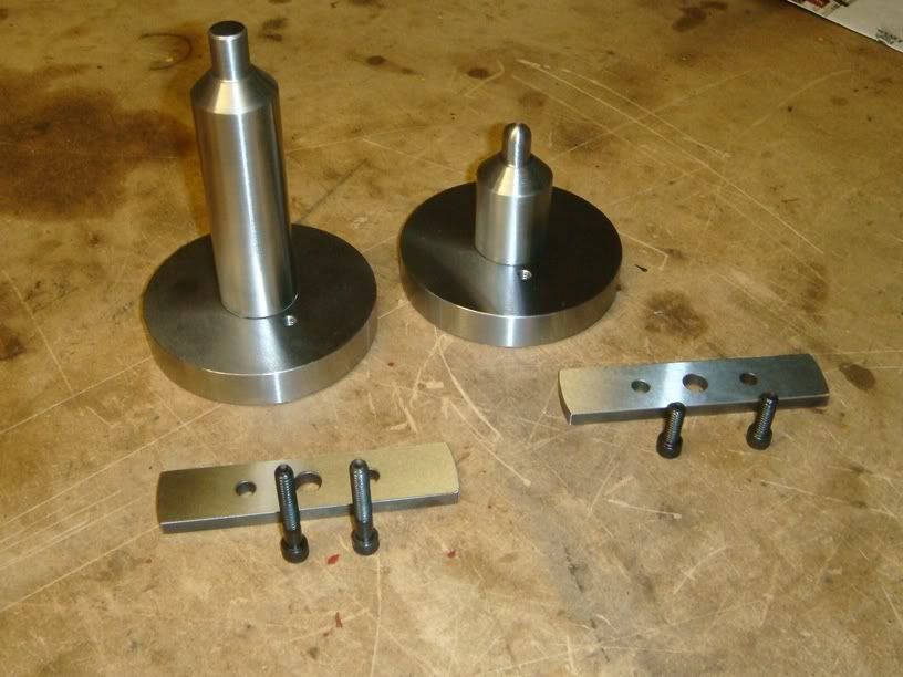
J-42170 BEARING AND RACE INSTALLER.
1997-Current Y-Car. Tool J-42170 is required to install the drive pinion rear bearing race to the correct depth in the drive pinion housing, and to install the front drive pinion bearing onto the drive pinion. This tool is also required to install the differential case side bearings to the differential unit. The tool is used with a hydraulic press to install the drive pinion rear bearing inner race to the drive pinion housing, and to install the differential case side bearings to the differential unit. This tool is used with tool J-42164 when installing the front drive pinion bearing, to prevent damage to the drive pinion. This is the second multi-function tool. I broke it down into 3 separate tools. The cylinder on the left is used to press the two pinion bearings back onto the pinion. As the bearings press on, the pinion shaft will begin to protrude from the top of the bearing, and this hollow cylinder gives it somewhere to go. The bearings will bottom out on the pinion before the end of the pinion bottoms out in the cylinder. The other two tools are just simple bushing drivers. They fit inside the bearing races and give the press a surface to push against.
Dimensioned Sketch
J-42172 BEARING RACE INSTALLER/SPANNER WRENCH.
1997-Current Y-Car. The spanner side of tool J-42172 is required to remove and install the drive pinion nut from the drive pinion. The opposite side of this tool is required to install the drive pinion front bearing inner race to the drive pinion housing, and to install the side cover bearings into the left and right side covers. The tool is used with a hydraulic press to install the side cover bearings and the drive pinion front bearing inner race. This tool is used with tool J-42164 to remove the drive pinion nut, and with a torque wrench to install the drive pinion nut, to prevent damage to the drive pinion. The nut that holds the pinion assembly together doesn�t have flats on it. Instead, it has 6 holes drilled around the perimeter into which this tool locks into. The 10� ratchet in the picture is wishful thinking, though. This nut is very tight, and the stake that keeps it from loosening off is hard to clear completely. Sooo, a big �� drive impact gun might be your best friend here. The first time I removed this nut, it took me about 30mins to get off, using a long breaker bar with a pipe on the end. My bench vise actually started turning on it's swivel, no matter how tight I locked it down. The second nut I did took about 5 seconds with an impact gun.
Dimensioned Sketch
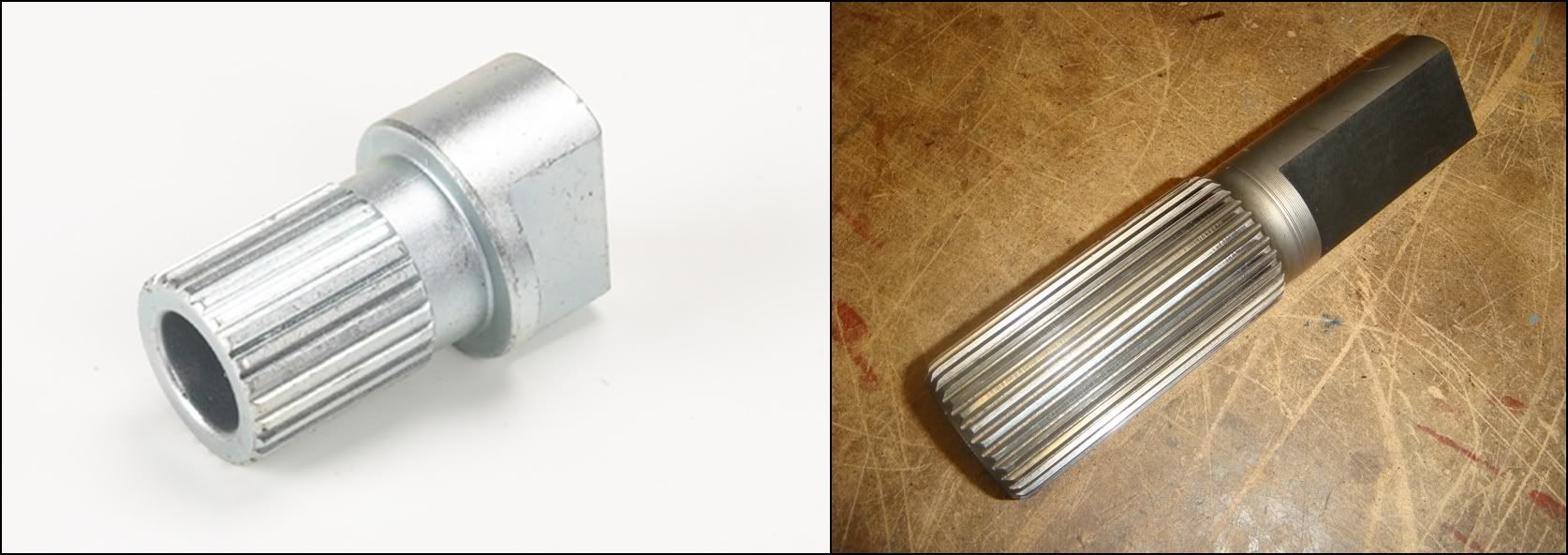
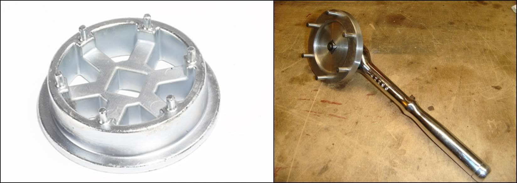
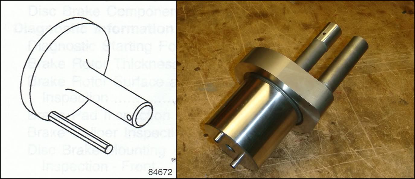
J-42164 PINION GEAR HOLDER.
1997-Current Y-Car. Tool J-42164 is used to hold the drive pinion during drive pinion assembly/disassembly and to back up the pinion during bearing installation. This tool is also used to measure pinion rotating torque. Without the tool, pinion damage will occur. Use with tool J-42172 to loosen/tighten the drive pinion nut. Use with tool J-42170 to prevent damage to the drive pinion gear when installing the front and rear pinion bearings. Use with a torque wrench to measure the pinion rotating torque during reassembly to prevent damage to the ring and pinion. This tool can be made from any splined shaft with 27 splines and an OD of 1.375�. I used an old output shaft from an ancient Turbo 350 automatic tranny, cut it to size and ground a couple of flats on it so it wouldn�t spin in my vise. The pinion lock nut has to be torqued to 370 lb-ft�without this tool, you�re gonna have a fun time holding the pinion from turning. It�s also used to support the pinion while the bearings are being pressed on to it, so the pinion teeth don�t bear against the press at all.
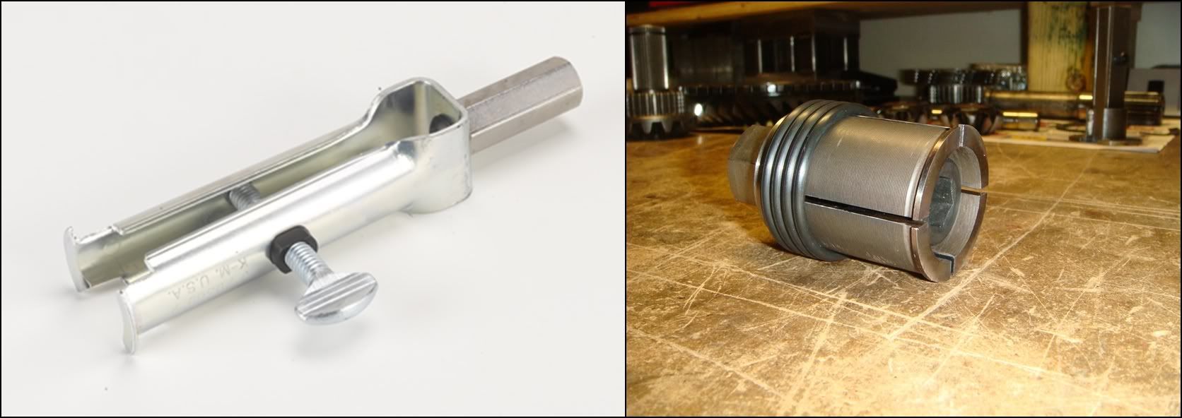
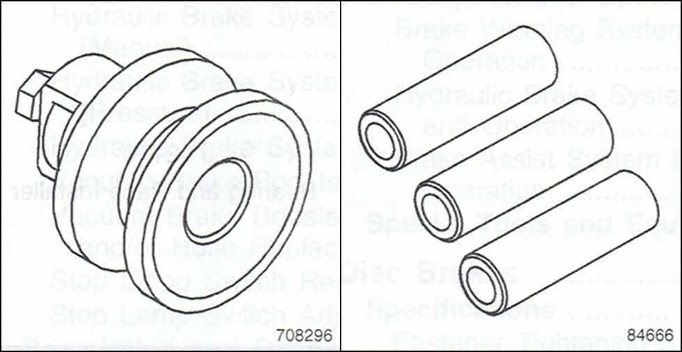
J-29369-2 LEFT OUTPUT SHAFT BEARING REMOVER.
The output shaft on the right side of the PTU is supported by a needle bearing inside the ring gear hub. The diameter of the hub prevents needle bearing removal using conventional methods, i.e., hammer and brass drift. J-29369-2 is placed through the needle bearing, and its thumb screw is tightened to expand it under the needle bearing race. J-02619-A Slide Hammer is attached to J-29369-2 and used to remove the needle bearing without damage to the ring gear hub. Maybe GM copied that part out of a 4x4 manual that happens to use this same tool? These rear-ends use a needle bearing to support the extra long LH output shaft, and this is the tool used to pull it out from its bore. It slides into the bearing from the inside and gets expanded out until it gets a good hold. The factory tool shown on the left is then connected to a slide hammer, which will pull the bearing free. The alternate version on the right uses a press to push the bearing out from the outside.
Dimensioned Sketch
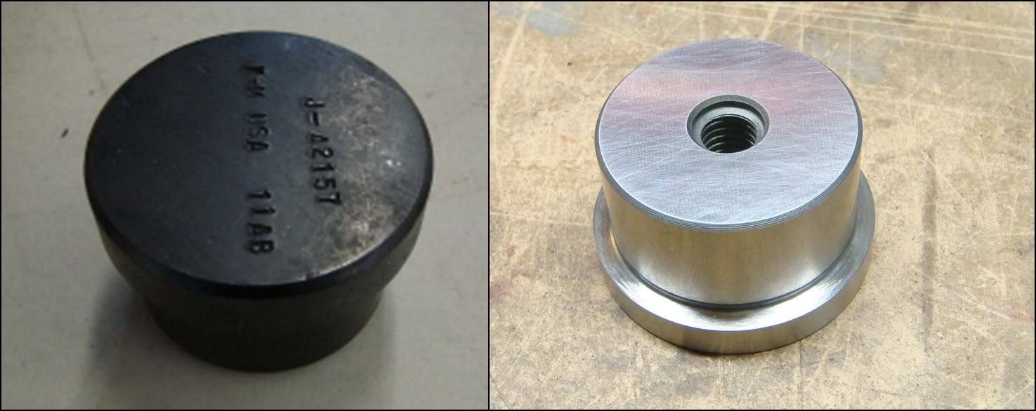
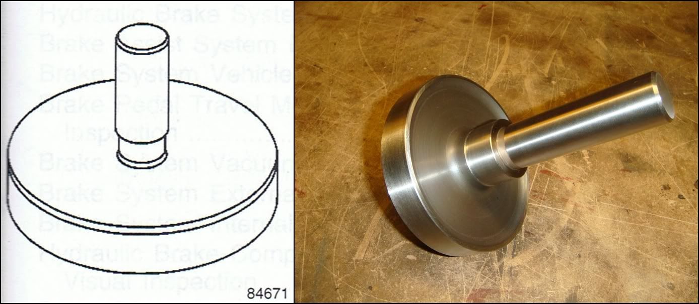
J-42157 LEFT OUTPUT SHAFT BEARING INSTALLER.
The left output shaft bearing is pressed into the left side cover of the axle assembly. This tool is used with a hydraulic press to properly install the left output shaft bearing. This tool is used to drive in the needle bearing which helps support the longer LH output shaft. The bearing just slips over the tool and gets pressed into the case with a hydraulic press.
Dimensioned Sketch
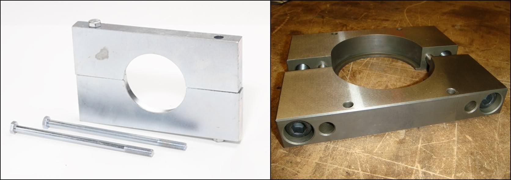
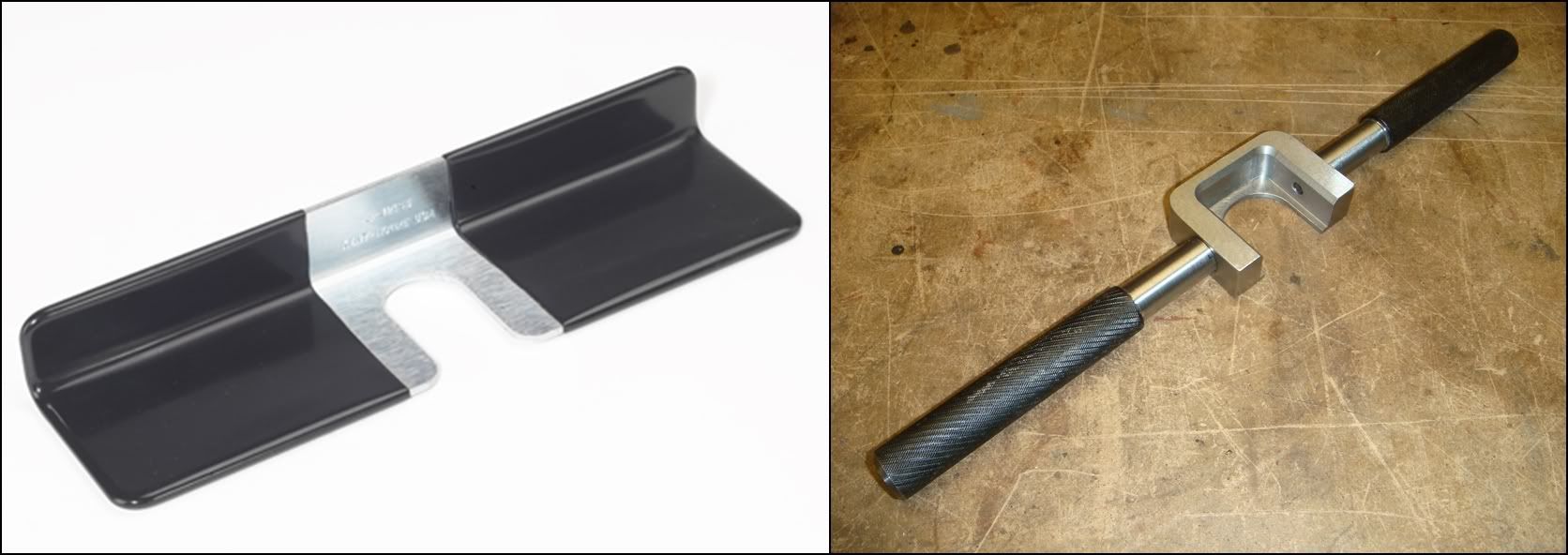
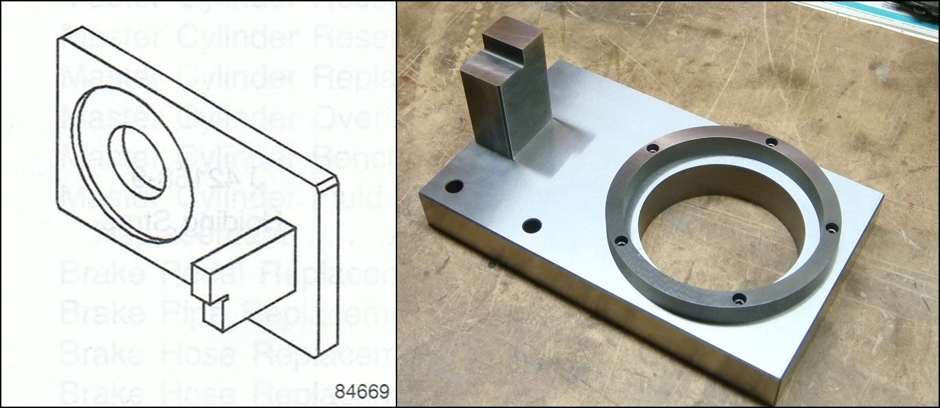
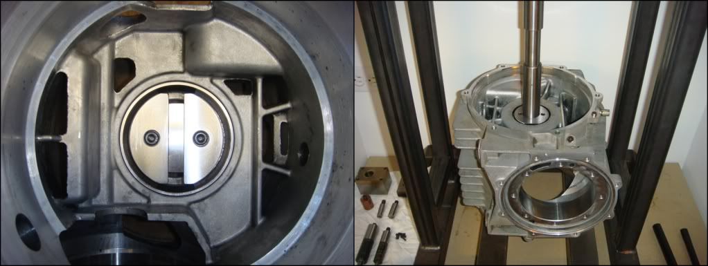
J-42173 DIFFERENTIAL HOLDING FIXTURE.
1997 -Current Y-Car. Tool J-42173 is used to hold the differential case assembly to prevent damage to the ring gear during unit repair service. This tool also holds the housing for reassembly. The tool is used with a bench vice to hold the differential case assembly to prevent damage to the ring gear during unit repair service. This tool seems to have two purposes: To support the disassembled case on it driver�s-side-cover surface while working on it, and supporting the differential carrier unit while work is done on it. The four holes along the outside are used to secure the case to the holding fixture. The LH cover is removed from the case, and then the case is lowered onto the fixture and bolted down. Personally, I prefer to have the case sliding around loose on the bench while I�m working on it. The second use of this tool is way more useful; to support and lock the carrier from turning while the ring gear bolts and housing bolts are being worked with. The four prongs on the top surface engage with the cast-iron part of the carrier housing and hold it from turning while the bolts are being worked on. Without it, you�re left clamping the carrier into a vice and holding it from turning with one row of screws, while trying to loosen or tighten the others.
Dimensioned Sketch
J-42155 DIFFERENTIAL LIFTING TOOL.
1997-Current Y-car. The differential case must be removed from the rear axle housing for unit repair service. This tool allows the heavy (approximately 60 lbs.) differential unit to be safely removed from and installed into the axle housing. Once the C-clip is removed, the tool is inserted into the groove of the right output shaft. The technician can then safely remove the differential from the axle housing. Once service is complete, tool J-42155 allows the technician to safely reinstall the differential unit, without damage to the rear axle assembly. This tool isn't absolutely necessary, as can be judged by the crappyness of the GM piece. Without this tool, you can lower the differential carrier into the case from above, and when the long shaft pops out the bottom, just grab it to lower it the rest of the way. This tool just makes it go a little smoother. This tool, in conjunction with J-42173 above, allows you to remove and install the guts without scratching-up the inside of the case or your fingers. Dimensioned Sketch
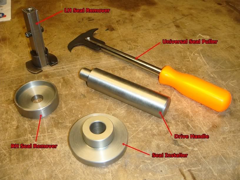
OIL SEAL TOOLS.
The one with the orange handle will do everything you need, and it cost me $9.99. It�s especially useful if there are shafts sticking out, like you would see if you were changing the seals with the diff in the car. It basically pries the bushing out, wrecking it in the process. Don�t re-use seals yanked with one of these things. Retentively speaking, the aluminum seal-bore could get damaged a little with this prying. The two homemade seal removers shown on the left will remove the seals without causing any damage to either the seals or the case. The installation tool just helps push the seals in straight.
MEASURMENT TOOLS..
These tools are used to calculate shim stack thicknesses to set proper bearing preloads and gear mesh. They are packaged as a kit, J-42168. Here's a breakdown of the individual tools within the kit:
J-42168-1 DIFFERENTIAL CENTERLINE CYLINDER.
This tool, in conjunction with J-42168-2 and J-42168-11, is used for calculating the shims required to set the depth of the pinion. The pinion can be positioned forward/aft in the case by the use of shims. This positioning controls how it meshes with the ring gear. The job of this tool is simply to extend the centerline of the LH bearing bore out under the pinion bore. J-42168-2, which is inserted into the pinion bore, has a gauge pin which comes down to meet this extended centerline. By feeler-gauging the gap between the two, the location to the pinion with respect to the axle centerline can be determined. The most important thing about this tool is that everything is kept concentric with the bearing bore. The tool should also fit as snuggly as possible into the bore for the most accurate measurements. Dimensioned Sketch
J-42168-9 HOLDING STRAP.
This simply holds the centerline cylinder firmly in the left side bearing bore. The cylinder slips into the bore from inside, and this strap bridges the bore on the outside, with the screw holding them together snuggly in the case. Dimensioned Sketch
J-42168-2 SHIM GAUGE ASSEMBLY.
This bad-boy, in conjunction with J-42168-1, set 2 of the three shim stacks in this differential, and completely controls how the ring and pinion mesh together. Its two probes measure both the L-R distance between the ring and the pinion, as well as the reference fwd/aft distance of the pinion with respect to the ring gear. In this photo, the upper probe with the little hole in it sets the L-R dimension, while the other probe sets the in-out setting.
J-42168-11 PINION HOUSING CENTERING SPACER.
This tool is used in conjunction with J-42168-2 above. The homemade version of J-42168-2 eliminates this two-piece arrangement.
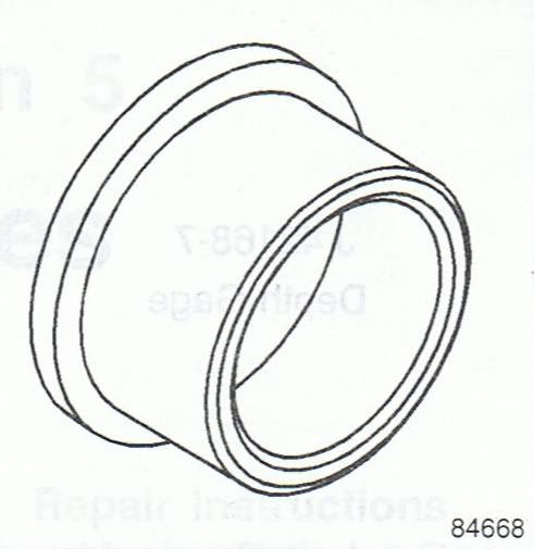
J-42168-7 DEPTH GAUGE.
This is sort of a simple �transfer tool�, used to take a depth reading inside the case and �move� it to the tool shown below, where the actual measurement is taken. First, it�s set to the distance from the top of the longer of the two probes on J-42168-2 to the bottom of the LH bearing bore. Then, it�s removed from the case and positioned on the ring gear/carrier which has been set up on the gauge plate J-42168-13. A feeler measurement is then taken between the end of the gauge pin and the gauge block. The factory tool fits into one of two oil slots in the side of the carrier, and is held in position by �jamming� it in. This tool rests against a different part of the ring gear, and is held in position with an embedded magnet.
J-42168-13 GAUGE PLATE ASSEMBLY.
This is basically just a fancy "surface plate" used to take an accurate measurement of the distance between the ring gear and the LH bearing. The LH bearing race is dropped into the round opening, and then the carrier unit, with bearings and ring gear installed is lowered into position over the race. After turning the carrier back and forth a few times to seat the bearing, the ring gear is now positioned perfectly parallel to the plate�s top surface. The �gauge block� on the side is where the measurements are taken from: the upper level is used for 2 series (2.73) carriers, while the lower level is used for all 3(and 4) series carriers. The height difference between the two levels is .350� which, not coincidently, is the difference in width between 2.73 ring gears and all the others. The 2.73 ring is wider, but the pinion is in the same location for all ratios, which means the mounting flange on the carrier needs to be moved .35� to the right to accommodate the extra thickness. This is why we can�t just slap 3.42s (or any other ratio) into a 2.73 diff�either the entire carrier has to be replaced, a special thicker ring gear needs to be used, or a spacer used between the ring and carrier.
Dimensioned Sketch
J-42168-15 SIDE BEARING SHIM SELECTOR, and J-42168-16 SPACERS
These two tools work together to give the RH shim stack thickness, which is used to set the preload on the side bearings. On the left is J-42168-15 SIDE BEARING SHIM SELECTOR, while J-42168-16 SPACERS is on the right. After the LH shims have been selected and installed behind the LH bearing race, the carrier is lowered into the case. The RH race is then placed over the RH bearing and J-42168-15 is then placed over the race. The RH cover is then reinstalled over everything, with the three spacers spacing it away from the case. J-42168-15 pokes out thru the case and produces a small gap which needs to be feeler gauged. This feeler dimension is the RH shim thickness. This tool won�t tell you how much pre-load is being added; it simply gives us the overall shim thickness for the RH side. The pre-load value is �built-in� to the tool. I didn�t make this tool, and instead decided to measure and set the pre-load directly. See below�
ADDITIONAL MEASURMENT TOOLS.
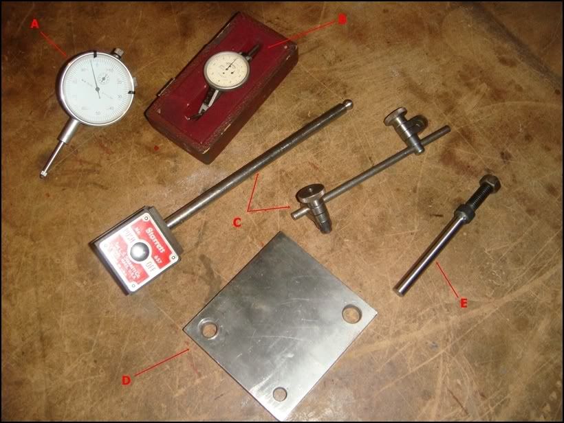
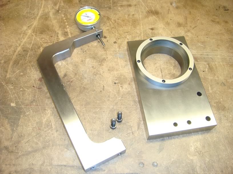
DIAL GAUGES/ ACCESSORIES FOR MEASURING GEAR BACKLASH.
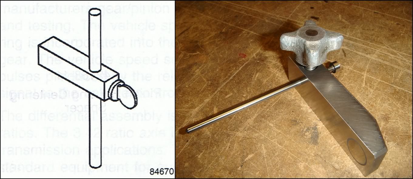
You will need a dial indicator of some kind to measure the backlash between the gears. This is a very important measurement, and you can expect a lot of gear noise and accelerated wear if it�s not done properly. Luckily, it�s very easy to do. But you�ll have to buy or borrow one of these. In the pic above, �A� is a basic AGD-2 style indicator. It has a 2 1/4� diameter face, 1� of plunger travel, and .001� resolution. These things are stupid cheap ($15-20) from places like Harbor Freight. �B� is what�s known as a Dial Test Indicator, and is much better suited for this job. Ideally, you want the indicator�s plunger to be perfectly perpendicular with the gear tooth; any angle here will create an error in your reading. The dial test indicator can achieve this but the AGD-2 can�t because of its size and plunger configuration. �A� will definitely work well enough if it�s set up properly, however �B� will cost you at least $100 for a no-name brand. Unless you can borrow a test indicator, I�d probably just stick with �A�. Now you�ll need a way to mount the indicator to the differential case. �C� is a magnetic base indicator holder. The square box holds a magnet which will stick to any ferrous material; the indicator connects to the adjustable arm. Unfortunately, our differential is made from aluminum, so this holder won�t stick. This is where something like �D� comes in handy. It�s simply a steel plate with some random holes drilled through it. It can be bolted to any available hole on the case, giving the magnetic holder something to stick to. A second option for mounting the indicator is �E�. This thing bolts into one of the mounting holes on the front face of this diff. The arm from �C� then connects directly to this pin, eliminating the magnetic base/steel plate all together. You can make your own by using 4� of 3/8-16 threaded rod, with a couple of nuts to hold it to the case.
There are two more special tools I made to help us measure side bearing preload. Once we had these, we realized we didn't need J-42168-15 or J-42168-16 which accomplish the same thing. If you are using the factory tools, you don't really need to worry about these. They're just a different way of achieving the same thing.
The first is a gauge used to determine the distance between the bearing bores in the case and side cover. A gauge fits into each bore, and is held in place with a strap from the other side. When the side cover is fitted back onto the main case, the gauges will come within .010-.030 of each other. Knowing the exact length of each gauge, plus the feeler dimension between them, the overall width can be calculated.
The second is an attachment to the gauge plate J-42168-13 mentioned above. It measures the overall width of the rotating assembly that fits into the case bearing bores. The differential carrier, with both bearings and outer races in place, is placed onto the gauge plate. The round puck is then placed on top and a press adds a little preload to make sure the bearings are seated properly. The dial indicator then gives the overall width of the entire assembly. This dimension, plus the RH and LH shim stacks must be GREATER than the case width to achieve preload on the bearings.
SERVICE TOOLS.
The service tools are used to take apart and reassemble the differential. Here they are with GMs description of what they do, along with some extra notes of my own:
J-42159 DIFFERENTIAL SIDE BEARING REMOVER.
Due to the design of the differential unit, there is limited access to the right side differential carrier cover bearing. This tool provides the access to remove the bearing without damaging the differential unit. IMHO, the best way to remove a bearing from a shaft without damaging it is to support it by its inner race while the shaft is being pressed out. Unfortunately, there is just no way to do this on the side bearings in this differential. The RH bearing is especially hard to get around. This tool sneaks behind the two bearings as much as possible, but it still bears against the cage which keeps the rollers from falling out. With these tools, the force used to pull the bearing off the shaft is transferred from the cage to the inner race thru the rollers. Pressing the bearings off like this risks screwing them up. If they are in rough shape and are being replaced, fine...but if you plan on re-using them, don�t risk doing any damage and just leave them alone. A simple gear change doesn't require removing these bearings.
Dimensioned Sketch
J-42166 FRONT PINION BEARING REMOVER.
1997-Current Y-Car. Due to the drive pinion and housing design, there is limited access for removal of the front pinion bearing. This tool is required to provide access for front pinion bearing removal, and is used along with tool J-42162 to prevent damage to the drive pinion. This tool is placed around the front drive pinion bearing and is placed into a hydraulic press. The J-42162 is placed over the nose of the pinion, and the bearing is pressed off of the drive pinion. Same as above, but this time the bearing must be removed if a gear swap is being done. There's one problem here: the preload of the pinion bearings is controlled by a selective spacer which, to my knowledge, is not available separately. GM requires you to replace the entire assembly: bearings, spacer and housing. So do yourself a favour and press the old one off carefully!
Dimensioned Sketch
J-42162 SIDE GEAR COMPRESSOR.
Required to compress the limited slip clutch pack in order to remove and install the cross pin from the right side differential case. This tool is also used to remove and install the differential case side bearings and drive pinion bearings over the output stub shafts. Tool J-42162 is also used with a hydraulic press to compress the limited slip clutch pack to allow removal of the differential cross pin. This is the first of several multi-function tools in this kit. First, it�s used with the two bearing holders above to remove the two side bearings and the rear pinion bearing. With the help of a press, this tool pushes the shafts out from inside the bearing. Second, it�s used to push the RH side gear down against the preload spring behind it. This unloads the spider gear cross-shaft, allowing it to be removed.
Dimensioned Sketch
J-42194 BEARING RACE REMOVER.
1997-Current Y-Car. Due to the design of the differential side covers, there is limited access to remove the side cover bearing races for service. This tool provides access to the side cover bearing races, and is used with a hydraulic press to remove the races. The tool is inserted into the side cover and placed under a bearing race. The tool is tightened into place under the bearing race, and provides a suitable surface for use with a hydraulic press. This J-tool was probably designed to work on several different applications, hence its narrowness. The tool I made will only work on these two bearings, so I made it a lot bigger for more contact area...less chance of busting off those thin lips. The two half-round pieces are inserted into the race and hooked in so the lips bear on the underside of the race. The middle piece is then slipped in from the other side, with the two screws holding it rigid. Pressing down against this assembly will push the race from its bore. This tool is also required to remove the front pinion bearing race, which is considerably larger than the side bearings. If I had known that from the beginning, I would have just copied the *adjustable* factory tool. Instead, I had to make a second dedicated pinion tool�looks the same, just bigger.
Dimensioned Sketch
J-42170 BEARING AND RACE INSTALLER.
1997-Current Y-Car. Tool J-42170 is required to install the drive pinion rear bearing race to the correct depth in the drive pinion housing, and to install the front drive pinion bearing onto the drive pinion. This tool is also required to install the differential case side bearings to the differential unit. The tool is used with a hydraulic press to install the drive pinion rear bearing inner race to the drive pinion housing, and to install the differential case side bearings to the differential unit. This tool is used with tool J-42164 when installing the front drive pinion bearing, to prevent damage to the drive pinion. This is the second multi-function tool. I broke it down into 3 separate tools. The cylinder on the left is used to press the two pinion bearings back onto the pinion. As the bearings press on, the pinion shaft will begin to protrude from the top of the bearing, and this hollow cylinder gives it somewhere to go. The bearings will bottom out on the pinion before the end of the pinion bottoms out in the cylinder. The other two tools are just simple bushing drivers. They fit inside the bearing races and give the press a surface to push against.
Dimensioned Sketch
J-42172 BEARING RACE INSTALLER/SPANNER WRENCH.
1997-Current Y-Car. The spanner side of tool J-42172 is required to remove and install the drive pinion nut from the drive pinion. The opposite side of this tool is required to install the drive pinion front bearing inner race to the drive pinion housing, and to install the side cover bearings into the left and right side covers. The tool is used with a hydraulic press to install the side cover bearings and the drive pinion front bearing inner race. This tool is used with tool J-42164 to remove the drive pinion nut, and with a torque wrench to install the drive pinion nut, to prevent damage to the drive pinion. The nut that holds the pinion assembly together doesn�t have flats on it. Instead, it has 6 holes drilled around the perimeter into which this tool locks into. The 10� ratchet in the picture is wishful thinking, though. This nut is very tight, and the stake that keeps it from loosening off is hard to clear completely. Sooo, a big �� drive impact gun might be your best friend here. The first time I removed this nut, it took me about 30mins to get off, using a long breaker bar with a pipe on the end. My bench vise actually started turning on it's swivel, no matter how tight I locked it down. The second nut I did took about 5 seconds with an impact gun.
Dimensioned Sketch
J-42164 PINION GEAR HOLDER.
1997-Current Y-Car. Tool J-42164 is used to hold the drive pinion during drive pinion assembly/disassembly and to back up the pinion during bearing installation. This tool is also used to measure pinion rotating torque. Without the tool, pinion damage will occur. Use with tool J-42172 to loosen/tighten the drive pinion nut. Use with tool J-42170 to prevent damage to the drive pinion gear when installing the front and rear pinion bearings. Use with a torque wrench to measure the pinion rotating torque during reassembly to prevent damage to the ring and pinion. This tool can be made from any splined shaft with 27 splines and an OD of 1.375�. I used an old output shaft from an ancient Turbo 350 automatic tranny, cut it to size and ground a couple of flats on it so it wouldn�t spin in my vise. The pinion lock nut has to be torqued to 370 lb-ft�without this tool, you�re gonna have a fun time holding the pinion from turning. It�s also used to support the pinion while the bearings are being pressed on to it, so the pinion teeth don�t bear against the press at all.
J-29369-2 LEFT OUTPUT SHAFT BEARING REMOVER.
The output shaft on the right side of the PTU is supported by a needle bearing inside the ring gear hub. The diameter of the hub prevents needle bearing removal using conventional methods, i.e., hammer and brass drift. J-29369-2 is placed through the needle bearing, and its thumb screw is tightened to expand it under the needle bearing race. J-02619-A Slide Hammer is attached to J-29369-2 and used to remove the needle bearing without damage to the ring gear hub. Maybe GM copied that part out of a 4x4 manual that happens to use this same tool? These rear-ends use a needle bearing to support the extra long LH output shaft, and this is the tool used to pull it out from its bore. It slides into the bearing from the inside and gets expanded out until it gets a good hold. The factory tool shown on the left is then connected to a slide hammer, which will pull the bearing free. The alternate version on the right uses a press to push the bearing out from the outside.
Dimensioned Sketch
J-42157 LEFT OUTPUT SHAFT BEARING INSTALLER.
The left output shaft bearing is pressed into the left side cover of the axle assembly. This tool is used with a hydraulic press to properly install the left output shaft bearing. This tool is used to drive in the needle bearing which helps support the longer LH output shaft. The bearing just slips over the tool and gets pressed into the case with a hydraulic press.
Dimensioned Sketch
J-42173 DIFFERENTIAL HOLDING FIXTURE.
1997 -Current Y-Car. Tool J-42173 is used to hold the differential case assembly to prevent damage to the ring gear during unit repair service. This tool also holds the housing for reassembly. The tool is used with a bench vice to hold the differential case assembly to prevent damage to the ring gear during unit repair service. This tool seems to have two purposes: To support the disassembled case on it driver�s-side-cover surface while working on it, and supporting the differential carrier unit while work is done on it. The four holes along the outside are used to secure the case to the holding fixture. The LH cover is removed from the case, and then the case is lowered onto the fixture and bolted down. Personally, I prefer to have the case sliding around loose on the bench while I�m working on it. The second use of this tool is way more useful; to support and lock the carrier from turning while the ring gear bolts and housing bolts are being worked with. The four prongs on the top surface engage with the cast-iron part of the carrier housing and hold it from turning while the bolts are being worked on. Without it, you�re left clamping the carrier into a vice and holding it from turning with one row of screws, while trying to loosen or tighten the others.
Dimensioned Sketch
J-42155 DIFFERENTIAL LIFTING TOOL.
1997-Current Y-car. The differential case must be removed from the rear axle housing for unit repair service. This tool allows the heavy (approximately 60 lbs.) differential unit to be safely removed from and installed into the axle housing. Once the C-clip is removed, the tool is inserted into the groove of the right output shaft. The technician can then safely remove the differential from the axle housing. Once service is complete, tool J-42155 allows the technician to safely reinstall the differential unit, without damage to the rear axle assembly. This tool isn't absolutely necessary, as can be judged by the crappyness of the GM piece. Without this tool, you can lower the differential carrier into the case from above, and when the long shaft pops out the bottom, just grab it to lower it the rest of the way. This tool just makes it go a little smoother. This tool, in conjunction with J-42173 above, allows you to remove and install the guts without scratching-up the inside of the case or your fingers. Dimensioned Sketch
OIL SEAL TOOLS.
The one with the orange handle will do everything you need, and it cost me $9.99. It�s especially useful if there are shafts sticking out, like you would see if you were changing the seals with the diff in the car. It basically pries the bushing out, wrecking it in the process. Don�t re-use seals yanked with one of these things. Retentively speaking, the aluminum seal-bore could get damaged a little with this prying. The two homemade seal removers shown on the left will remove the seals without causing any damage to either the seals or the case. The installation tool just helps push the seals in straight.
MEASURMENT TOOLS..
These tools are used to calculate shim stack thicknesses to set proper bearing preloads and gear mesh. They are packaged as a kit, J-42168. Here's a breakdown of the individual tools within the kit:
J-42168-1 DIFFERENTIAL CENTERLINE CYLINDER.
This tool, in conjunction with J-42168-2 and J-42168-11, is used for calculating the shims required to set the depth of the pinion. The pinion can be positioned forward/aft in the case by the use of shims. This positioning controls how it meshes with the ring gear. The job of this tool is simply to extend the centerline of the LH bearing bore out under the pinion bore. J-42168-2, which is inserted into the pinion bore, has a gauge pin which comes down to meet this extended centerline. By feeler-gauging the gap between the two, the location to the pinion with respect to the axle centerline can be determined. The most important thing about this tool is that everything is kept concentric with the bearing bore. The tool should also fit as snuggly as possible into the bore for the most accurate measurements. Dimensioned Sketch
J-42168-9 HOLDING STRAP.
This simply holds the centerline cylinder firmly in the left side bearing bore. The cylinder slips into the bore from inside, and this strap bridges the bore on the outside, with the screw holding them together snuggly in the case. Dimensioned Sketch
J-42168-2 SHIM GAUGE ASSEMBLY.
This bad-boy, in conjunction with J-42168-1, set 2 of the three shim stacks in this differential, and completely controls how the ring and pinion mesh together. Its two probes measure both the L-R distance between the ring and the pinion, as well as the reference fwd/aft distance of the pinion with respect to the ring gear. In this photo, the upper probe with the little hole in it sets the L-R dimension, while the other probe sets the in-out setting.
J-42168-11 PINION HOUSING CENTERING SPACER.
This tool is used in conjunction with J-42168-2 above. The homemade version of J-42168-2 eliminates this two-piece arrangement.
J-42168-7 DEPTH GAUGE.
This is sort of a simple �transfer tool�, used to take a depth reading inside the case and �move� it to the tool shown below, where the actual measurement is taken. First, it�s set to the distance from the top of the longer of the two probes on J-42168-2 to the bottom of the LH bearing bore. Then, it�s removed from the case and positioned on the ring gear/carrier which has been set up on the gauge plate J-42168-13. A feeler measurement is then taken between the end of the gauge pin and the gauge block. The factory tool fits into one of two oil slots in the side of the carrier, and is held in position by �jamming� it in. This tool rests against a different part of the ring gear, and is held in position with an embedded magnet.
J-42168-13 GAUGE PLATE ASSEMBLY.
This is basically just a fancy "surface plate" used to take an accurate measurement of the distance between the ring gear and the LH bearing. The LH bearing race is dropped into the round opening, and then the carrier unit, with bearings and ring gear installed is lowered into position over the race. After turning the carrier back and forth a few times to seat the bearing, the ring gear is now positioned perfectly parallel to the plate�s top surface. The �gauge block� on the side is where the measurements are taken from: the upper level is used for 2 series (2.73) carriers, while the lower level is used for all 3(and 4) series carriers. The height difference between the two levels is .350� which, not coincidently, is the difference in width between 2.73 ring gears and all the others. The 2.73 ring is wider, but the pinion is in the same location for all ratios, which means the mounting flange on the carrier needs to be moved .35� to the right to accommodate the extra thickness. This is why we can�t just slap 3.42s (or any other ratio) into a 2.73 diff�either the entire carrier has to be replaced, a special thicker ring gear needs to be used, or a spacer used between the ring and carrier.
Dimensioned Sketch
J-42168-15 SIDE BEARING SHIM SELECTOR, and J-42168-16 SPACERS
These two tools work together to give the RH shim stack thickness, which is used to set the preload on the side bearings. On the left is J-42168-15 SIDE BEARING SHIM SELECTOR, while J-42168-16 SPACERS is on the right. After the LH shims have been selected and installed behind the LH bearing race, the carrier is lowered into the case. The RH race is then placed over the RH bearing and J-42168-15 is then placed over the race. The RH cover is then reinstalled over everything, with the three spacers spacing it away from the case. J-42168-15 pokes out thru the case and produces a small gap which needs to be feeler gauged. This feeler dimension is the RH shim thickness. This tool won�t tell you how much pre-load is being added; it simply gives us the overall shim thickness for the RH side. The pre-load value is �built-in� to the tool. I didn�t make this tool, and instead decided to measure and set the pre-load directly. See below�
ADDITIONAL MEASURMENT TOOLS.
DIAL GAUGES/ ACCESSORIES FOR MEASURING GEAR BACKLASH.
You will need a dial indicator of some kind to measure the backlash between the gears. This is a very important measurement, and you can expect a lot of gear noise and accelerated wear if it�s not done properly. Luckily, it�s very easy to do. But you�ll have to buy or borrow one of these. In the pic above, �A� is a basic AGD-2 style indicator. It has a 2 1/4� diameter face, 1� of plunger travel, and .001� resolution. These things are stupid cheap ($15-20) from places like Harbor Freight. �B� is what�s known as a Dial Test Indicator, and is much better suited for this job. Ideally, you want the indicator�s plunger to be perfectly perpendicular with the gear tooth; any angle here will create an error in your reading. The dial test indicator can achieve this but the AGD-2 can�t because of its size and plunger configuration. �A� will definitely work well enough if it�s set up properly, however �B� will cost you at least $100 for a no-name brand. Unless you can borrow a test indicator, I�d probably just stick with �A�. Now you�ll need a way to mount the indicator to the differential case. �C� is a magnetic base indicator holder. The square box holds a magnet which will stick to any ferrous material; the indicator connects to the adjustable arm. Unfortunately, our differential is made from aluminum, so this holder won�t stick. This is where something like �D� comes in handy. It�s simply a steel plate with some random holes drilled through it. It can be bolted to any available hole on the case, giving the magnetic holder something to stick to. A second option for mounting the indicator is �E�. This thing bolts into one of the mounting holes on the front face of this diff. The arm from �C� then connects directly to this pin, eliminating the magnetic base/steel plate all together. You can make your own by using 4� of 3/8-16 threaded rod, with a couple of nuts to hold it to the case.
There are two more special tools I made to help us measure side bearing preload. Once we had these, we realized we didn't need J-42168-15 or J-42168-16 which accomplish the same thing. If you are using the factory tools, you don't really need to worry about these. They're just a different way of achieving the same thing.
The first is a gauge used to determine the distance between the bearing bores in the case and side cover. A gauge fits into each bore, and is held in place with a strap from the other side. When the side cover is fitted back onto the main case, the gauges will come within .010-.030 of each other. Knowing the exact length of each gauge, plus the feeler dimension between them, the overall width can be calculated.
The second is an attachment to the gauge plate J-42168-13 mentioned above. It measures the overall width of the rotating assembly that fits into the case bearing bores. The differential carrier, with both bearings and outer races in place, is placed onto the gauge plate. The round puck is then placed on top and a press adds a little preload to make sure the bearings are seated properly. The dial indicator then gives the overall width of the entire assembly. This dimension, plus the RH and LH shim stacks must be GREATER than the case width to achieve preload on the bearings.
11-20-2011, 02:17 PM
#3
Burning Brakes
Thread Starter
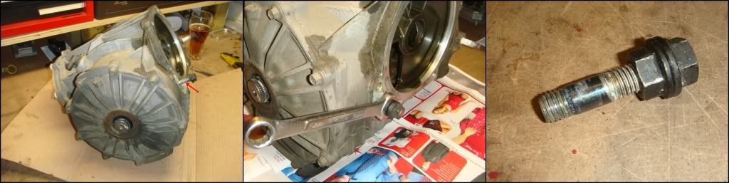
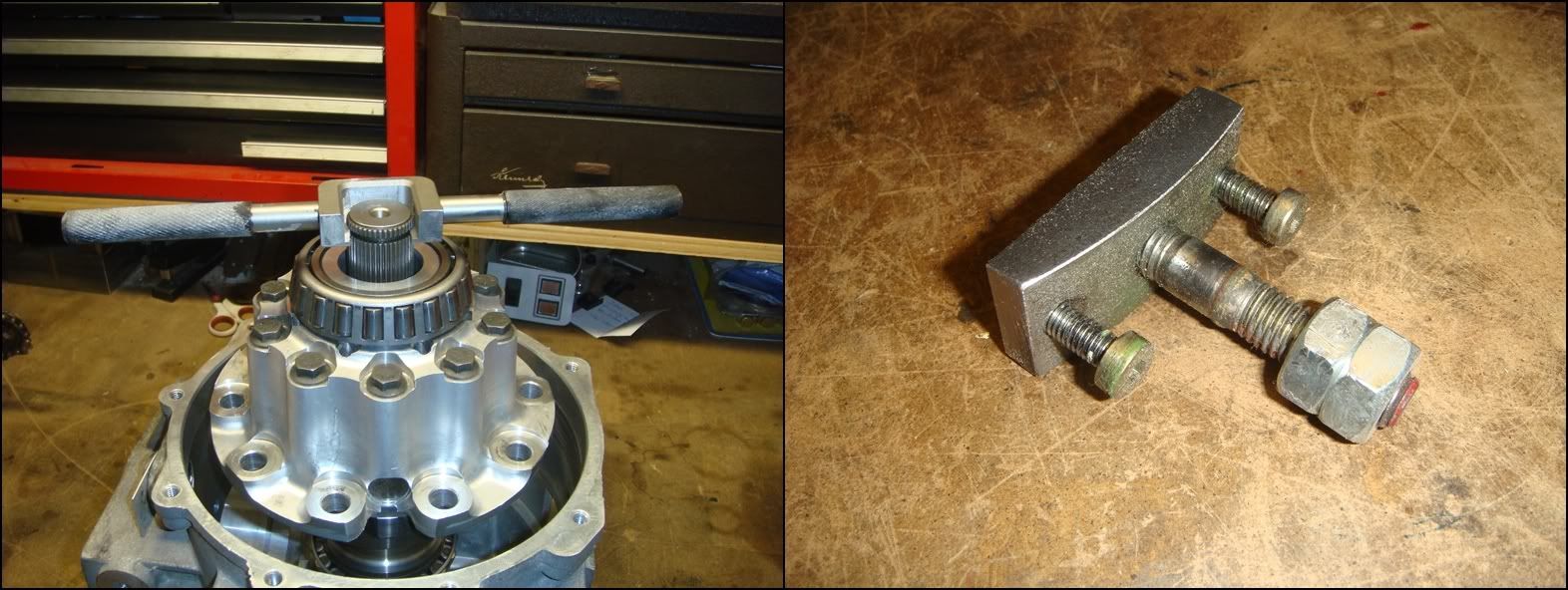
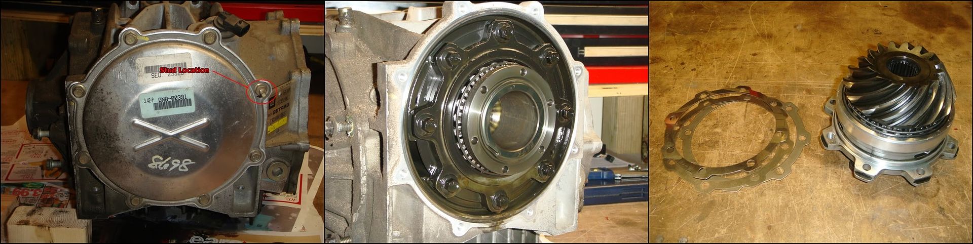
The tear-down starts here. The stud pointed out by the arrow in the first picture has to be removed. There are two studs screwed into the case where it bolts to the tranny...this is the one on the passenger side. The other one can stay put. Don't use Vice Grips! You'll chew up the stud. A better way to do this is to thread two nuts onto the stud and tighten them into each other. By turning on the inner nut, you should have no trouble spinning the stud out. You may as well leave the nuts on the stud as you'll use them to re-install the stud when you're done.
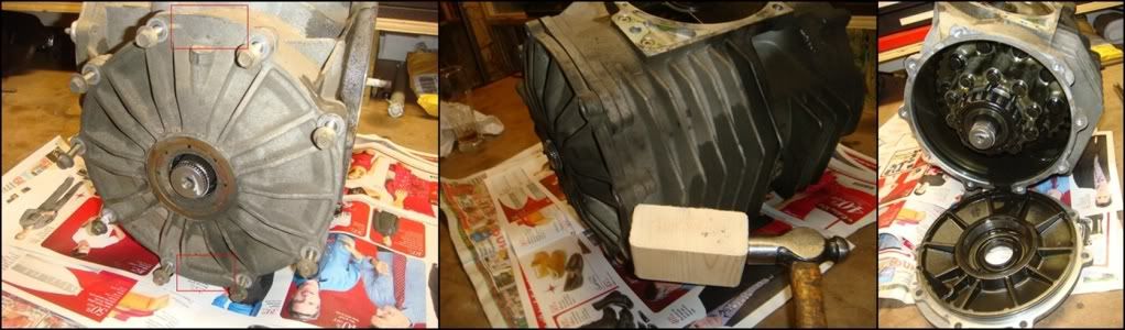
Now the RH cover can be taken off. Remove the nine 8mm bolts holding it to the case. The red outlines in the first pic show two webbed areas cast into the cover that can be tapped against to pop the cover free. Make sure that you drained the oil before this cover is removed, or you�re in for a big surprise�
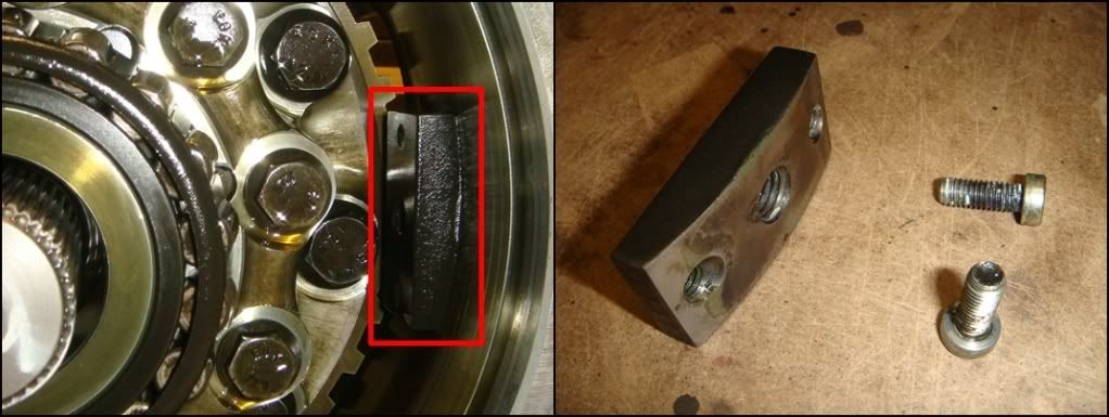
This block is what the stud screwed into. It adds reinforcement to the stud mounting. Before the differential carrier can be pulled out, this block has to be removed. It�s held in position by two 6mm hex head screws from outside, one above and one below the stud. You�ll need a 4 mm Allen key to remove them. Take note of the orientation of the block...thick side up.
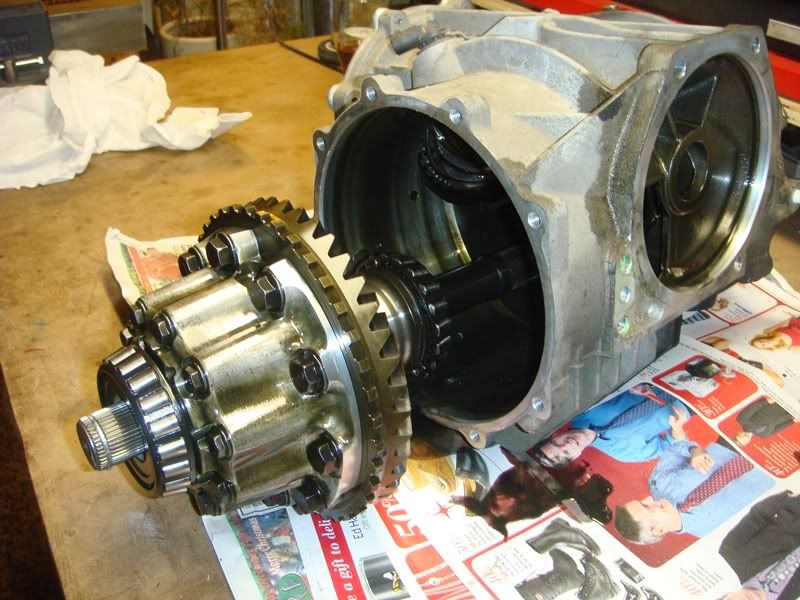
Once that block is removed, the carrier assembly can be pulled straight out of the case.
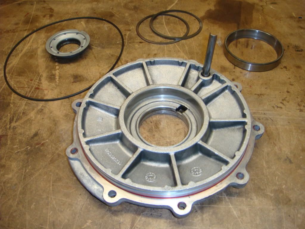
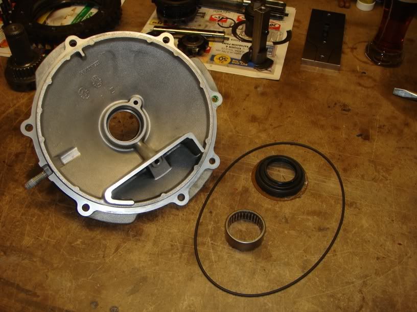
RH COVER DISASSEMBLY
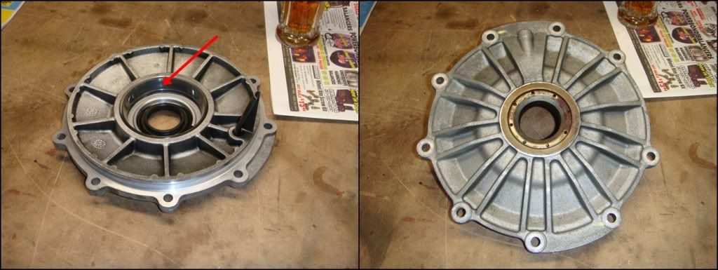
Here is a close-up of the RH cover. The first pic shows the bearing race, and the second shows the oil seal. Both of these can now be removed.
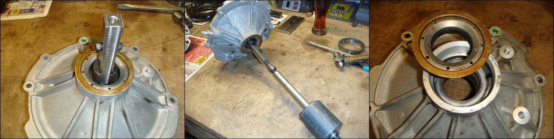
Pulling the right-side oil seal out is pretty straight forward. Either pry it out from outside with a screwdriver, use the hooked pry tool pictured in the tools section, or knock it out from the inside. This homemade tool will pop it out without damaging the seal or the bore, because I hate prying on $hit. These seals are brand new so I decided to re-use them, but if they're well used...throw them out. They have a well known history of leaking, and they don�t cost much.
The bearing race is next. Using J-42194 or similar, insert the tool into the race so that it "hooks" underneath the race. My homemade tool is installed in three pieces; the two outer round pieces hook under the race, then the third middle piece comes in and holds everything together. The shims between the race and the case have a slightly smaller ID than the race, creating a small gap. That's what these tools are designed to hook against. Don�t press these races back in without some shim behind them�they�ll push in flush with the bottom of the bore, and you will lose your mind trying to get them out again. Once the tool is in position, flip the cover over and lay it down in your press. I sat it down on a couple of 2x4s so the soft aluminum wouldn�t get bunged up. Just bring the press down into the opening and press against the tool until the race/shims fall out the bottom.
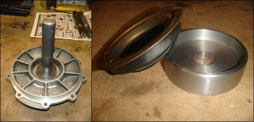
Here, the first pic shows the race in its bore, about to pop out. The second pic shows the race with the shims that were behind it.
This is what the RH cover looks like completely disassembled. I'd toss the seals, but definitely don't lose the shims. The sizes may be handy when you set up the new gears and/or bearings. If you are re-using the bearings, don't mix this race up with the one on the other side. The outer cones/inner races wear in together and should be left together as a matched pair.
LH COVER DISASSEMBLY
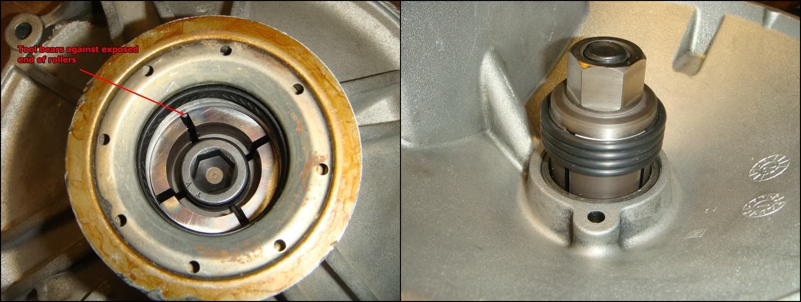
Removing the needle bearing is a bit tricky simply because there�s not very much to grab onto. The bearing bottoms out in its bore in such a way that the bottom of the bearing�s housing is completely inaccessible. The only way to get it out is to push against the ends of the rollers themselves, which only stick out by 2 or 3 kunt hairs. J-29369-2 is designed to be inserted into the bearing from the inside side of the cover, and then expanded out until it hooks on to as much of the roller as possible. A slide hammer is then connected to it, and the bearing pulled out. This alternate version works pretty much the same way, only instead of using a slide hammer, it use the press to push the bearing free. The first pic shows the tool expanded into position, looking in from the outside of the cover. The arrow shows what it�s actually trying to grasp. The yellowish ring along the outside is the oil seal, which gets pulled out next. The second pic shows the tool in position from the other side.
Once the bearing starts to move down, you can reset the tool to get a better grip on the now exposed backside of the bearing. That will give you a ton more grip. With all that said, take a close look at your bearing before you decide to remove it�your best bet may be to just leave it alone.
The oil seal can be removed next. The easiest way to do this is to use the hooked prying tool shown in the tool section. It will pull the seal out in about 5 seconds flat. I made the tool above for two reasons. It will pull the seal without destroying it; which is good if they are in new/almost new condition and can be re-used. If they happen have 5000miles on them then of course they can be reused...if they�re high mileage, throw them out for sure! This tool also avoids any possibility of damaging the delicate seal bore while prying the seal out. However, the seals come with a soft rubber coating on the OD to seal up any possible bore damage that might be done while prying.
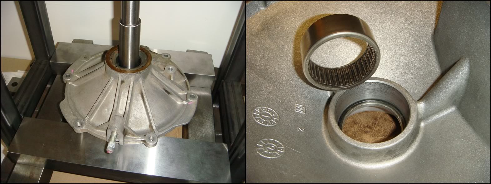
Here is the driver�s side cover stripped down nekid. If the diff hasn�t been touched in a more than a decade, I would consider replacing both the o-ring and axle seal. If you pried the axle seal out, also replace it. If you really have no money, you can probably reuse the o-ring. Especially so if you use a little aviation sealant on the flanges as well. The roller bearing needs to be looked at. Look for pits or gouges on the rollers. Unlikely, but also look for any signs of tan/brown discoloration, indicating burntness. If no damage is evident, you should have just left it in. By the look of things, this bearing has a pretty easy life; That small hole supplies a stream of oil to lubricate it while it helps keep the left CV joint from shaking due to the extra length of the output shaft.
MAIN CASE DISASSMBLY
With the covers out of the way, the case is next. The only thing to remove here is the LH bearing race and shims. Just like the other side, J-42194 is hooked under the race, and then pressed on to push everything out. If you like, you can stick your hand in thru the pinion opening to catch everything.
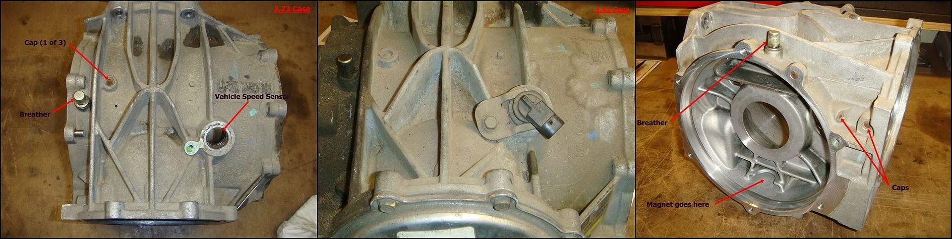
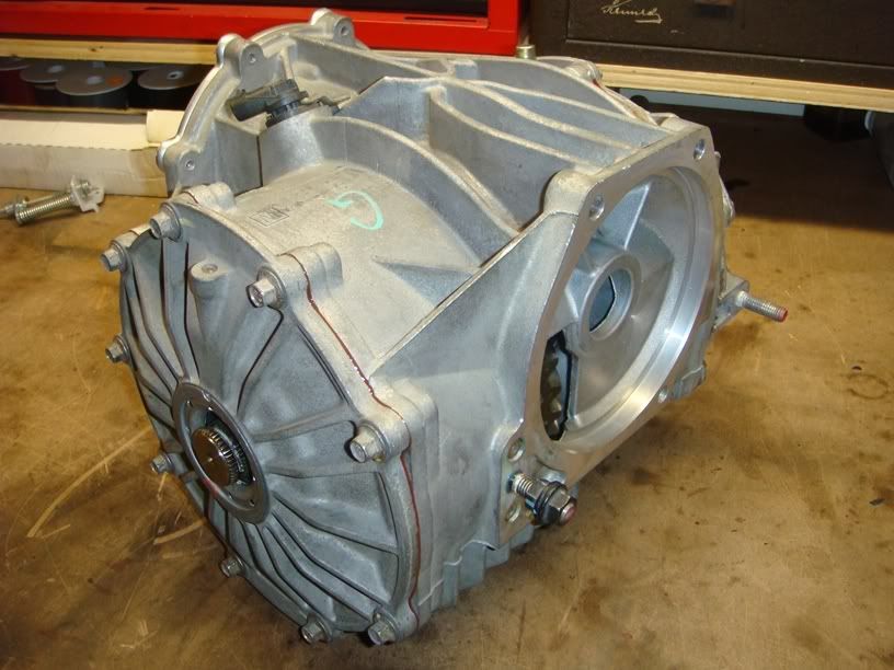
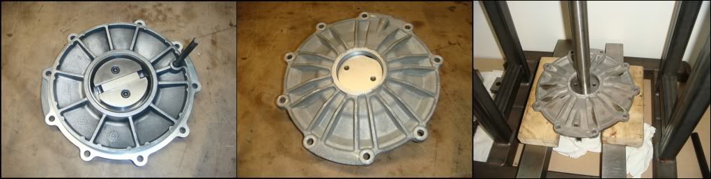
I have a bead blaster at work so� I had to strip the remaining stuff off the case to prevent damage during the cleaning process, including the vehicle speed sensor on top and the drain/fill plugs. The case has three capped holes in it: one on top, and two by the pinion bore. These were used during the manufacturing process to give drills access to the inside of the case to cut lube holes for the bearings. Unless they're leaking, I'd definitely leave them alone. Also, slide the magnet out and clean it. The stuff it's covered in will be in your finger pores for a week, so I'd use gloves or a rag for this. Please note that 2-series cases (first pic) have the vehicle speed sensor mounted further to the passenger side of the case than 3-series cases do (second pic). This is to compensate for the different ring gear locations between the two. You may run a 2-series carrier in a 3-series case (or vice-versa), but if you do, your speedo will not work correctly.
Here's a close-up of the case breather. It vents excess pressure developed inside the differential so the seals can work properly.
CARRIER DISSASSEMBLY
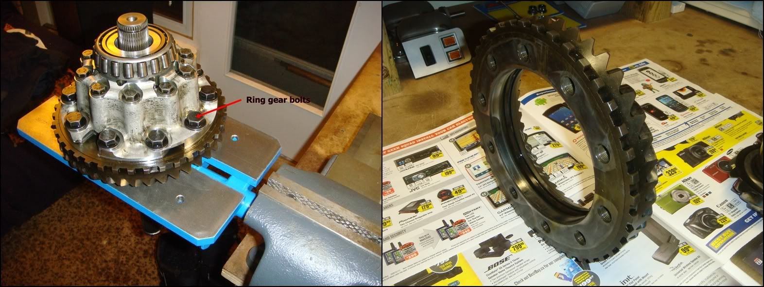
If you�re planning on changing your gears out for a different ratio, begin disassembling the carrier by removing the ring gear. You�ll also have to pull the ring off no matter what if you�re working on a 2 series carrier, as the different gear position covers the hole through which the cross shaft will later be removed. If you look closely at the ring gear pic above (2.73), you can see a shadow of this hole on the inside diameter of the gear. On 3-series carriers the cross shaft can be removed with the gear in place, so if the ratio is being left alone�leave the gear in place and skip to the next step. To get the ring off, remove the larger set of ten bolts running along the outside of the housing. This is where the holding fixture, J-42173, really comes in handy. The four prongs on the fixture lock into grooves in the cast iron half of the carrier, keeping it from turning. Otherwise, you�ll have to clamp the long output shaft in your vice, and put a second wrench on one of the upper bolts to keep the assembly from turning. Once the bolts are out, the ring gear won�t just fall off�stand it up on your work bench and tap it down along the outside with something soft like a piece of brass or copper until it pops loose. Leave a couple of screws lightly threaded to catch the gear when it pops loose. One thing I would definitely recommend if you do remove a ring gear you plan on reusing is marking the location of the gear relative to the housing so it can be reassembled exactly as it came off. If the gear or carrier housing has excess run-out, it will tend to wear-in unevenly. In this case, clocking it differently on the housing when you put it back together will result in an uneven mesh pattern, and make bluing-in the gears really frustrating. The backlash and mesh will wobble back and forth with the gear. If you forget to mark it, you still have a 50/50 chance if orienting it properly by looking at the shadow of the housing on the gear.
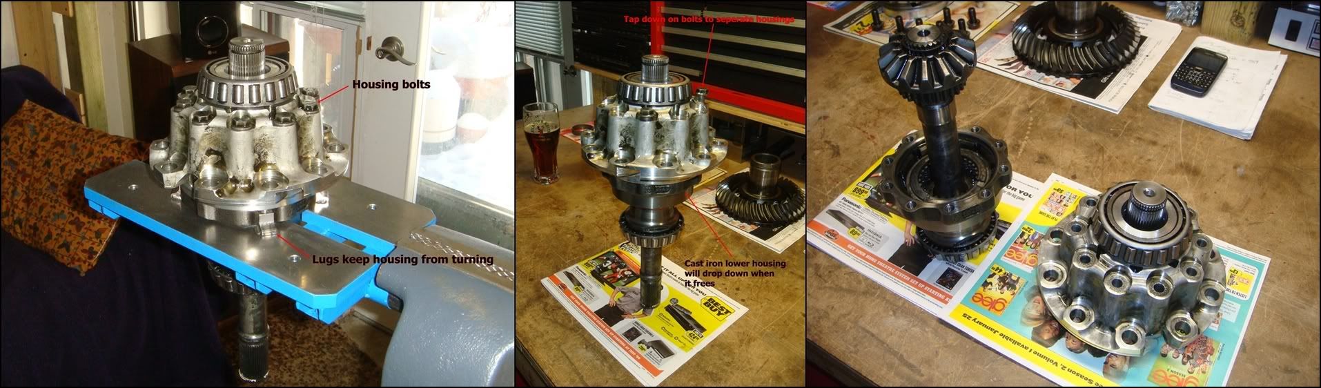
The next step is to separate the carrier case. The LH side is made from cast iron, while the larger RH side is aluminum. Place the carrier assembly back onto the holding fixture and loosen the housing bolts. Remove all but three of these bolts, leaving the remaining threaded in with about 3/8� sticking out. Stand it back up on the bench and gently tap down on the three screws until the lower half drops free. These remaining screws will then catch it before it flattens your hand.
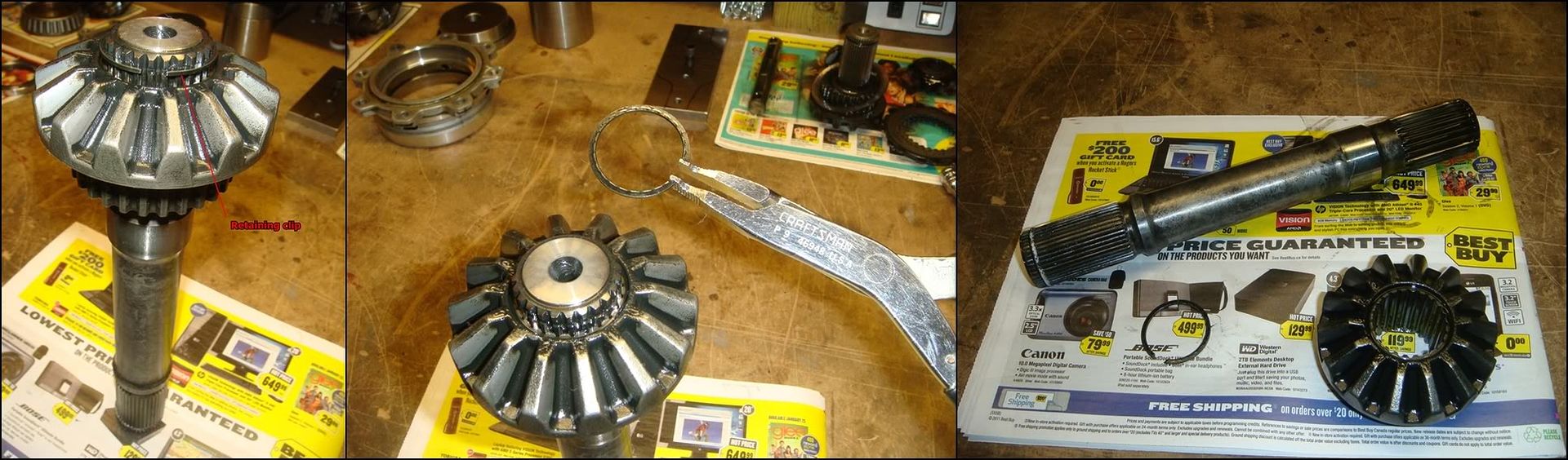
If you plan on replacing the LH output shaft with a stronger one, remove the retaining rings on both ends. I bought these pliers at Sears years ago, and they are perfect for this. A sharp awl or scriber will get em out as well. Once the clips are off, the side gear just slides right off. If you plan on reusing this shaft, skip this.
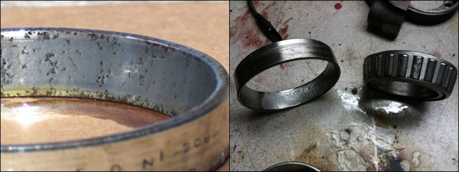
At this point, you must decide whether you are going to replace any of the bearings�so take a good look at them. If the differential was making a grinding or roaring type noise which varied with the speed of the car, the bearings may be the culprit. Noises can be pretty hard to diagnose if you�re not an expert; what sounds like bearings might actually be caused by the gears. Inspect the bearings closely (i.e. every single roller, cage and race) to eliminate them as a possible source of trouble later. And just because your rear end was quiet doesn�t mean it�s not in the early stages of bearing damage. The photos above show a few examples of BAD bearings. If the races show any signs of pitting or deep gouging, replace them. Same goes for the rollers themselves; inspect for pitting, scoring, grooving, etc. Inspect the cages which keep the rollers in place for signs of damage such as bending or cracking. Also inspect the rollers and races for heat discoloration. From the manual: �Heat discoloration ranges from a faint yellow to a dark blue color. The discoloration may result from an overload or improper lubrication. Excessive heat causes a softening of the rollers and races. Bearings or races with sign of heat discoloration must be replaced. The photos above were not taken by me, but are still good pictures of bad differential bearings.
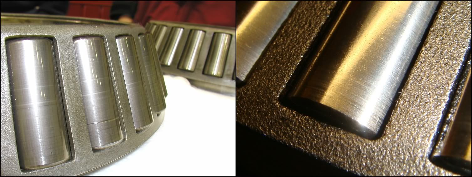
These pictures show bearings which are perfectly fine to reuse. Slight scoring like this is ok. I have yet to see a bearing that didn�t have at least a few lines on the rollers like this. As long as the rollers are still smooth and have no pick-up or galling, they�re most likely good to go.
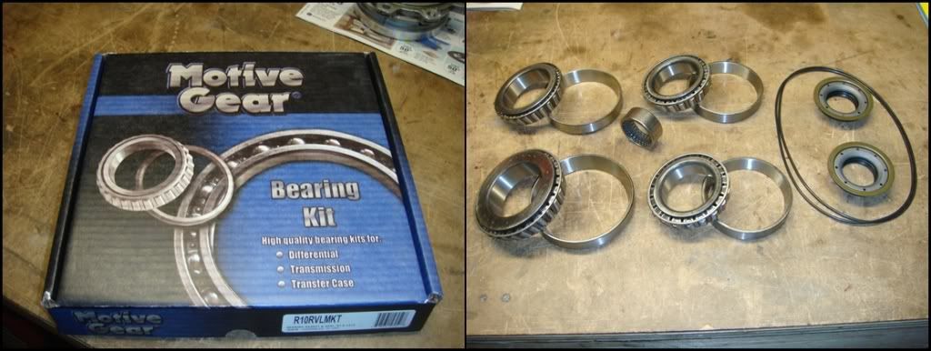
If new bearings are needed, this is one option. Motive sells a bearing kit, R10RVLMKT, which includes a full set of replacement Timken bearings. It also contains the side cover o-rings and oil seals. This kit has one HUGE problem with it. The pinion bearings in this differential are preloaded with a select-fit spacer and, to my knowledge, GM does not service this part anymore. They used to carry a range of spacers, but discontinued them. GM now requires us to purchase the entire pre-set assembly (bearings, housing, and spacer). I�m not sure how Motive thinks we are supposed set the proper preload without available spacers. You might get lucky with the original spacer, but what if the preload is out? Making your own is certainly a possibility, as is grinding a factory spacer down if it�s too wide. But unless you have the right equipment and skills, you�re pretty much stuck buying what GM sells (~$500). That�s why I�d steer away from this kit; the two pinion bearings on the left are gonna be hard to set up properly. To my knowledge, GM doesn�t service the side bearings either; they do however sell the needle roller for the LH cover. This leaves us with one more option for the side bearings: buy the bearings separately. They are all standard size bearings and can be ordered from any bearing supply house. I�ve included all the Timken bearing part numbers at the bottom for anyone who needs to do it like this.
If you need to replace this one, disassembly of the cast iron half of the case is finished with the removal of the bearing. If you are going to re-use this bearing, skip this step. There is no reason to remove it if it�s ok, and you might actually do more harm than good. My experience with this particular differential was that these bearings are on REALLY tight. My 9 Ton press couldn�t do it on its own� I was just waiting for the holding tool to crack. In a case like this, heat is your friend. Specifically, you can use a small propane torch to heat the inner race of the bearing to expand it a little. Try hard not to heat the iron housing that the bearing is pressed around. If everything expands together, you won�t get as much loosening action. Clamp J-42159 around the bearing as shown and use J-42162 to press the case down and out.
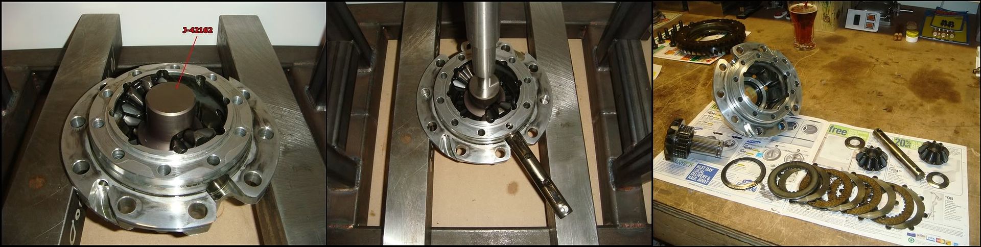
Now on to the aluminum half. Here, we need to pull the cross-shaft in order to remove the spider gears, RH side gear/output shaft and RH clutch pack. The clutch preload spring presses the side gear up hard against the spiders, keeping the shaft from just sliding out. J-42162 is used to push down against the side gear to relieve this pressure. Only a slight push is needed from the press to do this. Once the gear is pushed down, just use your finger to poke out the shaft.
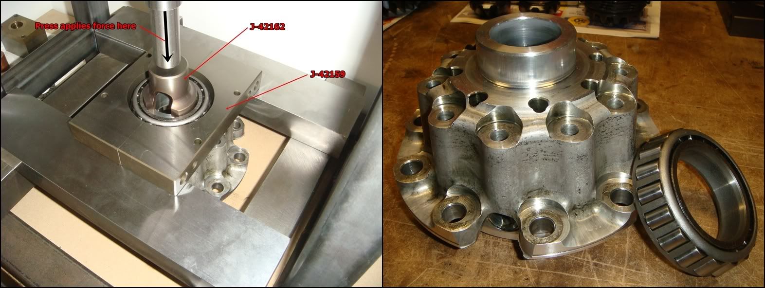
The last step in completely disassembling the carrier assembly is removing the RH bearing from the aluminum housing. As with the LH bearing, only remove if replacing with a new one. There is no other reason to do this, and the bearing may get damaged during the removal process. As with the left-side bearing, heat may certainly be needed to get this puppy off.
PINION DISASSEMBLY
The pinion assembly is under this cover. Remove the eight screws, taking note that one is not like the others. The screw with the stud sticking out of it is used to hold down a wiring harness and goes back in roughly the two o�clock position. The cover seals to the case with an o-ring, so it should pop off pretty easily. Once the cover is off, remove the 8 screws holding the pinion assembly to the case. The manual suggests heating the case with a heat gun to help the pinion housing slide out easier, but in my experience, it slides out easily without heating. Try and slide it out in one smooth motion so it doesn�t **** in the case. If it does, carefully tap it back in straight, and then try again. Once it�s out, you will find some shims that were sandwiched between the case and pinion housing. These control how the pinion meshes with the ring gear, and are important! Make sure you don�t lose any.
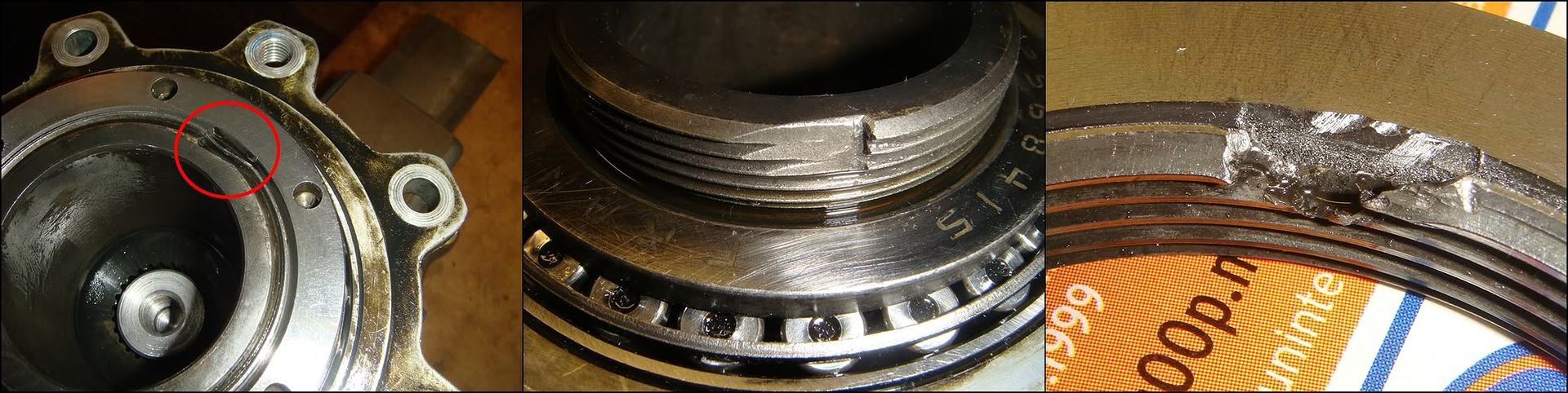
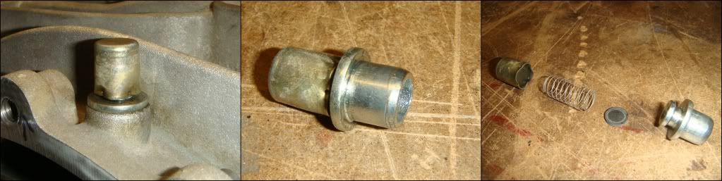
The next thing to disassemble is the pinion assembly. This is comprised of a pinion mounted on two tapered roller bearings with a spacer in between to control preload. The whole thing is held together by a special round nut which is torqued down super tight. The outer bearing races are pressed into an aluminum carrier, which holds it all together. The first step is to remove the nut, but before this can happen, the stake securing the nut to the pinion has to be cleared. The nut has a ring on it which gets staked into a groove in the pinion to help ensure the nut doesn't loosen off. This ring is about 3/32 thick, and doesn't bend easy. It's not that hard to make the stake, but for some reason, it is REALLY hard to bend it back out of the way. I�m sure the pros have a way of doing this quickly, but not me. Unless you clear it completely, the nut won't budge. I ended up cutting it away with a die grinder, being super careful not to grind into the pinion. Shown are close-ups of the staked-on nut, as well as the pinion and nut after they were separated. In my opinion, the nut is a throw away item, so don't worry about what it looks like after you get it off. I have spoken to builders that routinely reuse this nut� but for 30 bucks, it seems like false economy to me. What do you do if the damaged area of the nut lines up with the stake area on the new pinion? Loctite, I guess. Once the staked area is cleared, the nut can be cracked loose and spun off. A tip from me to you: do yourself a huge favor and use an impact gun for this. It will really help the nut break past any remaining staked thread. You will need to hold the pinion stationary using J-42164, and you will need J-42172 to actually loosen the nut. The nut doesn't have flats on it. Rather, it has 6 holes around the perimeter which J-42172 grabs onto to turn it.
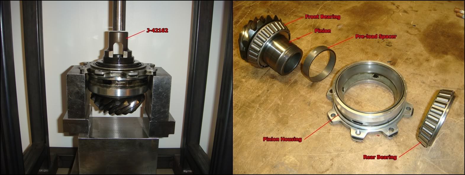
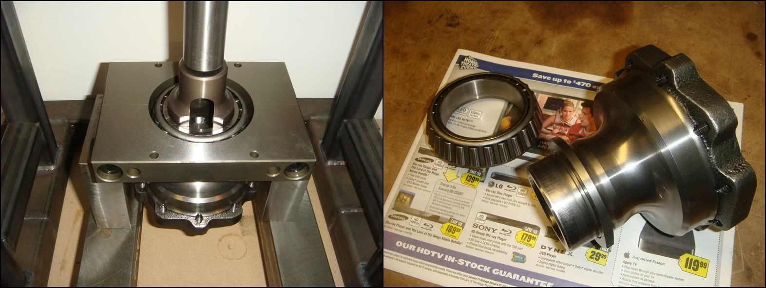
Once the nut is off, the rest of the disassembly goes quick and easy. The next step is to press the pinion out of the rear bearing. No special bearing holding tool is necessary, as the pinion housing does the job. Set the housing up in your press as shown and sit J-42162 against the threaded end of the pinion. Press down against J-42162 until the pinion is free of the rear bearing (top bearing in left photo above). Place a rag or something soft underneath to catch everything when it comes loose. Remove the rear bearing from the housing and put it aside with the preload spacer, which just slides off the pinion. This spacer is selectively chosen to produce the proper bearing preload with this particular housing and bearings. These parts must stay together.
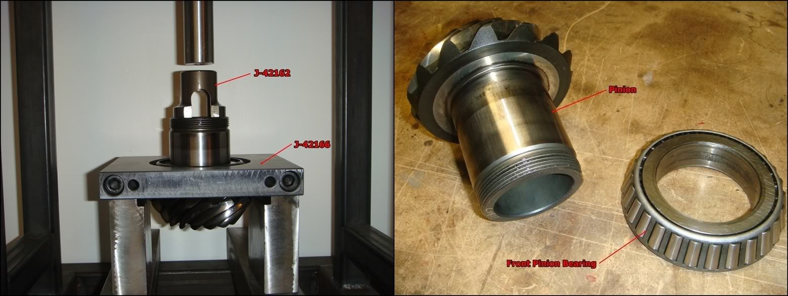
Front bearing removal: Clamp J-42166 around the front bearing and set this assembly up in your press something like this. Use J-42162 again to press the pinion out of the bearing.
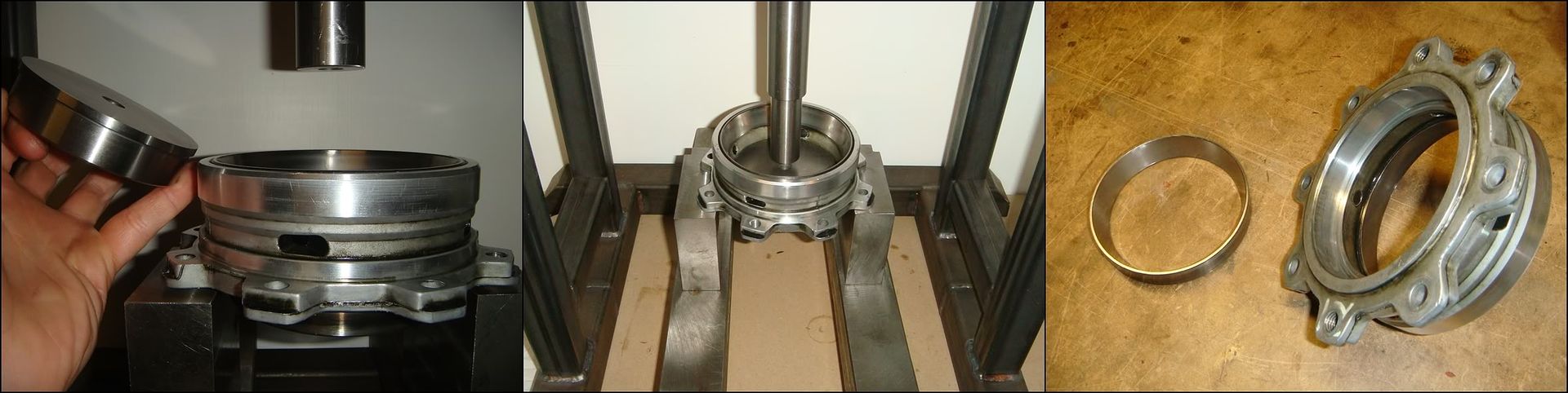
Removing the two bearing races from the aluminum housing will complete the disassembly of the pinion assembly. If the bearings are in good condition and will be reused, this step should definitely be skipped. Remove these races ONLY if the bearings will be replaced. The races are removed by supporting the housing in your press and hooking J-42194 under each race and pressing it out. Alternately, the smaller rear race can be pressed out with a simple bushing remover, as shown above.
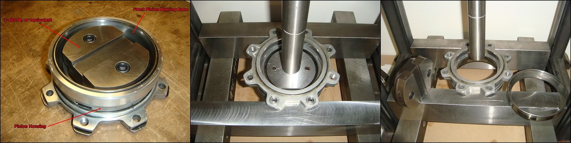
The larger front race will still need a dedicated removal tool, J-42194 or something similar. Using a bushing remover here is not possible because the OD of the front race is greater than the hole you have to insert the tool. The housing tapers down from front to back, requiring an adjustable type tool like the one in the photos above. Hook it under the race the same way you did with the side bearings, flip it over and place it in the press as shown. Support the housing by two ears on each side so it�s nice and stable.
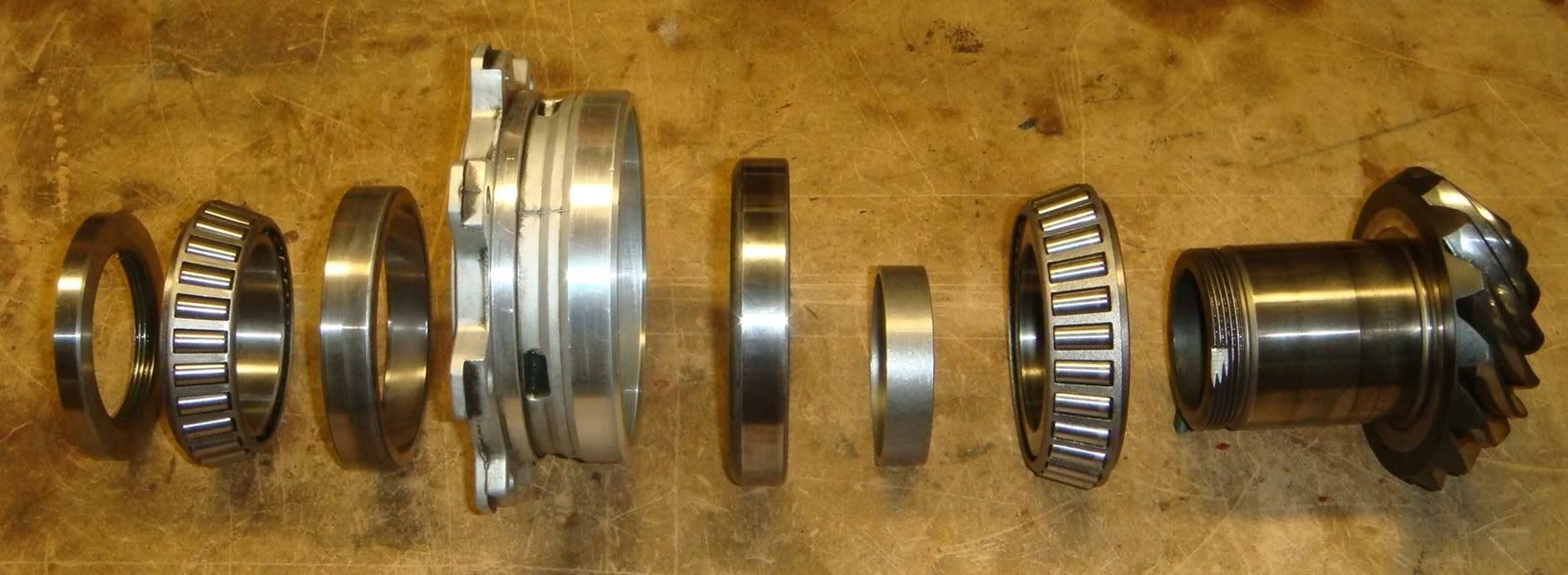
Here is an exploded view of the pinion assembly, held up by the power of happy thoughts. From left to right: pinion nut, rear bearing, rear bearing outer race, pinion housing, front bearing outer race, pre-load spacer, front bearing, pinion.
With that done, this differential is as disassembled as it�s going get. Just remember that yours probably won�t need to be taken apart this completely. Not to beat a dead horse, but if the pinion bearings are good, leave the outer races in place. Definitely also leave the left and right bearings pressed onto the carrier if they are in good shape. �If it aint broke�.� Never applied more that it does here. Also remember that if you DO decide to replace the pinion bearings separately (without replacing the whole unit as per GM�s recommendation), you are on your own as far as setting the preload. Unless you have a stash of various preload spacers, or know how to make your own, I�d avoid it altogether.
The following 4 users liked this post by Its_Go_Time:
11-20-2011, 02:18 PM
#4
Burning Brakes
Thread Starter
GM made the set-up of these gears a very scientific undertaking. If you take accurate measurements, make the appropriate calculations, and use the resulting shim sizes...the gears should mesh very well. Checking with marking compound is a good idea, but this technique will almost certainly get you super close.
This part of the project can be broken down into four separate steps:
1) Select LH shim stack to position the ring gear properly within the case left-right. (Setting Dimension "A", below)
2) Select shims to position the pinion assembly within the case fwd/aft for proper mesh.
3) Select RH shim stack to provide proper preload for both side bearings. (Setting Dimension "B")
4) Check backlash, and adjust the LH shim stack if necessary.
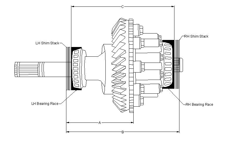
The differential carrier is mounted onto two tapered roller bearings. The races in which these bearings ride are pressed into bores machined into the case. On the RH side, the race is bored into the side cover. On the LH side, it�s bored directly into the main case. The LH and RH shim stacks pictured above slip into these bores before the races are pressed in. The difference between dimension B above and dimension 1 below is the side bearing preload, set by the RH shims. Because the LH shims control ring gear location and the RH shims are then added until the proper preload is obtained, the two shim stacks will more than likely be of different thickness. Don�t assume that they are the same!
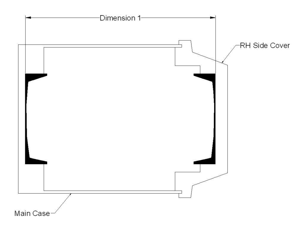
The first step is to position the ring gear L-R within the case (the only adjustment it has). The ring gear teeth are machined onto a blank which then bolts onto a machined surface on the differential carrier. The critical dimension here is where those teeth are cut with respect to the mounting surface. And, as always in manufacturing, there is a tolerance associated with it. The manual refers to it at a manufacturing variation, and it's the reason you can't just swap in new gears without adjusting (or at least checking) their position. There is also a tolerance associated with the location of the carrier mounting flange. The new gear will bolt-up in exactly the same place as the old, but the teeth will most certainly be in a slightly different location with respect to the mating pinion teeth. The A2 value marked on the ring gear by the manufacturer is the "magic number" which tells us exactly where those teeth are relative to the mounting flange.
LH Side Shim Selection
The selection of this shim stack involves measuring where the ring gear is located with respect to the pinion centerline. Manufacturing tolerances applied to the case, differential carrier, pinion, ring gear, and bearings all conspire to make this dimension an unknown unless it is actually measured. To make this measurement, you will need these special J tools: J-42168-2, J-42168-11, J-42168-7, and J-42168-13.
NOTE: Not all ring/pinions come with an A2 value engraved on them. The factory sets should all have both A1 and A2 values, but aftermarket gears may not. They should ALL have A1 though, which is needed to set pinion depth. If this applies to you, the following factory process for selecting the left hand side shims will not work. The alternate method will involve setting the pinion depth FIRST, then selecting LH shims that produce a backlash value between .0067� and .0082�. This will be a trial-and-error process. I recommend using the same LH shims that were used in your original set-up as a good random starting point. If the backlash is tight, add shim. If backlash is too loose, remove shim. Setting backlash properly is key to a quiet, happy rear end, so don�t get frustrated here and just say �good enough��a noisy rear after so much dicking around would really bite.
If, however, your gear-set has an A2 value, shim selection is a much more exact process�
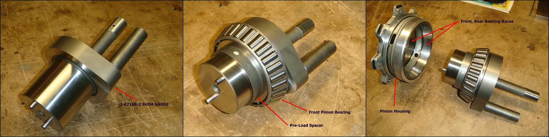
This is the first of two measurements made using J-42168-2. This is probably the most critical measuring tool used to build this differential. Along with J-42168-1, they are solely responsible for how the ring and pinion mesh�at least until we check it with high spot blue. This tool measures the fore-aft distance between the pinion locating flange and the centerline of the carrier. It also measures the L-R distance between the pinion centerline and the LH carrier bearing bore. These two measurements will tell us how much to shim the ring gear to the right, and how much to shim the pinion back to get a good mesh pattern on the gears. To use this tool, it must be assembled with bearings and spacer into the pinion housing, basically replacing the pinion in the assembly. The bearings are a smooth slip-fit onto J-42168-2, so assembly is a breeze. Slide the front bearing on first, followed by the preload spacer, and then install this assembly into the pinion housing. The pinion housing must have both outer races installed.
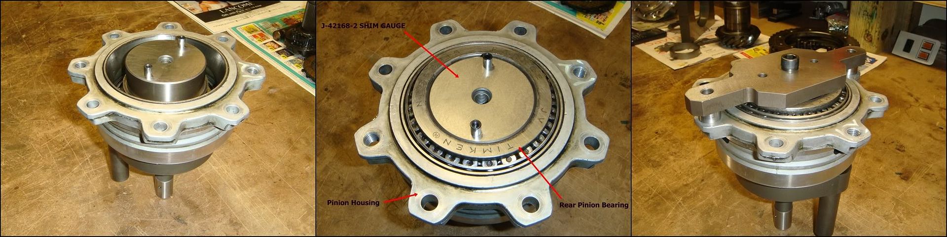
Flip it up on the work bench and slip the rear bearing into place. Then the clamp that holds it all together can be fitted. Lightly snug the center bolt to hold the assembly together. Make sure it�s tight enough to remove any play from the bearings. A little tighter is better than a little looser here. The homemade clamp-bar shown here orients J-42168-2 properly in the case by using two of the eight pinion housing screws. The factory tool allows the assembly to still turn somewhat; it is positioned properly by turning it until the lower probe rests against the web cast into the case (see below).
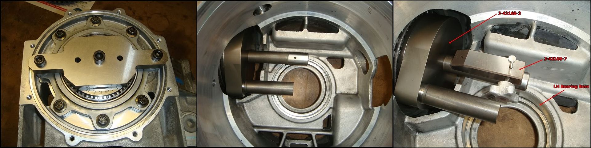
Now lower the completed assembly into the main case and torque all 8 screws to 18 lb ft. If these screws are not tightened properly, the measurement taken may not be accurate. The second pic shows how it should look from inside the case. The small hole in the upper probe should point directly down towards the bearing bore below. Now that J-42168-2 is in position we can finally begin taking measurements. The first measures the sideways position of the ring gear relative to the pinion. For this, we need to use J-42168-7, what GM refers to as a �depth gauge�. It�s simply used to �transfer� the distance from the top of the upper probe to the bottom of the bearing bore to the next tool shown below, where the actual measurement will take place. Position J-42168-7 by inserting the long gauge pin into the small hole in the probe, and then slide the whole thing down until it rests level against the probe.
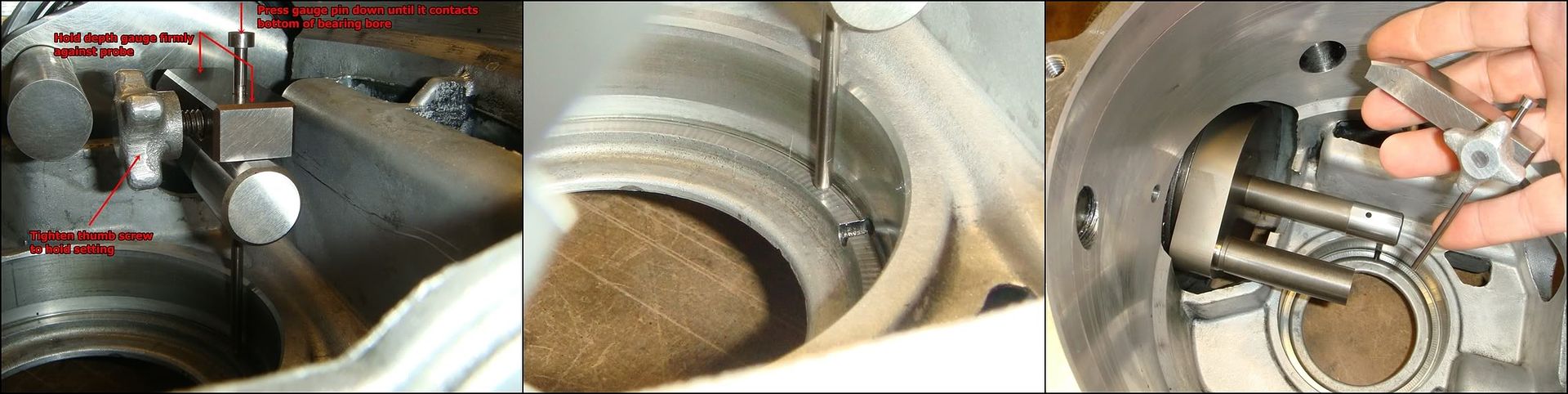
Loosen the thumb screw to allow the gauge pin to slide up/down. Press down lightly on the depth gauge to ensure it is sitting level with the probe. If it�s not level, the accuracy of your measurement will suffer. At the same time, press down lightly against the top of the pin so it contacts the bottom of the bearing bore. Once you�re satisfied that everything is level and touching properly, tighten the thumb screw to �lock in� the setting. Don�t tighten the crap out if it, or the end of the screw will sink right into the pin. The next time you use it, it will try to pick up the indentation and throw your measurement off. Gently slide the gauge straight up and out, obviously being careful not to disturb the setting.
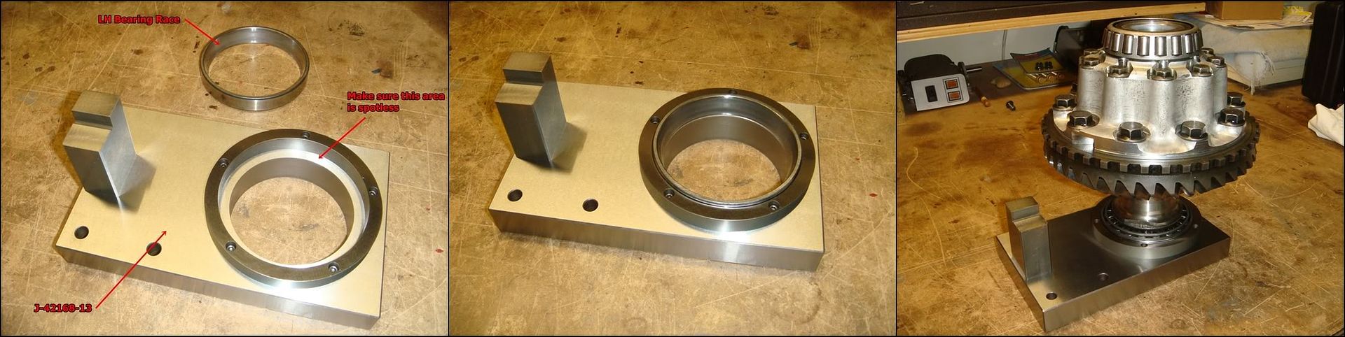
To get J-42168-13 ready, first wipe down the area shown above. Make sure it�s completely clean, and then drop the LH bearing race into place. Lower the carrier assembly onto the bearing race as shown. Turn it back and forth a few times to ensure the bearing is seated properly. The carrier shown above has its output shafts removed, but this can also be done with the shafts in place. If the shafts are present, clamp the gauge plate in a vice to allow the long LH shaft to poke out the bottom. Also check that the ring gear bolts and housing bolts are all torqued properly.
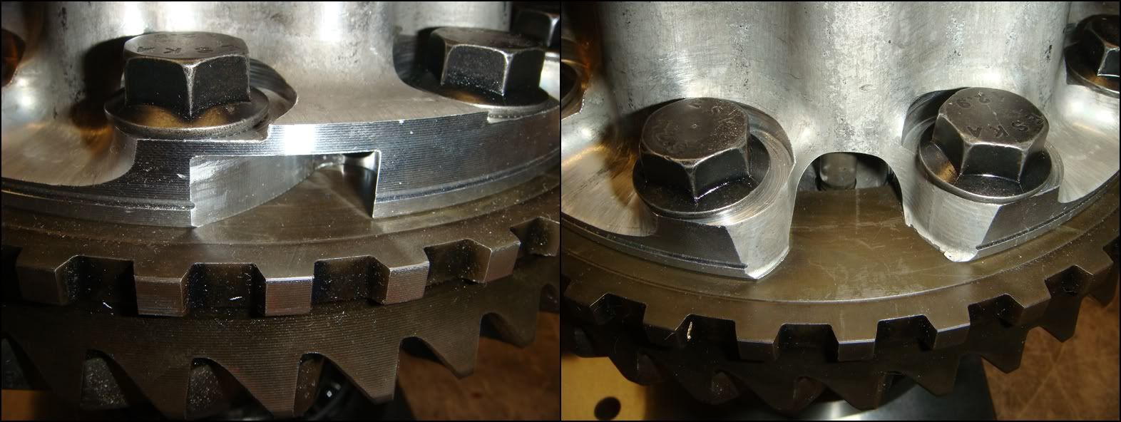
These two pics show where the depth-gauge (J-42168-7) attaches to the ring gear. The first photo shows where the factory tool goes. The tool is simply pushed in until it jams tight. There are two slots like this, spaced 180 degrees apart. These slots are identical on both 2 and 3 series carriers. The second pic shows where my homemade tool attaches. It simply lays flat on this surface, with the embedded magnet holding it firmly in position. This is actually part of the cross-shaft pin bore. The carrier shown is a 2 series; the 3 series looks slightly different.
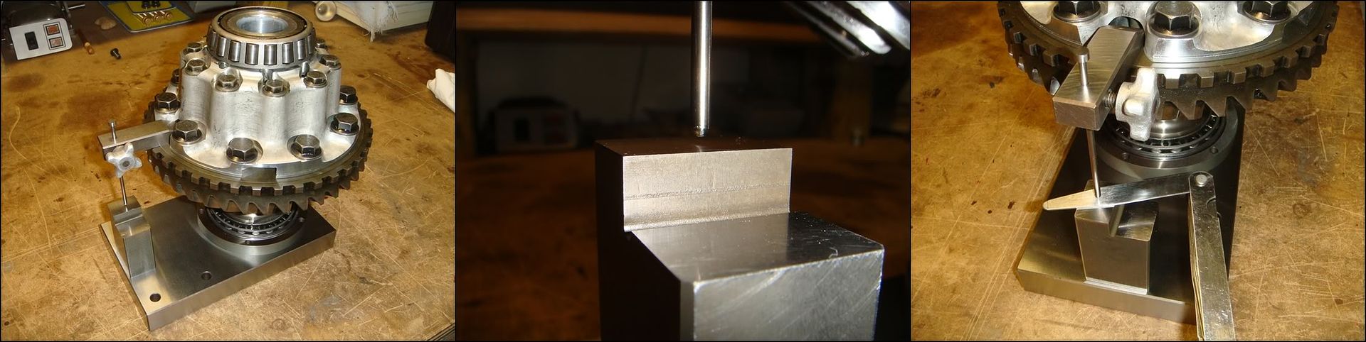
Set J-42168-7 into position and then rotate the carrier until the gauge pin is over the gauge block. The gauge block has two levels on it; use the upper level for 2 series carriers, and the lower for 3 (and 4) series. Feeler gauge the gap, and record this dimension as C1. Make absolutely sure that the depth-gauge remains flat and parallel with the ring gear while the gap is being measured. I recommend putting slight finger pressure on it to keep it flush with the gear. Try not to use more than two feeler gauges at once as the more gauges in the stack, the less accurate the measurement becomes. I usually free the blades from the holder so I can pick and choose the right sizes easier.
Now for the first round of calculations. The first step is to subtract C1 from a C nominal value of 5mm (.0197 in). Record this value as C2.
C2 = .197� � C1
In this particular case, C1 measured in at .040�, so C2 becomes .157�.
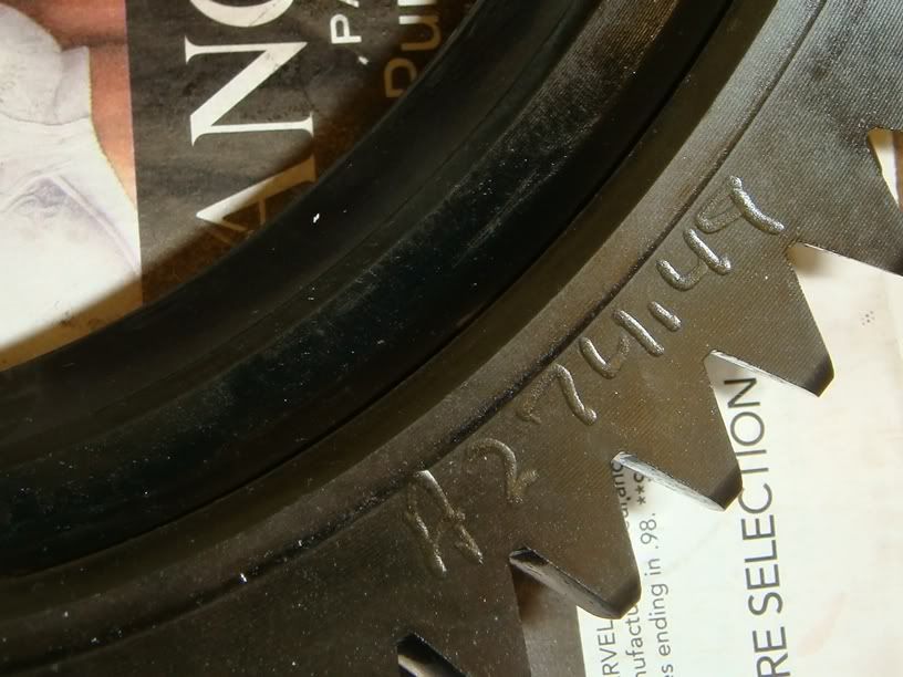
Locate the A2 value engraved on the side of the ring gear. From the manual: �The A2 value is a manufacturing variation between the ring gear and the pinion. The A2 value may be higher, lower, or equal to 65.5mm (2.58 in) for 3.15 and 3.42 ratio differentials, or 74.5mm (2.93 in) for 2.73 ratio differentials, nominal value. When subtracting the D nominal value from the A2 value, the C3 calculation may compute to a positive, negative, or zero total.� In other words:
C3 = A2 � 74.5mm for 2 series carriers,
Or
C3 = A2 � 65.5mm for 3 (and 4) series carriers.
In this case A2 is 74.49mm for a 2.73 carrier, so C3 calculates to -.01mm
Because C1 will most likely be measured with Imperial (inch) feeler gauges, C2 will also be in inches. C3 will be a value expressed in millimeters, because the ring gear A2 value is given in mm. A conversion needs to be made before the two can be added. Personally, I prefer to work in inches�so I simply convert C3 into inches by dividing it by 25.4.
C3 (inches) = C3 (mm) / 25.4
In this case, C3 becomes -.0004�.
And finally:
LH differential bearing Shim Thickness = C2 + C3
For this example, the final shim stack worked out to .1566�.
From the manual: �select shims equal to the calculated value. It may be necessary to round the shim or shims total to obtain the proper shim sizes. If the shim thickness calculation is past the midpoint value, round the value to the next decimal value.�
GM produces side shims in 12 different sizes:
1.00mm 0.0393 in
1.25mm 0.0492 in
1.30mm 0.0511 in
1.40mm 0.0551 in
1.50mm 0.0590 in
1.60mm 0.0629 in
1.70mm 0.0669 in
1.80mm 0.0708 in
1.90mm 0.0748 in
2.00mm 0.0787 in
2.10mm 0.0826 in
2.20mm 0.0866 in
From the table above,
0.0669 and 0.0866 forms a stack .1535
0.0708 and 0.0866 forms a stack .1574
with .1555 as the midpoint between the two.
Because our calculated thickness of 0.1566 is past the midpoint, I will use 0.0708 and 0.0866 as the final shims.
Note that the shims go up in increments of 0.1mm, except for the second one (1.25mm) which has a 0.05 increment. That makes this one useful for fine tuning the stack thickness. In the case above, if we used the THREE shims: 0.0039, 0.0492, and 0.0669, we would produce an overall thickness of 0.1554, which is right in the middle of the two stacks above. The midpoint between this stack and the next stack up (.1574) is 0.1564, which is pretty much the calculated thickness we need. This means that we could use either one. I would much rather use two shims than three, so I�ll go with the two shim stack of 0.1574.
Pinion Shim Selection
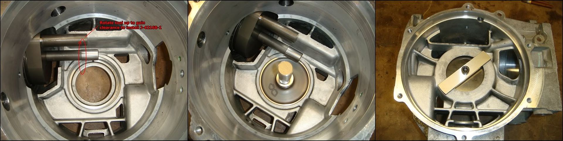
The next step is to measure where the pinion is fore/aft with respect to the ring gear centerline. As mentioned above, J-42168-2 is also used to accomplish this. However, this time it is used in conjunction with J-42168-1. J-42168-1 simply extends the centerline of the carrier bearings out under J-42168-2. The first step is to rotate J-42168-2 so that there is enough room to insert J-42168-1 into the bearing bore. In my case, I had to remove the two screws locating the tool to the case, allowing it to rotate on the pinion bearings. If using the factory tools, the tool can simply be spun out of the way. Once there is enough room, slide J-42168-1 into position in the LH bearing bore. Clamp it into position with holding strap J-42168-9 from the other side.
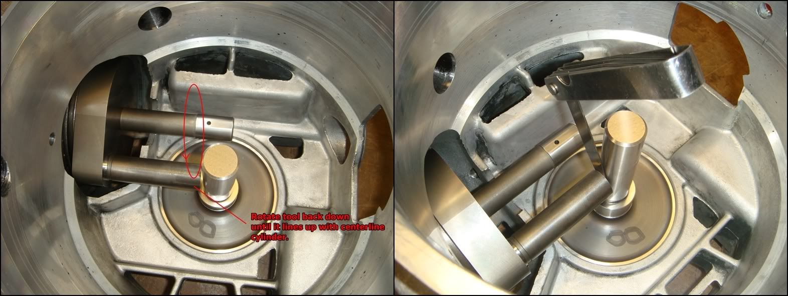
Once the centerline cylinder is in position, rotate J-42168-2 back down until the shorter probe lines up with it. With these homemade versions, I just bolted down the alignment strap to lock J-42168-2 down into this position. The factory tool simply bottoms out against a web cast into the case, which keeps it from rotating any more. Now, feeler gauge the gap between the two. As mentioned above, try and use no more than two feelers together at once for better accuracy. Write this value down, referred to as B1 in the manual.
Now come the second round of calculations, used to come up with the pinion housing shim thickness. The first is a simple modifier to B1, measured above. These tools are designed with a nominal gap of 5mm(.197�), which ensures that no matter how the manufacturing tolerances of the various elements(case machining, pinion bore machining, pinion housing machining, bearing thickness, pinion machining�etc) add up, there will ALWAYS be a gap between the two tools. If the feeler dimension measured here were .197�, it would indicate that the tolerances for all these various elements added to give the exact designed position of the pinion within the case. Any deviation will indicate how far the position of the pinion is out of tolerance. The value measured above is simply subtracted from this nominal value, giving us B2
B2 = .197� � B1
In this case, B1 measured in at 0.158 so B2 works out to 0.039
The next step is to read the A1 value engraved into the ring gear. In the example below, A1 = 103.00mm
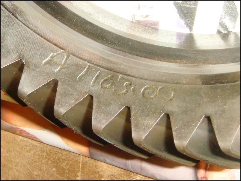
From the manual: �The A1 value is a manufacturing variation between the ring gear and pinion. The A1 value may be higher, lower, or equal to 103.00mm (4.055�) nominal value. When subtracting the A nominal value from the A1 value, the B3 calculation may compute to a positive, zero, or negative total�. In other words, B3 = A1 � A, where A is a nominal value of 103.00mm. As above, any deviation from the nominal dimension (103.00mm) will indicate the machining error in the gear set. In this case, the pinion was machined **** on, with B3 (error) computing to 0.
B3 (mm) = A1 � 103.00
In this case, B3 works out to 0
Please note, because B1 will most likely be measured with Imperial (inch) feeler gauges, B2 will also be in inches. B3 will be a value expressed in millimeters, because the ring gear A1 value is given in mm. A conversion needs to be made before the two can be added. Personally, I prefer to work in inches�so I simply convert B3 into inches by dividing it by 25.4.
B3 (inches) = B3 (mm) / 25.4
0 inches equals 0mm�
So finally:
Pinion Shim Thickness = B2 + B3
Pinion shim thickness = 0 .039 + 0 = 0.039.
Again, from the manual: �Select shims equal to the calculated value. It may be necessary to round the shim or shims total to obtain the proper size shim pack. If the shim thickness calculation is past the midpoint value, round the number higher to the next decimal value.�
GM produces pinion shims in 5 different thicknesses:
0.20mm 0.0078�
0.25mm 0.0098�
0.30mm 0.0118�
0.50mm 0.0196�
1.0mm 0.0393�
The 1.0mm shim matches the calculated thickness almost perfectly, so that�s the one we will use. Otherwise, use the same process as with the side shims to select the best possible combination.
RH Side Shim Selection
This last shim sets the �axial preload� on the two carrier bearings. When the carrier is installed back into the case and the RH cover torqued down, the two bearings are pressed towards each other with a slight force called preload. Setting this properly will help ensure maximum bearing life and quiet operation. If preload is nonexistent and the bearings have slop in them, the mesh between the gears will be inconsistent and they will be noisy. If preload is too high, the bearings will overheat and fail prematurely. This measurement has to wait until the carrier has been fully reassembled, so it�s a little out of order here. Once you reach the point where the LH shims/race are pressed in and the carrier is back together with shafts, clutches, etc, skip back to this section to measure the preload and select the RH shims.
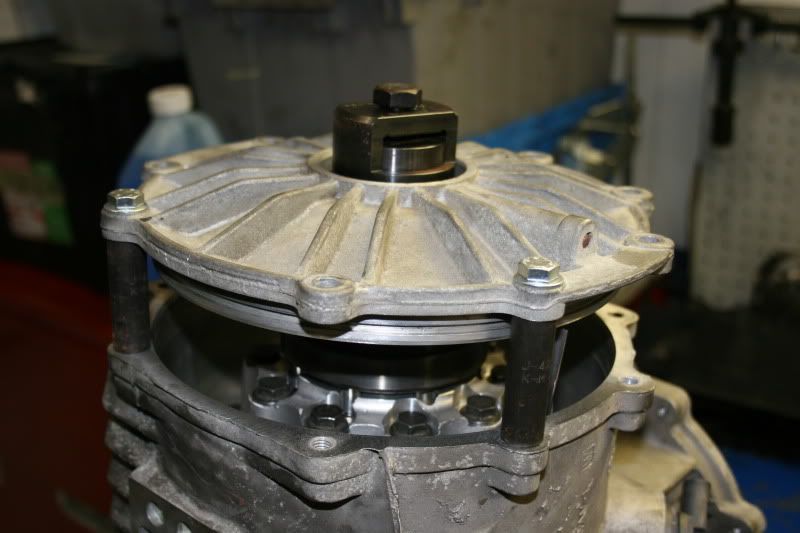
If you are using the factory tool for this, the procedure is very easy. Mount the case onto the holding fixture with the RH cover flange pointing up. Slide the carrier down into the case and make sure the bearing seats properly into the race by turning the carrier back and forth a few times. Now lay the RH bearing race down onto the bearing and seat it in the same way. Lay the "side bearing shim selector" tool, J-42168-15 onto the race, and lower the RH cover down over it so it pokes out the top. You'll notice that you won't be able to lower the cover on flush with the case...that's what the spacers are for. Using the three spacers and the longer bolts provided with them, bolt the cover to the case. All that's left to do is to feeler gauge the measuring gap in the tool. This dimension is the RH shim thickness. I found this picture on the forum some time ago, but I'm pretty sure credit for it goes to Rick@RKT56. Rick is a fantastic source of info regarding these differentials and is a great person to turn to for help.
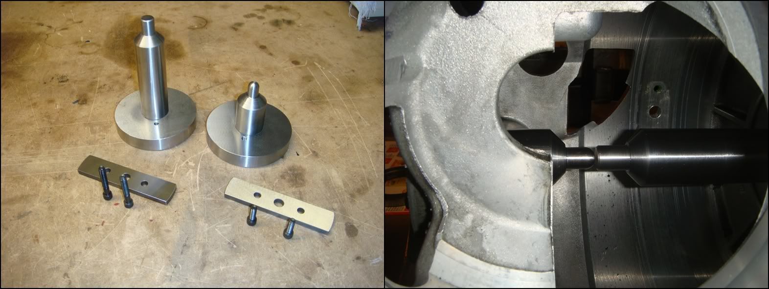
In the absence of the factory tool, the bearings can still be set accurately. By measuring the distance inside the case between the two lands that support the bearing races, and measuring across the two races as they sit on the installed carrier bearings, the preload can be calculated. To measure the distance inside the case, I made these two gauges. One gauge fits into each bore, and is held in place with a strap from the other side. When the side cover is fitted back onto the main case, the gauges will come within .010-.030 of each other. Knowing the exact length of each gauge, plus the feeler dimension between them, the overall width can be calculated. The LH gauge was made to a finished length of 3.025, and the RH gauge to 5.406. In this particular case, a .020 feeler was the thickest that would slide between the two, giving an overall width of 8.451.
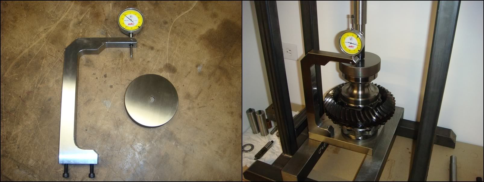
The second measurement across the bearings races on the carrier were made using an attachment to the gauge plate J-42168-13. It measures the overall width of the rotating assembly that fits into the case bearing bores. The differential carrier, with both bearings and outer races in place, is placed onto the gauge plate. The round puck is then placed on top and the hydraulic press adds a little preload (through a spring) to make sure the bearings are seated properly. The dial indicator then gives the overall width of the entire assembly. This dimension, plus the RH and LH shim stacks must be GREATER than the case width, measured above, to achieve preload on the bearings. This carrier measured in at 8.451, giving a total preload of exactly zero. This �line-to-line�, no pre-load/ no clearance fit generally gives the highest bearing life in most taper-roller bearing applications, but is often times no good in gear boxes�especially hypoid ring and pinions. By adding pre-load to the bearings, deflections of the gears can be greatly reduced, maintaining proper gear mesh, and quiet operation. As bearings wear-in, their pre-load drops�used bearings can sometimes be set up with as little as half the preload of new ones to take this into account. The case also slowly stress relieves itself as it continually heats/cools, resulting in an additional loss in pre-load. In this case, the result was a total loss of bearing pre-load. Interesting, but not the end of the world�the gears will just gradually get louder as the bearings loosen up, assuming they loosen up more than this. What surprises me is that the factory tool doesn�t take into account whether the bearings are new or used when setting their pre-load.
Once the zero pre-load dimension is determined, the actual amount of shim to add can be determined by measuring their �drag-torque�, exactly as you do with pinion bearings. Guys who build differentials all day long can just give the carriers a spin when they are installed and tell if the bearings are tight enough. If you�re like me and can�t, measure it carefully and set it to what the bearing manufacturer suggests. As preload is added to a set of bearings, the shaft supported by the bearings becomes increasingly harder to turn. There is a relationship between the preload applied and the torque needed to turn the shaft. Measuring the rotating torque (also called �drag torque�) of the carrier is a very accurate way of setting the preload on these bearings. GM doesn't supply a torque value for the side bearings, so I had to do some digging. Interestingly, the torque values are very similar between varying designs and manufacturers. Values ranged a little, but anything from 15 to 30lb in for brand new bearings and 10 to 25 for used bearings will do the trick. This is very similar to the required pinion torque of 22lb in.
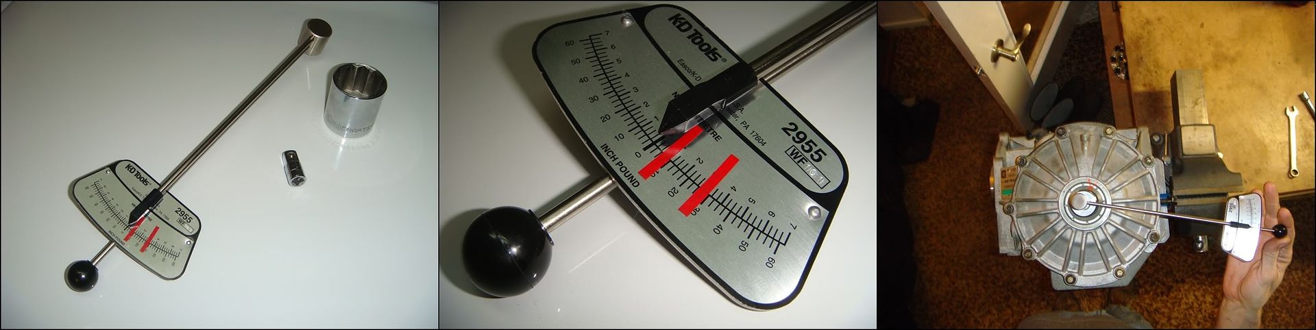
To take this measurement, you will need to remove the pinion assembly. If the pinion is in position, it will raise the torque required to turn the carrier and screw up the measurement completely. The rotating torque can be measured with a torque wrench; more specifically a �beam� torque wrench. The �clicker� type won�t work for this. I�ve found that a 30mm 12-point socket slips perfectly over the output shafts, and with a 1/4 - 3/8 adapter, we were in business. We assembled the carrier into the case with the LH shims that we calculated above. The RH shims were added to achieve zero pre-load, and an additional 0.1mm was added as a good starting point. The RH cover was torqued down and the case was mounted onto the holding fixture with the short RH shaft pointing up. Reading the torque wrench while its moving is a little tricky. I drew two lines on it indicating the allowable range, and just watched where the needle settled between the two...the closer to the middle, the better. One important point: the torque required to get the carrier moving is considerably greater that what's required to keep it turning at a constant speed. It's the second value that we are interested in here. You'll need to get it turning at a nice constant speed before you check the reading. As it turns out, our first reading fell between the lines, closer to the low end of 10-25, but good enough for me. Obviously, if it falls outside of the allowable range, add/remove shims from behind the RH race and re-test.
Backlash Measurement and Adjustment
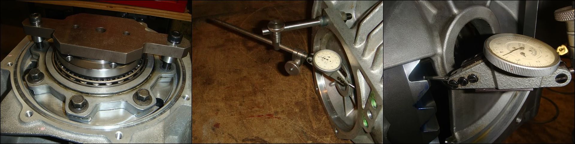
The final measurement to make is gear backlash. This is the space between the meshing teeth of the ring and pinion. Measuring this is easy. It simply involves locking the pinion from turning, jiggling the ring gear back and forth, and measuring how much it moves. At this stage, both LH and RH shims must be in position, and the carrier/ring gear must be installed with the RH cover torqued down. The pinion assembly with shims must also be torqued into position. I used my homemade version of J-42168-11 to lock the pinion, as shown in the first photo. The manual suggests using J-42164 for this purpose, though I�m not exactly sure how that works. The tool fits into the pinion splines from the back, but how the tool locks to the case is beyond me. The manual can be pretty vague at times. Regardless, just make sure the pinion is securely locked down so it can�t budge. The next step is to mount the dial indicator to the case. The little post bolted to the case in the second pic is the easiest way I can see to do this. I just welded a piece of 3/8� rod to a 3/8-16 screw, and held it in position with a nut from the back. You can also use a length of 3/8-16 threaded rod with two nuts. The adjustable bar will lock directly onto this threaded rod. The most important point here is that the indicator stylus be square with the gear tooth. You don�t need to lose your mind here, but the more angle there is, the more error the reading will have. With the style of indicator shown above, the angular error can be kept to virtually zero. Once the pinion is locked and the indicator set up, lift the ring gear up as high as it will go with your fingers and make a note of the indicator reading (zero it if you want). Then lower the gear as low as it will go and watch how much the reading changes. This is your backlash. Repeat this several times to make sure you get a consistent reading. The backlash should be between 0.0067� and 0.0082�. If it�s out of spec, don�t look to the manual for guidance, cuz it has none to offer. I adjusted backlash by changing the LH shim stack. Adding to it will increase backlash, and decreasing it will reduce backlash. Remember that as you add/subtract from the LH shims, you must make opposite changes to the RH shims in order to maintain proper preload. Just make sure that the two sides always add up to the same value. A good recommendation that the manual does make is to take several backlash measurements at different points around the ring gear, and average them. Due to run-out and other manufacturing errors, the readings are bound to vary a little.
Checking Gear Mesh
And now for the moment of truth. By painting the teeth with gear paint, or in this case, high spot blue, we can see exactly how the two gears mesh together. This is what all the measurements and calculations laid out above were all for. This is the �last word�... if the mesh pattern doesn�t look good here, something went wrong and further adjustments need to be made. Kind of exciting actually seeing it all come together like this. And this really is a pretty reliable indicator of good gear set-up. Nice to know when you�re still looking at many, many hours completing the reassembly and putting the car back together.
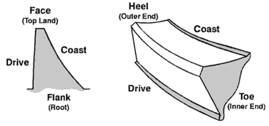
But first some gear lingo. The heel end of the tooth is at the OD of the gear, and the toe is the end of the tooth towards the centre of the gear. The drive side of the tooth is the side that contacts the pinion during acceleration( the convex surface of the tooth), and the coast side(concave surface) is the surface that makes contact with the pinion during deceleration.
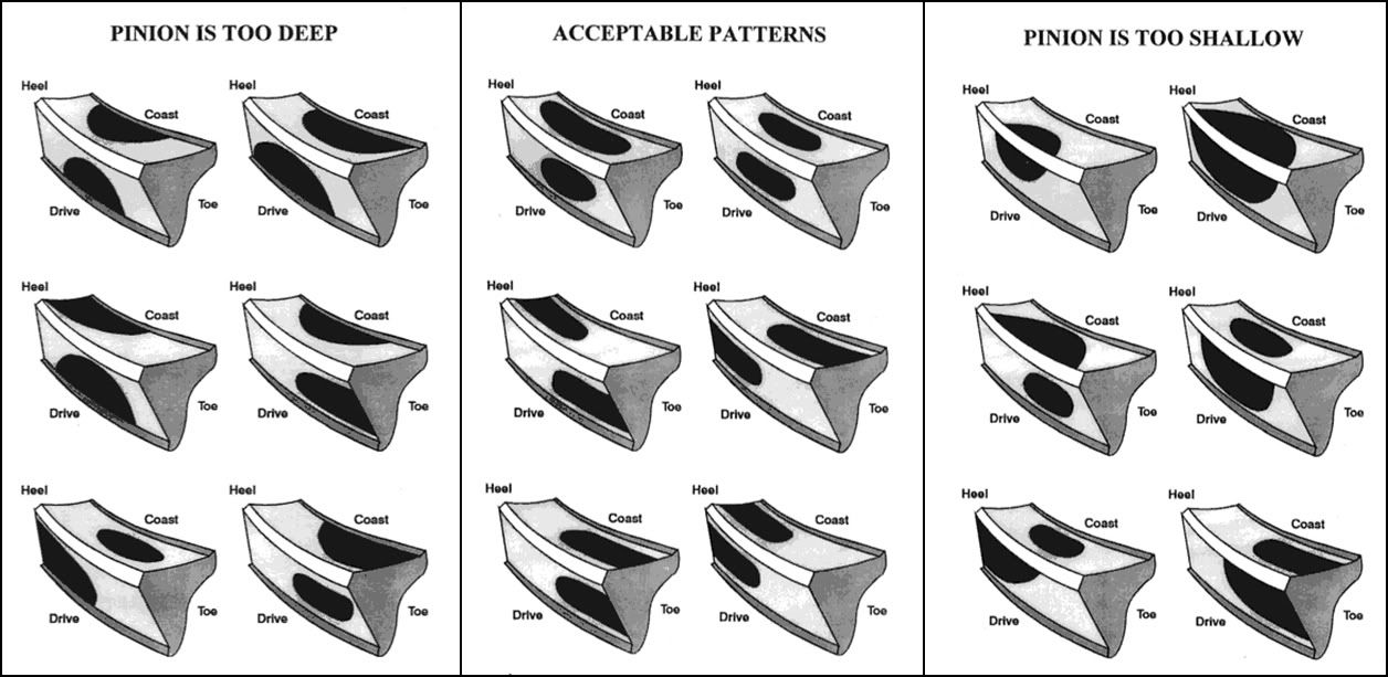
This shows various mesh patterns and the effect of pinion position. In a nutshell, the ideal pattern is centered on the tooth, both lengthwise as well as along the width. Try and avoid a pattern that runs off the top of the tooth or into the root. Getting it perfect is probably an exercise in frustration more than anything, so just shoot for decent centering between the root and top edge of the tooth.
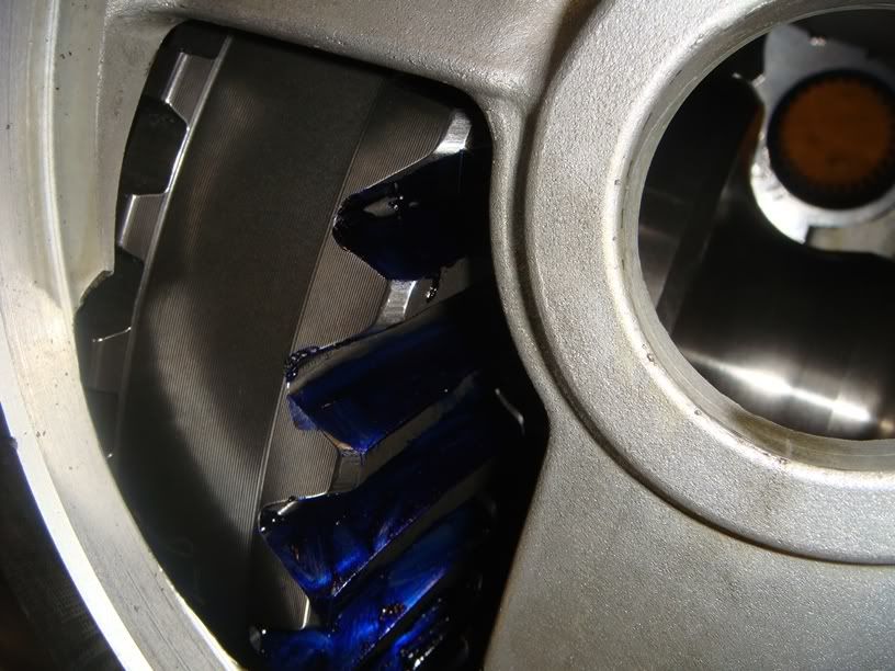
I painted the ring gear teeth with �high spot blue�. I applied it to both sides of about 6 teeth with a Q-tip. Pretty straight forward�just make sure you get the entire surface on both sides and don�t miss any spots. I then used the pinion nut tool in a �" impact gun to turn the pinion. I ran it thru about 20 revolutions, both forward and reverse until a nice pattern formed on the remaining un-painted teeth.
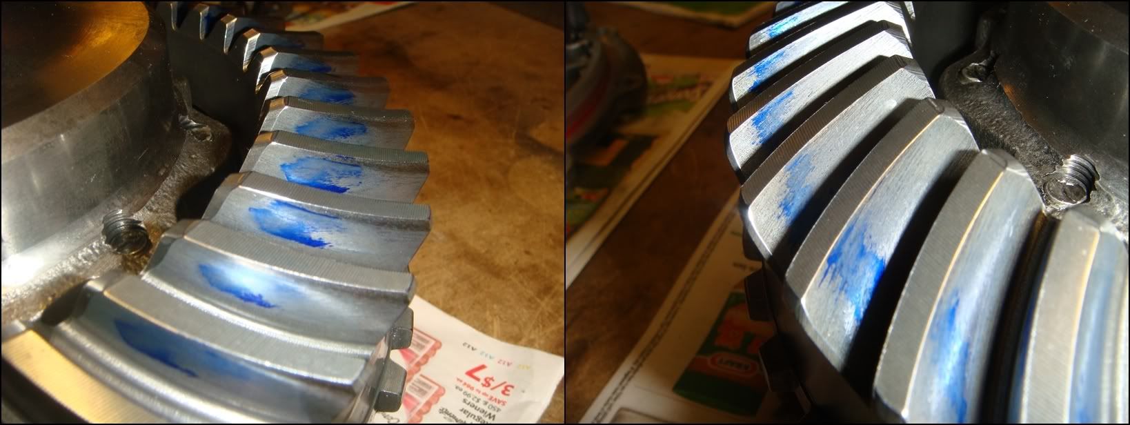
And here it is. Perhaps the pinion is a tad shallow, but I�m happy with it. This pattern proved to be very quiet with no issues whatsoever. Now let�s put this thing back together�
This part of the project can be broken down into four separate steps:
1) Select LH shim stack to position the ring gear properly within the case left-right. (Setting Dimension "A", below)
2) Select shims to position the pinion assembly within the case fwd/aft for proper mesh.
3) Select RH shim stack to provide proper preload for both side bearings. (Setting Dimension "B")
4) Check backlash, and adjust the LH shim stack if necessary.
The differential carrier is mounted onto two tapered roller bearings. The races in which these bearings ride are pressed into bores machined into the case. On the RH side, the race is bored into the side cover. On the LH side, it�s bored directly into the main case. The LH and RH shim stacks pictured above slip into these bores before the races are pressed in. The difference between dimension B above and dimension 1 below is the side bearing preload, set by the RH shims. Because the LH shims control ring gear location and the RH shims are then added until the proper preload is obtained, the two shim stacks will more than likely be of different thickness. Don�t assume that they are the same!
The first step is to position the ring gear L-R within the case (the only adjustment it has). The ring gear teeth are machined onto a blank which then bolts onto a machined surface on the differential carrier. The critical dimension here is where those teeth are cut with respect to the mounting surface. And, as always in manufacturing, there is a tolerance associated with it. The manual refers to it at a manufacturing variation, and it's the reason you can't just swap in new gears without adjusting (or at least checking) their position. There is also a tolerance associated with the location of the carrier mounting flange. The new gear will bolt-up in exactly the same place as the old, but the teeth will most certainly be in a slightly different location with respect to the mating pinion teeth. The A2 value marked on the ring gear by the manufacturer is the "magic number" which tells us exactly where those teeth are relative to the mounting flange.
LH Side Shim Selection
The selection of this shim stack involves measuring where the ring gear is located with respect to the pinion centerline. Manufacturing tolerances applied to the case, differential carrier, pinion, ring gear, and bearings all conspire to make this dimension an unknown unless it is actually measured. To make this measurement, you will need these special J tools: J-42168-2, J-42168-11, J-42168-7, and J-42168-13.
NOTE: Not all ring/pinions come with an A2 value engraved on them. The factory sets should all have both A1 and A2 values, but aftermarket gears may not. They should ALL have A1 though, which is needed to set pinion depth. If this applies to you, the following factory process for selecting the left hand side shims will not work. The alternate method will involve setting the pinion depth FIRST, then selecting LH shims that produce a backlash value between .0067� and .0082�. This will be a trial-and-error process. I recommend using the same LH shims that were used in your original set-up as a good random starting point. If the backlash is tight, add shim. If backlash is too loose, remove shim. Setting backlash properly is key to a quiet, happy rear end, so don�t get frustrated here and just say �good enough��a noisy rear after so much dicking around would really bite.
If, however, your gear-set has an A2 value, shim selection is a much more exact process�
This is the first of two measurements made using J-42168-2. This is probably the most critical measuring tool used to build this differential. Along with J-42168-1, they are solely responsible for how the ring and pinion mesh�at least until we check it with high spot blue. This tool measures the fore-aft distance between the pinion locating flange and the centerline of the carrier. It also measures the L-R distance between the pinion centerline and the LH carrier bearing bore. These two measurements will tell us how much to shim the ring gear to the right, and how much to shim the pinion back to get a good mesh pattern on the gears. To use this tool, it must be assembled with bearings and spacer into the pinion housing, basically replacing the pinion in the assembly. The bearings are a smooth slip-fit onto J-42168-2, so assembly is a breeze. Slide the front bearing on first, followed by the preload spacer, and then install this assembly into the pinion housing. The pinion housing must have both outer races installed.
Flip it up on the work bench and slip the rear bearing into place. Then the clamp that holds it all together can be fitted. Lightly snug the center bolt to hold the assembly together. Make sure it�s tight enough to remove any play from the bearings. A little tighter is better than a little looser here. The homemade clamp-bar shown here orients J-42168-2 properly in the case by using two of the eight pinion housing screws. The factory tool allows the assembly to still turn somewhat; it is positioned properly by turning it until the lower probe rests against the web cast into the case (see below).
Now lower the completed assembly into the main case and torque all 8 screws to 18 lb ft. If these screws are not tightened properly, the measurement taken may not be accurate. The second pic shows how it should look from inside the case. The small hole in the upper probe should point directly down towards the bearing bore below. Now that J-42168-2 is in position we can finally begin taking measurements. The first measures the sideways position of the ring gear relative to the pinion. For this, we need to use J-42168-7, what GM refers to as a �depth gauge�. It�s simply used to �transfer� the distance from the top of the upper probe to the bottom of the bearing bore to the next tool shown below, where the actual measurement will take place. Position J-42168-7 by inserting the long gauge pin into the small hole in the probe, and then slide the whole thing down until it rests level against the probe.
Loosen the thumb screw to allow the gauge pin to slide up/down. Press down lightly on the depth gauge to ensure it is sitting level with the probe. If it�s not level, the accuracy of your measurement will suffer. At the same time, press down lightly against the top of the pin so it contacts the bottom of the bearing bore. Once you�re satisfied that everything is level and touching properly, tighten the thumb screw to �lock in� the setting. Don�t tighten the crap out if it, or the end of the screw will sink right into the pin. The next time you use it, it will try to pick up the indentation and throw your measurement off. Gently slide the gauge straight up and out, obviously being careful not to disturb the setting.
To get J-42168-13 ready, first wipe down the area shown above. Make sure it�s completely clean, and then drop the LH bearing race into place. Lower the carrier assembly onto the bearing race as shown. Turn it back and forth a few times to ensure the bearing is seated properly. The carrier shown above has its output shafts removed, but this can also be done with the shafts in place. If the shafts are present, clamp the gauge plate in a vice to allow the long LH shaft to poke out the bottom. Also check that the ring gear bolts and housing bolts are all torqued properly.
These two pics show where the depth-gauge (J-42168-7) attaches to the ring gear. The first photo shows where the factory tool goes. The tool is simply pushed in until it jams tight. There are two slots like this, spaced 180 degrees apart. These slots are identical on both 2 and 3 series carriers. The second pic shows where my homemade tool attaches. It simply lays flat on this surface, with the embedded magnet holding it firmly in position. This is actually part of the cross-shaft pin bore. The carrier shown is a 2 series; the 3 series looks slightly different.
Set J-42168-7 into position and then rotate the carrier until the gauge pin is over the gauge block. The gauge block has two levels on it; use the upper level for 2 series carriers, and the lower for 3 (and 4) series. Feeler gauge the gap, and record this dimension as C1. Make absolutely sure that the depth-gauge remains flat and parallel with the ring gear while the gap is being measured. I recommend putting slight finger pressure on it to keep it flush with the gear. Try not to use more than two feeler gauges at once as the more gauges in the stack, the less accurate the measurement becomes. I usually free the blades from the holder so I can pick and choose the right sizes easier.
Now for the first round of calculations. The first step is to subtract C1 from a C nominal value of 5mm (.0197 in). Record this value as C2.
C2 = .197� � C1
In this particular case, C1 measured in at .040�, so C2 becomes .157�.
Locate the A2 value engraved on the side of the ring gear. From the manual: �The A2 value is a manufacturing variation between the ring gear and the pinion. The A2 value may be higher, lower, or equal to 65.5mm (2.58 in) for 3.15 and 3.42 ratio differentials, or 74.5mm (2.93 in) for 2.73 ratio differentials, nominal value. When subtracting the D nominal value from the A2 value, the C3 calculation may compute to a positive, negative, or zero total.� In other words:
C3 = A2 � 74.5mm for 2 series carriers,
Or
C3 = A2 � 65.5mm for 3 (and 4) series carriers.
In this case A2 is 74.49mm for a 2.73 carrier, so C3 calculates to -.01mm
Because C1 will most likely be measured with Imperial (inch) feeler gauges, C2 will also be in inches. C3 will be a value expressed in millimeters, because the ring gear A2 value is given in mm. A conversion needs to be made before the two can be added. Personally, I prefer to work in inches�so I simply convert C3 into inches by dividing it by 25.4.
C3 (inches) = C3 (mm) / 25.4
In this case, C3 becomes -.0004�.
And finally:
LH differential bearing Shim Thickness = C2 + C3
For this example, the final shim stack worked out to .1566�.
From the manual: �select shims equal to the calculated value. It may be necessary to round the shim or shims total to obtain the proper shim sizes. If the shim thickness calculation is past the midpoint value, round the value to the next decimal value.�
GM produces side shims in 12 different sizes:
1.00mm 0.0393 in
1.25mm 0.0492 in
1.30mm 0.0511 in
1.40mm 0.0551 in
1.50mm 0.0590 in
1.60mm 0.0629 in
1.70mm 0.0669 in
1.80mm 0.0708 in
1.90mm 0.0748 in
2.00mm 0.0787 in
2.10mm 0.0826 in
2.20mm 0.0866 in
From the table above,
0.0669 and 0.0866 forms a stack .1535
0.0708 and 0.0866 forms a stack .1574
with .1555 as the midpoint between the two.
Because our calculated thickness of 0.1566 is past the midpoint, I will use 0.0708 and 0.0866 as the final shims.
Note that the shims go up in increments of 0.1mm, except for the second one (1.25mm) which has a 0.05 increment. That makes this one useful for fine tuning the stack thickness. In the case above, if we used the THREE shims: 0.0039, 0.0492, and 0.0669, we would produce an overall thickness of 0.1554, which is right in the middle of the two stacks above. The midpoint between this stack and the next stack up (.1574) is 0.1564, which is pretty much the calculated thickness we need. This means that we could use either one. I would much rather use two shims than three, so I�ll go with the two shim stack of 0.1574.
Pinion Shim Selection
The next step is to measure where the pinion is fore/aft with respect to the ring gear centerline. As mentioned above, J-42168-2 is also used to accomplish this. However, this time it is used in conjunction with J-42168-1. J-42168-1 simply extends the centerline of the carrier bearings out under J-42168-2. The first step is to rotate J-42168-2 so that there is enough room to insert J-42168-1 into the bearing bore. In my case, I had to remove the two screws locating the tool to the case, allowing it to rotate on the pinion bearings. If using the factory tools, the tool can simply be spun out of the way. Once there is enough room, slide J-42168-1 into position in the LH bearing bore. Clamp it into position with holding strap J-42168-9 from the other side.
Once the centerline cylinder is in position, rotate J-42168-2 back down until the shorter probe lines up with it. With these homemade versions, I just bolted down the alignment strap to lock J-42168-2 down into this position. The factory tool simply bottoms out against a web cast into the case, which keeps it from rotating any more. Now, feeler gauge the gap between the two. As mentioned above, try and use no more than two feelers together at once for better accuracy. Write this value down, referred to as B1 in the manual.
Now come the second round of calculations, used to come up with the pinion housing shim thickness. The first is a simple modifier to B1, measured above. These tools are designed with a nominal gap of 5mm(.197�), which ensures that no matter how the manufacturing tolerances of the various elements(case machining, pinion bore machining, pinion housing machining, bearing thickness, pinion machining�etc) add up, there will ALWAYS be a gap between the two tools. If the feeler dimension measured here were .197�, it would indicate that the tolerances for all these various elements added to give the exact designed position of the pinion within the case. Any deviation will indicate how far the position of the pinion is out of tolerance. The value measured above is simply subtracted from this nominal value, giving us B2
B2 = .197� � B1
In this case, B1 measured in at 0.158 so B2 works out to 0.039
The next step is to read the A1 value engraved into the ring gear. In the example below, A1 = 103.00mm
From the manual: �The A1 value is a manufacturing variation between the ring gear and pinion. The A1 value may be higher, lower, or equal to 103.00mm (4.055�) nominal value. When subtracting the A nominal value from the A1 value, the B3 calculation may compute to a positive, zero, or negative total�. In other words, B3 = A1 � A, where A is a nominal value of 103.00mm. As above, any deviation from the nominal dimension (103.00mm) will indicate the machining error in the gear set. In this case, the pinion was machined **** on, with B3 (error) computing to 0.
B3 (mm) = A1 � 103.00
In this case, B3 works out to 0
Please note, because B1 will most likely be measured with Imperial (inch) feeler gauges, B2 will also be in inches. B3 will be a value expressed in millimeters, because the ring gear A1 value is given in mm. A conversion needs to be made before the two can be added. Personally, I prefer to work in inches�so I simply convert B3 into inches by dividing it by 25.4.
B3 (inches) = B3 (mm) / 25.4
0 inches equals 0mm�
So finally:
Pinion Shim Thickness = B2 + B3
Pinion shim thickness = 0 .039 + 0 = 0.039.
Again, from the manual: �Select shims equal to the calculated value. It may be necessary to round the shim or shims total to obtain the proper size shim pack. If the shim thickness calculation is past the midpoint value, round the number higher to the next decimal value.�
GM produces pinion shims in 5 different thicknesses:
0.20mm 0.0078�
0.25mm 0.0098�
0.30mm 0.0118�
0.50mm 0.0196�
1.0mm 0.0393�
The 1.0mm shim matches the calculated thickness almost perfectly, so that�s the one we will use. Otherwise, use the same process as with the side shims to select the best possible combination.
RH Side Shim Selection
This last shim sets the �axial preload� on the two carrier bearings. When the carrier is installed back into the case and the RH cover torqued down, the two bearings are pressed towards each other with a slight force called preload. Setting this properly will help ensure maximum bearing life and quiet operation. If preload is nonexistent and the bearings have slop in them, the mesh between the gears will be inconsistent and they will be noisy. If preload is too high, the bearings will overheat and fail prematurely. This measurement has to wait until the carrier has been fully reassembled, so it�s a little out of order here. Once you reach the point where the LH shims/race are pressed in and the carrier is back together with shafts, clutches, etc, skip back to this section to measure the preload and select the RH shims.
If you are using the factory tool for this, the procedure is very easy. Mount the case onto the holding fixture with the RH cover flange pointing up. Slide the carrier down into the case and make sure the bearing seats properly into the race by turning the carrier back and forth a few times. Now lay the RH bearing race down onto the bearing and seat it in the same way. Lay the "side bearing shim selector" tool, J-42168-15 onto the race, and lower the RH cover down over it so it pokes out the top. You'll notice that you won't be able to lower the cover on flush with the case...that's what the spacers are for. Using the three spacers and the longer bolts provided with them, bolt the cover to the case. All that's left to do is to feeler gauge the measuring gap in the tool. This dimension is the RH shim thickness. I found this picture on the forum some time ago, but I'm pretty sure credit for it goes to Rick@RKT56. Rick is a fantastic source of info regarding these differentials and is a great person to turn to for help.
In the absence of the factory tool, the bearings can still be set accurately. By measuring the distance inside the case between the two lands that support the bearing races, and measuring across the two races as they sit on the installed carrier bearings, the preload can be calculated. To measure the distance inside the case, I made these two gauges. One gauge fits into each bore, and is held in place with a strap from the other side. When the side cover is fitted back onto the main case, the gauges will come within .010-.030 of each other. Knowing the exact length of each gauge, plus the feeler dimension between them, the overall width can be calculated. The LH gauge was made to a finished length of 3.025, and the RH gauge to 5.406. In this particular case, a .020 feeler was the thickest that would slide between the two, giving an overall width of 8.451.
The second measurement across the bearings races on the carrier were made using an attachment to the gauge plate J-42168-13. It measures the overall width of the rotating assembly that fits into the case bearing bores. The differential carrier, with both bearings and outer races in place, is placed onto the gauge plate. The round puck is then placed on top and the hydraulic press adds a little preload (through a spring) to make sure the bearings are seated properly. The dial indicator then gives the overall width of the entire assembly. This dimension, plus the RH and LH shim stacks must be GREATER than the case width, measured above, to achieve preload on the bearings. This carrier measured in at 8.451, giving a total preload of exactly zero. This �line-to-line�, no pre-load/ no clearance fit generally gives the highest bearing life in most taper-roller bearing applications, but is often times no good in gear boxes�especially hypoid ring and pinions. By adding pre-load to the bearings, deflections of the gears can be greatly reduced, maintaining proper gear mesh, and quiet operation. As bearings wear-in, their pre-load drops�used bearings can sometimes be set up with as little as half the preload of new ones to take this into account. The case also slowly stress relieves itself as it continually heats/cools, resulting in an additional loss in pre-load. In this case, the result was a total loss of bearing pre-load. Interesting, but not the end of the world�the gears will just gradually get louder as the bearings loosen up, assuming they loosen up more than this. What surprises me is that the factory tool doesn�t take into account whether the bearings are new or used when setting their pre-load.
Once the zero pre-load dimension is determined, the actual amount of shim to add can be determined by measuring their �drag-torque�, exactly as you do with pinion bearings. Guys who build differentials all day long can just give the carriers a spin when they are installed and tell if the bearings are tight enough. If you�re like me and can�t, measure it carefully and set it to what the bearing manufacturer suggests. As preload is added to a set of bearings, the shaft supported by the bearings becomes increasingly harder to turn. There is a relationship between the preload applied and the torque needed to turn the shaft. Measuring the rotating torque (also called �drag torque�) of the carrier is a very accurate way of setting the preload on these bearings. GM doesn't supply a torque value for the side bearings, so I had to do some digging. Interestingly, the torque values are very similar between varying designs and manufacturers. Values ranged a little, but anything from 15 to 30lb in for brand new bearings and 10 to 25 for used bearings will do the trick. This is very similar to the required pinion torque of 22lb in.
To take this measurement, you will need to remove the pinion assembly. If the pinion is in position, it will raise the torque required to turn the carrier and screw up the measurement completely. The rotating torque can be measured with a torque wrench; more specifically a �beam� torque wrench. The �clicker� type won�t work for this. I�ve found that a 30mm 12-point socket slips perfectly over the output shafts, and with a 1/4 - 3/8 adapter, we were in business. We assembled the carrier into the case with the LH shims that we calculated above. The RH shims were added to achieve zero pre-load, and an additional 0.1mm was added as a good starting point. The RH cover was torqued down and the case was mounted onto the holding fixture with the short RH shaft pointing up. Reading the torque wrench while its moving is a little tricky. I drew two lines on it indicating the allowable range, and just watched where the needle settled between the two...the closer to the middle, the better. One important point: the torque required to get the carrier moving is considerably greater that what's required to keep it turning at a constant speed. It's the second value that we are interested in here. You'll need to get it turning at a nice constant speed before you check the reading. As it turns out, our first reading fell between the lines, closer to the low end of 10-25, but good enough for me. Obviously, if it falls outside of the allowable range, add/remove shims from behind the RH race and re-test.
Backlash Measurement and Adjustment
The final measurement to make is gear backlash. This is the space between the meshing teeth of the ring and pinion. Measuring this is easy. It simply involves locking the pinion from turning, jiggling the ring gear back and forth, and measuring how much it moves. At this stage, both LH and RH shims must be in position, and the carrier/ring gear must be installed with the RH cover torqued down. The pinion assembly with shims must also be torqued into position. I used my homemade version of J-42168-11 to lock the pinion, as shown in the first photo. The manual suggests using J-42164 for this purpose, though I�m not exactly sure how that works. The tool fits into the pinion splines from the back, but how the tool locks to the case is beyond me. The manual can be pretty vague at times. Regardless, just make sure the pinion is securely locked down so it can�t budge. The next step is to mount the dial indicator to the case. The little post bolted to the case in the second pic is the easiest way I can see to do this. I just welded a piece of 3/8� rod to a 3/8-16 screw, and held it in position with a nut from the back. You can also use a length of 3/8-16 threaded rod with two nuts. The adjustable bar will lock directly onto this threaded rod. The most important point here is that the indicator stylus be square with the gear tooth. You don�t need to lose your mind here, but the more angle there is, the more error the reading will have. With the style of indicator shown above, the angular error can be kept to virtually zero. Once the pinion is locked and the indicator set up, lift the ring gear up as high as it will go with your fingers and make a note of the indicator reading (zero it if you want). Then lower the gear as low as it will go and watch how much the reading changes. This is your backlash. Repeat this several times to make sure you get a consistent reading. The backlash should be between 0.0067� and 0.0082�. If it�s out of spec, don�t look to the manual for guidance, cuz it has none to offer. I adjusted backlash by changing the LH shim stack. Adding to it will increase backlash, and decreasing it will reduce backlash. Remember that as you add/subtract from the LH shims, you must make opposite changes to the RH shims in order to maintain proper preload. Just make sure that the two sides always add up to the same value. A good recommendation that the manual does make is to take several backlash measurements at different points around the ring gear, and average them. Due to run-out and other manufacturing errors, the readings are bound to vary a little.
Checking Gear Mesh
And now for the moment of truth. By painting the teeth with gear paint, or in this case, high spot blue, we can see exactly how the two gears mesh together. This is what all the measurements and calculations laid out above were all for. This is the �last word�... if the mesh pattern doesn�t look good here, something went wrong and further adjustments need to be made. Kind of exciting actually seeing it all come together like this. And this really is a pretty reliable indicator of good gear set-up. Nice to know when you�re still looking at many, many hours completing the reassembly and putting the car back together.
But first some gear lingo. The heel end of the tooth is at the OD of the gear, and the toe is the end of the tooth towards the centre of the gear. The drive side of the tooth is the side that contacts the pinion during acceleration( the convex surface of the tooth), and the coast side(concave surface) is the surface that makes contact with the pinion during deceleration.
This shows various mesh patterns and the effect of pinion position. In a nutshell, the ideal pattern is centered on the tooth, both lengthwise as well as along the width. Try and avoid a pattern that runs off the top of the tooth or into the root. Getting it perfect is probably an exercise in frustration more than anything, so just shoot for decent centering between the root and top edge of the tooth.
I painted the ring gear teeth with �high spot blue�. I applied it to both sides of about 6 teeth with a Q-tip. Pretty straight forward�just make sure you get the entire surface on both sides and don�t miss any spots. I then used the pinion nut tool in a �" impact gun to turn the pinion. I ran it thru about 20 revolutions, both forward and reverse until a nice pattern formed on the remaining un-painted teeth.
And here it is. Perhaps the pinion is a tad shallow, but I�m happy with it. This pattern proved to be very quiet with no issues whatsoever. Now let�s put this thing back together�
The following 4 users liked this post by Its_Go_Time:
11-20-2011, 02:19 PM
#5
Burning Brakes
Thread Starter
Putting it back together, once the proper shims have been prepared, is pretty much the reverse order of disassembly. Some of these procedures need to be completed before the shim measurements can be made, specifically reinstalling the bearings if any are being replaced. Let�s start the reassembly with the carrier:
CARRIER REASSEMBLY
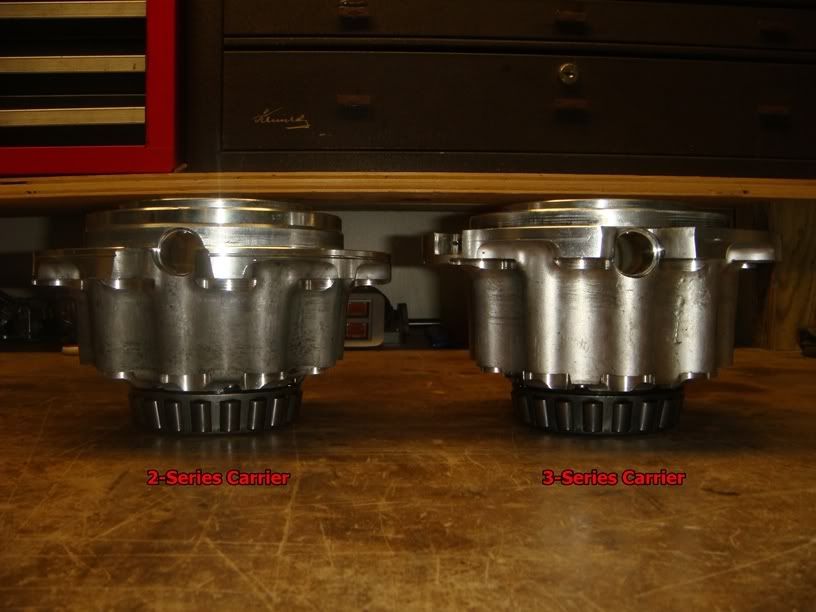
This picture clearly shows the difference between 2 and 3 series carriers. The 2-series has the ring gear mounted .354� further to the right (passenger side) than the 3-series. A 2-series carrier can still be used with 3.15, 3.42, 3.73, 3.90, or 4.10 ring gears by either using a spacer or a special �thick� ring gear.
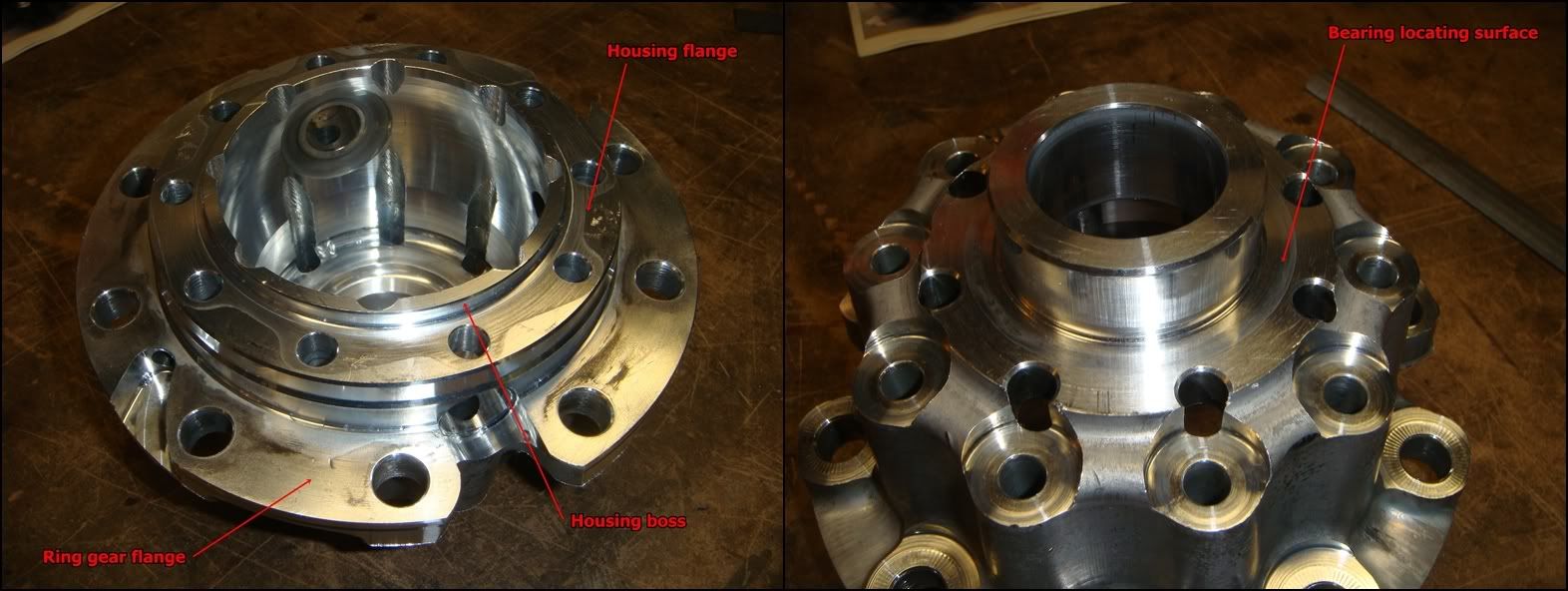
Before putting the carrier back together, take some time and inspect the housing for damage. Pay special attention to the areas noted above. Draw a fine file across the ring gear flange to remove any high spots or nicks. If the gear doesn�t pull perfectly flush with the flange, run-out will be excessive and it will be really hard to get a consistent mesh pattern between the ring and pinion. Draw your file across the housing flange where the two housing halves mate, and make sure the housing boss that aligns the halves together is free of nicks and burrs. Don�t go mental with the file�remember you�re working with aluminum here� Draw it flush across these surfaces, and let it tell you how flat they are. If there are no imperfections, the file will slide smoothly across without cutting very much. If any high spots appear, carefully file them flush. Remember that files only cut in one direction; draw it forward across the surface, then lift it up before pulling back. If you are replacing the bearings, pay special attention to the surface in the right-hand photo. If the bearing doesn�t press flush against this surface, the shims selected won�t be correct. They will be correct until the bearing eventually seats itself properly during operation, at which point the perfect gear mesh and bearing preload you set will fly out the window.
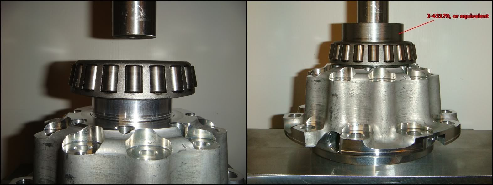
If ever there was a good time to slow down and take a deep breath, this is it. The object here is not so much to press the bearing on, but to press it on straight. If you take the time to set the bearing into position level and square before applying pressure from the press, you�re guaranteed to be golden. As you begin pushing the bearing down, watch to see that it �picks up� the boss and goes down straight. Otherwise, you risk �shearing� the aluminum as the bearing goes on crooked. If you damage the housing enough, it won�t hold the bearing tightly enough and might be junk. Honestly, all it takes is a little attention to all but eliminate this outcome. I�m always tempted to put oil on surfaces like this, but with the kind of press fit we�re talking about here, it just squeegees away as the bearing slides down. There�s just no room for it between the shaft and bearing. Maybe it helps, but somehow I doubt it. But if it makes you feel better, go for it.
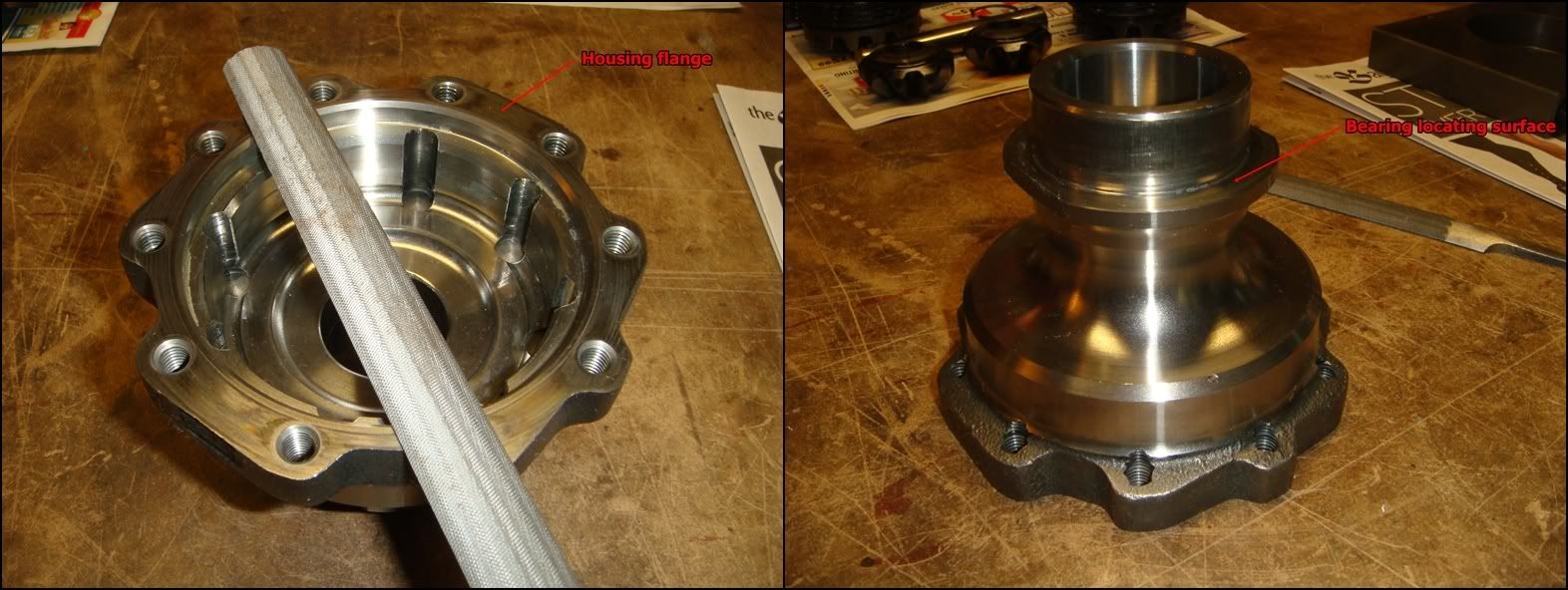
The cast iron half is next. As above, draw your file across the mating flange and carefully remove any high spots or dings. If the bearing was removed, also dress the flange it seats against.
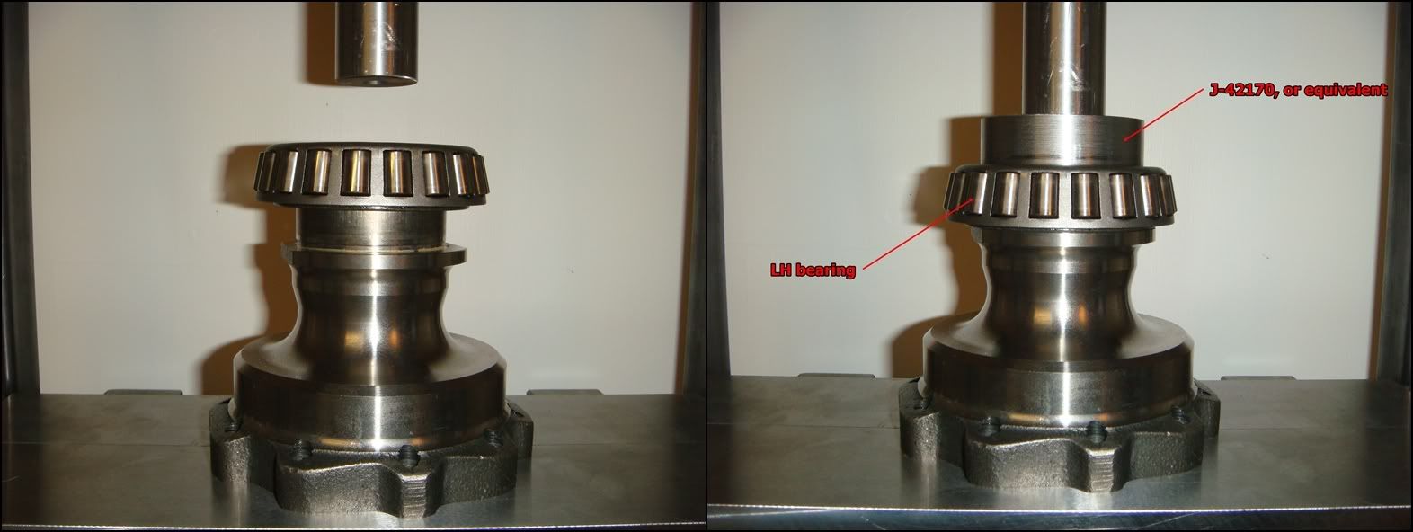
Like before, take the time and ensure that the bearing is sitting on the end of the shaft properly before hitting it with everything your press has. If you do, the bearing will go on like it had eyes of its own. Otherwise, if it starts going on wonky, you may have to press it off and try again. If this happens, make sure you didn�t leave any burrs or shear marks on the shaft. Make absolutely sure that the bearing has completely bottomed out on the housing�s shoulder
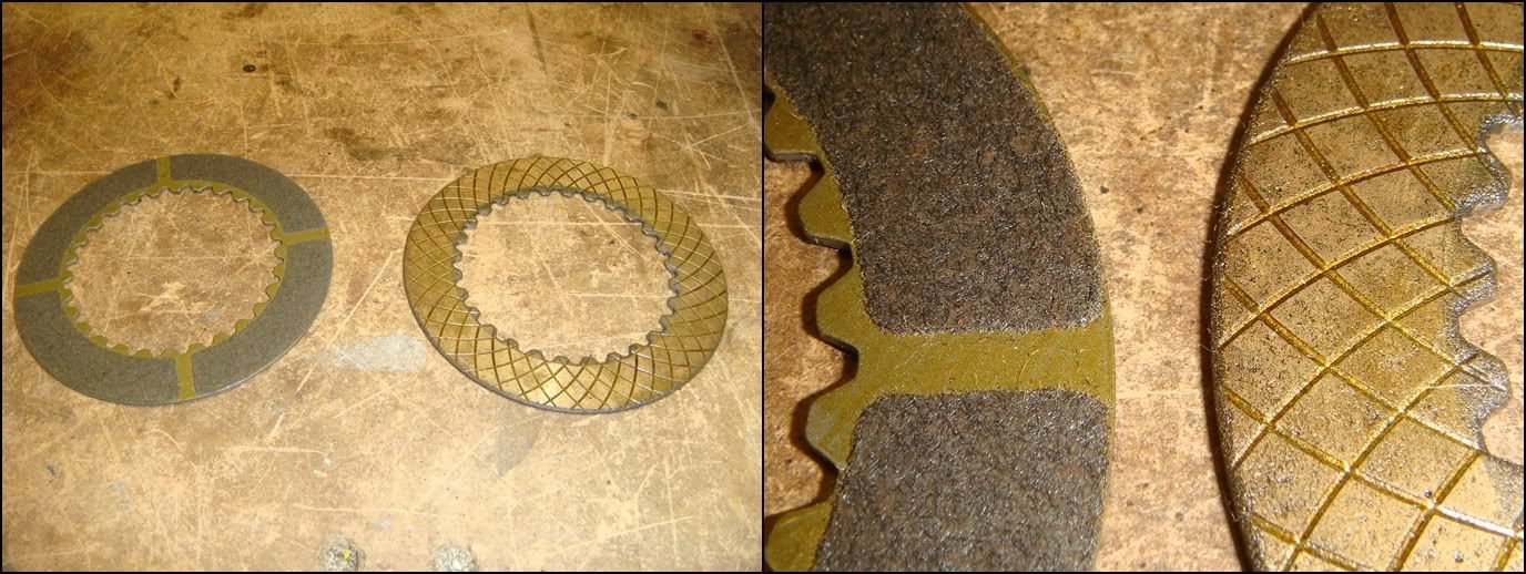
Once the bearings are in place, we can start to load the RH clutch assembly back into the aluminum half of the case. You must decide whether to replace the whole mess, or re-use the original components. Take a close look at every plate and look for signs of overheating or scoring. If the steels (disks without friction material) look discolored or warped, the clutch was probably slipping a lot and should be replaced. If the steels have deep scoring, they should also be replaced. If you decide to replace, you have a few options open to you: you can go with OEM C5 clutches, retro-fit OEM C6 ZO6 clutches which are a direct fit, or go with an aftermarket carbon clutch. Depends entirely on what you�re doing with the car. Remember that some slip is good, necessary actually, if you plan on doing any turning. Two things come together to create slip in these clutches: a grip imbalance between the left and right tires (which is always present), and torque input into the differential. For a given traction imbalance between the two sides, the more torque you try and put down, the more the clutches will slip. For the street, I personally wouldn�t hesitate to use the OEM stuff. If you do a lot of drag racing and don�t want to develop a peg-leg, the aftermarket clutches with stiffer springs might be a better choice�the trade-off will be more shudder during turning as the tires slip before the clutches. The best plan is probably to talk to the people who make this stuff, and don�t spend your money unless you really need it!
Above is a side by side comparison between a factory sintered clutch plate on the right, and an aftermarket carbon clutch plate. The carbon plates have much more grip than the factory piece, and therefore slip less. Here�s what one manufacturer has to say about their product:
CARBONETIC Carbon LSD Features:
� More than twice the differential lock strength of metal LSDs
� High carbon friction material increases the coefficient of friction
� Friction coefficient of metal plate in oil: 0.05 ~ 0.15 vs. carbon plate in oil: 0.25 ~ 0.35
� Low initial drag resistance with reliable performance - surpasses more than 5 times that of metal LSDs
� Acceleration control range in excess of 10 times that of metal LSDs
� Vehicle will remain on track in and out of turns for exacting driving control
� More than 30 times the thermal decomposition resistance of metal LSDs
� Promotes increased driving skill - repeated time attacks or under loads of performance cars
� More than 70 times the service life of metal LSDs
� Virtually noiseless performance
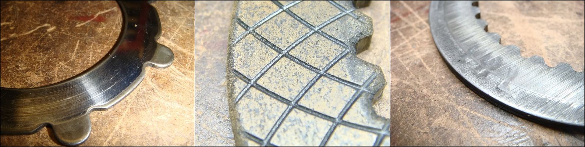
The used factory steel in the first photo above shows minimal scoring, and can be reused without problem. The frictions should be covered with friction material, with no peeling or separation. If the oil grooves are still present, as in the second photo, the disks still have sufficient lining to reuse. The last photo shows the back side of the thick friction plate, where the preload spring bears against it. Because the springs were both broken, the ends started to gouge into the disk surface. No problem�
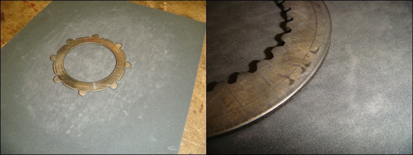
Any minor glazing or gouging can be removed by drawing the disk over a piece of 400 grit paper laying on a smooth, flat surface. Push down lightly with your fingers, and slide the disk around in a circle until the high spots or glaze go away. Of course, this is only for the steels�don�t start sanding your friction plates like this. The low spots left in the plate above are no problem because there is no sliding taking place on this surface. This plate is splined to the gear, so they always turn together, along with the preload spring in between.
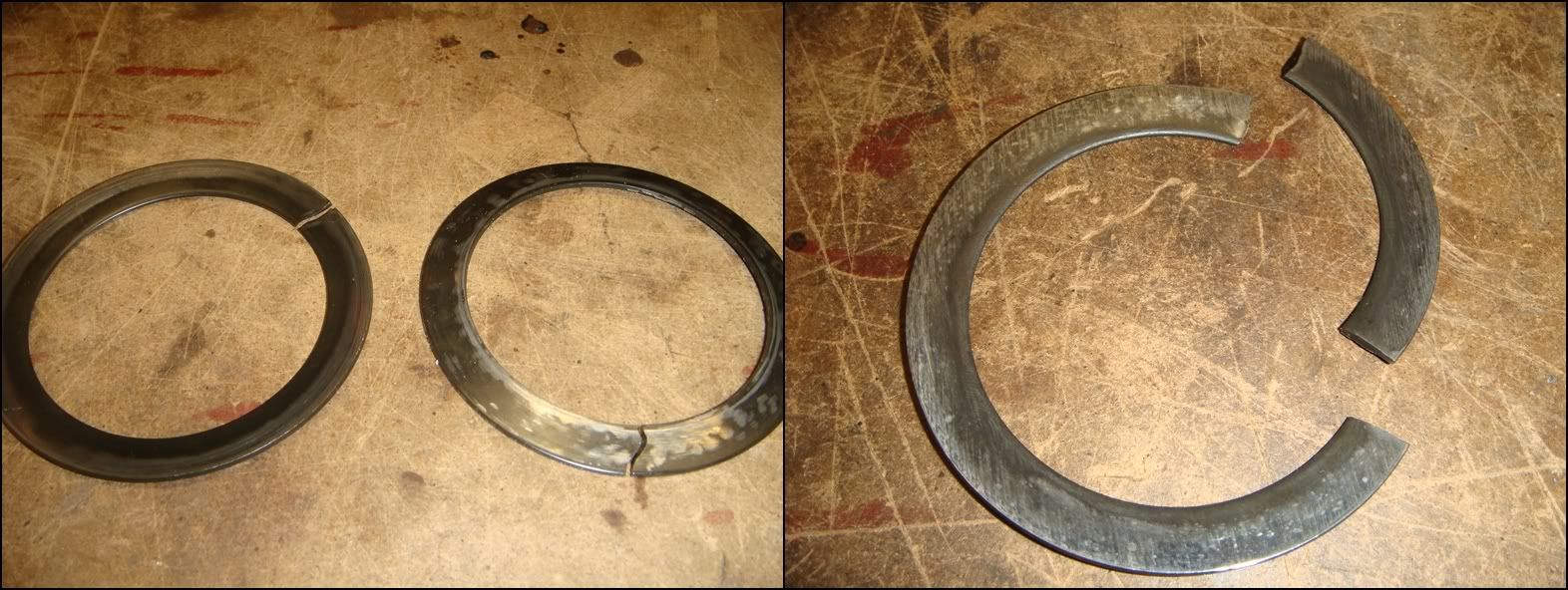
Speaking of pre-load springs, throw them out and get new ones. The factory pieces break all the time. Several aftermarket sources make much better replacements. Don�t even dream of reusing these, even if yours are somehow magically not broken! You�re probably looking at $15 each. The aftermarket pieces generally generate more clamping pressure, which isn�t a bad thing at all if it�s not over done. As mentioned above, some slippage is needed to ensure smooth cornering. From my personal experience, the 35% increase in clamping force generated by the springs sold by DTE had no detrimental effect on my car during turning. That was with the factory clutches. Using them with grippier aftermarket clutches might be a different story, though.
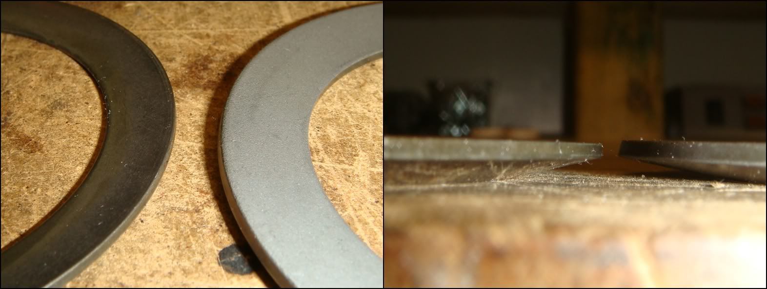
To the best of my knowledge, GM doesn't service the C5 springs separately, so you have to look elsewhere. I went with the springs supplied by DTE. They're pretty expensive, but worth it if they eliminate unnecessary clutch slippage. These pics show a comparison between the factory C5 preload spring on the left, and the DTE piece on the right. Here's what DTE has to say about their product:
Engineered Features of This Product:
-Manufactured of high strength tool steel w/ high carbon-high chromium content
-Forged to increase hardness and material density
-Extremely wear resistant (approx. double that of O.E.)
-Maintains its clamping load force over a greater installed height spread
-No distortion w/ high heat applications
-Temperature resistance of up to 1875* F
-Provides 34% more clutch pack clamping load over O.E. application
-Quiet operation on turns
-Provides increased posi traction operation and clutch pack life
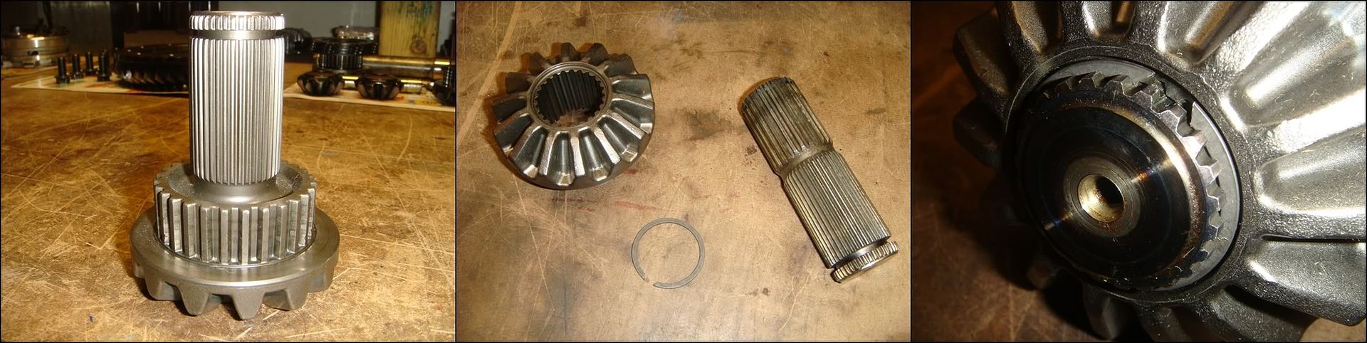
The next component to address is the RH output shaft/side gear. The factory C5 piece is shown in the first photo. As can be seen, it is of one-piece construction. Compare this to the two-piece construction of the C6 ZO6 piece in the second photo. The two designs are directly interchangeable with each other. I have heard that GM used better steel for their C6 output shafts, perhaps due to the chronic breakage problems of the LH C5 shafts. Whether this is actually true or not is unknown. But if you don�t want to take any risks, this is one option. The aftermarket also produces hardened 100M shafts of the two-piece variety for those who have lots of power and money to spare. If going with the two-piece style, ensure that the retaining ring has properly engaged into the shaft and gear, as shown in the third photo.
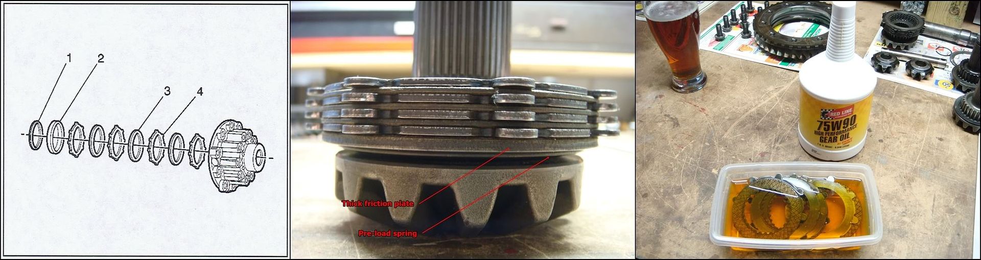
Now that all the parts decisions have been sorted out, we can reassemble the RH housing. Here, I am reassembling a factory C5 shaft with a factory clutch assembly. Before doing anything, soak the clutch assembly in gear oil. I stole some Tupperware from the wife, which is handy because I can seal it up when I�m done. I�ll pour this oil into the completed diff when I�m done. I�ve used Redline oil in my diff since day one with complete satisfaction. The friction modifiers used always made for happy, quiet clutches. The first drawing shows the order in which the plates must be installed. 1 is the pre-load spring, 2 is the extra thick friction plate, 3 are the friction plates which are splined to the gear, and 4 are the steels, which are driven by the case. I prefer to stack the clutch plates onto the gear assembly first, and then slide the whole thing into the housing. The second photo shows the clutch assembly installed onto the gear, along with the spring. Note the orientation of the spring: �Coning out� towards the clutch.
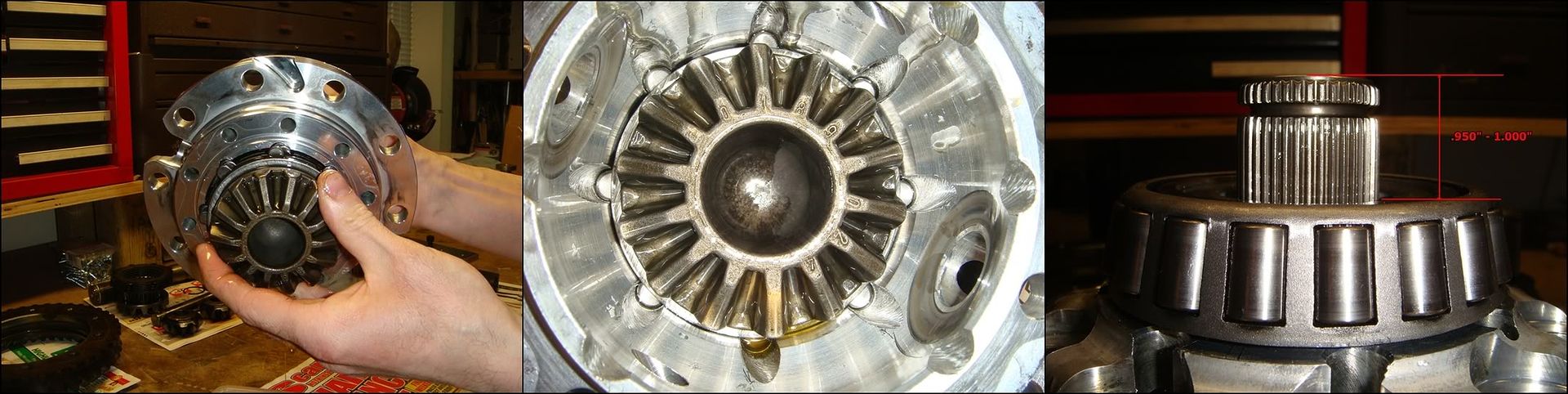
Now slide the gear/clutch assembly into the housing, jiggling and twisting until the tabs on the steels engage the grooves machined into the inside of the housing. Try not to pull the gear out as you do this or the plates might slide off of it. If this happens, the simplest thing is to just start over again. Trying to line up the splines to the gear and the tabs to the housing at the same time can be pretty frustrating. If everything made it into position properly, there should be just shy of an inch of shaft sticking out the other end. You�ll know for sure when you try and install the two spider gears and cross-shaft�if the shaft won�t go in, something�s wrong. The most likely culprit will be the first friction plate�if it slid off the end of the gear, it probably won�t be lined up on its splines, keeping the rest of the assembly from falling into position.
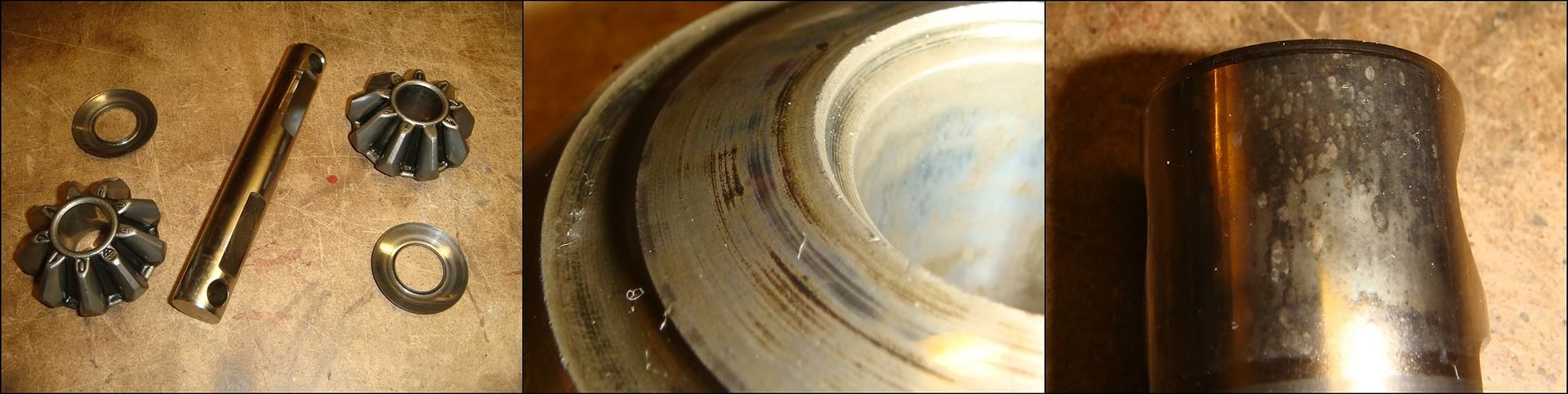
At this point, the spider gears can be put back in. Check the backsides of the gears and the concave washers for undue wear. Undue wear is a judgment call I guess. Mild scoring like in the second pic is ok, but if it�s munched, replace it. Check all the teeth for problems as well. I guess what I�m saying is actually look at everything closely� don�t just slap it all back together. It�s easy and cheap to fix problems now. Examine the cross pin for any unusual wear. It�s interesting to note that every single lb/ft of torque that you pump into the differential has to pass through this pin before reaching the wheels. If it breaks, you�re screwed. The aftermarket has it covered with high-strength, heat treated alloy pins. I think that they�re about a hundred bucks, which might definitely be worth thinking about if you�re pushing serious power. The stippling on the end of the pin in the third pic is no big deal.
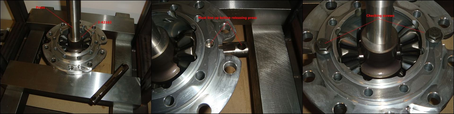
Once you�re happy with the condition of all the parts, begin by inserting the two gears with their respective washers roughly into position. Lube everything with gear oil. Insert J-42162 in between the gears, and place the whole set-up into the press. Start the pin into its bore and slide it in until it stops against the first gear. Using the press, press down on J-42162 enough to allow the pin to pass through the gear. You�ll probably have to wiggle the gear around a little before it lines up with the pin. If you oiled the gears and washers thoroughly, they will stick together as one and you won�t have to worry about the washer going AWOL inside the case. Keep pushing the pin until it passes through the second gear and into the case bore on the other side. The hole on either end of the pin must line up with the corresponding holes in the case. Two of the bolts that hold the two halves of the case together have to pass through the pin before they can thread into position. If you don�t line them up before you release the press, you�ll have to set it all back up in the press again to fix it. A simple way to check that everything is lined up properly is to simply slide a couple of the bolts into position�if they go in, you�re good to go. With that done, the aluminum side of the carrier is done.
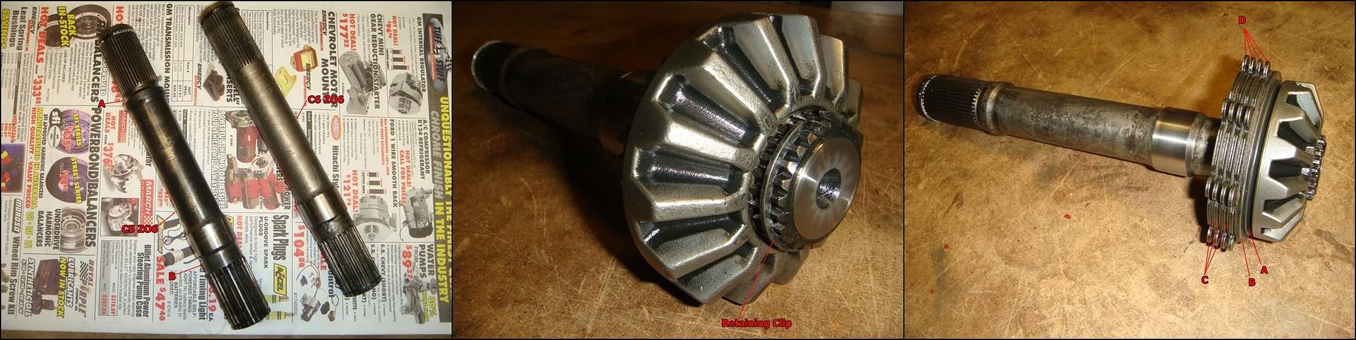
Now comes the cast iron half of the carrier. This is the side which contains the troublesome LH output shaft. These shafts have emerged as the definite weak link in these differentials, sometimes breaking with the least provocation. If you have some extra cash layin around, the aftermarket has you covered. Their shafts are made using a super strong alloy known as 300M, and even stronger materials are now available. But of course quality like this costs�expect to pay close to $300 for a 300M long shaft. Another option is an OEM C6 ZO6 shaft, which is considerably stronger than the C5 version. For $60-$70, it won�t break the bank, and will give you some extra peace of mind. The first pic is a quick comparison between the original C5 shaft on the left and the new C6 Z06 shaft on the right. Arrow A points to the strange undercut which leads to most of the failures of this shaft. This was eliminated on the new shaft...as well, the diameter at B was beefed up by about 10%. All other dimensions are the same. If you are changing the shaft, you must swap on the side gear from the old shaft. Simply remove the retaining clip and slide the gear off the old shaft and onto the new. If you were gentle with the clip and didn�t bend the crap out of it, you can reuse it no problem. The CV joint retaining clip on the other end of the shaft needs to be transferred as well. Once the gear is on, the clutch pack can be reassembled. The LH pack goes together in the same fashion as the RH pack. The preload spring, A, goes on first. Orient it so it �cones out� towards the clutch. Next to go on is the extra thick friction plate, B. Position it with the friction material facing away from the gear. The preload spring bears against the steel side of the plate. Now install a steel, D, and then a friction, C. Keep alternating between the two until you end up with something that resembles what�s shown in the third pic. The clutch should end with a steel, which will eventually bear against the cast iron housing.
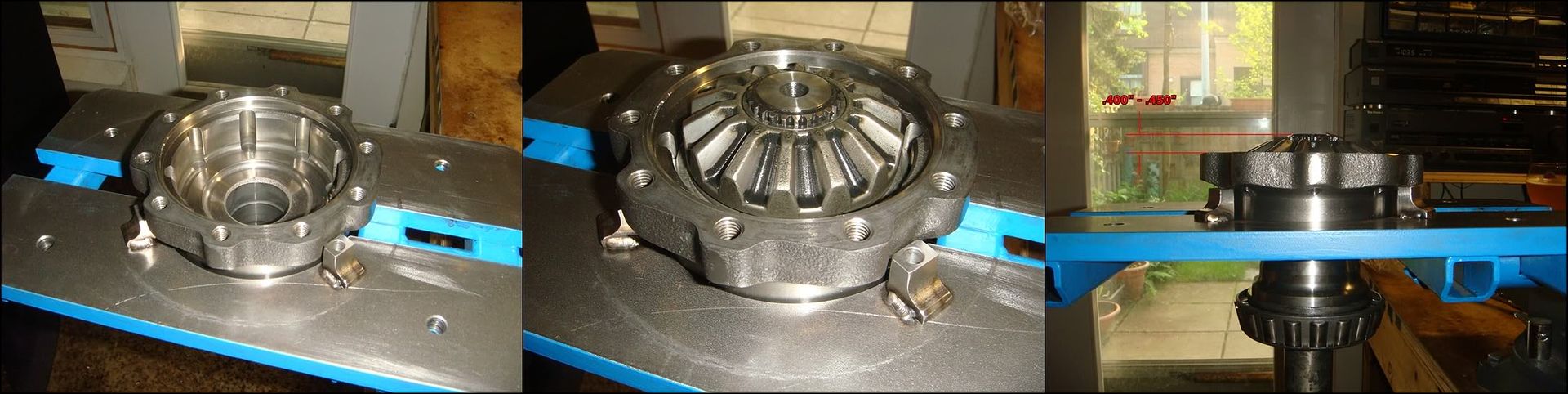
Now it�s just a matter of jabbing the shaft/clutch back into the housing. Using the holding fixture J-42173 to support the housing makes this a little easier to do. What I did is slide the shaft down into the housing while holding the clutch assembly with my hand. I held onto the clutch until the last moment, and then let it plop down against the housing, making sure the first steel didn�t line up with the grooves in the housing. I then used a scriber to turn the steels until they popped into position, gradually lowering the entire assembly into the housing. Once everything is in place and as far down as it will go, you should see about .4�-.45� between the top of the shaft and the housing mounting flange.
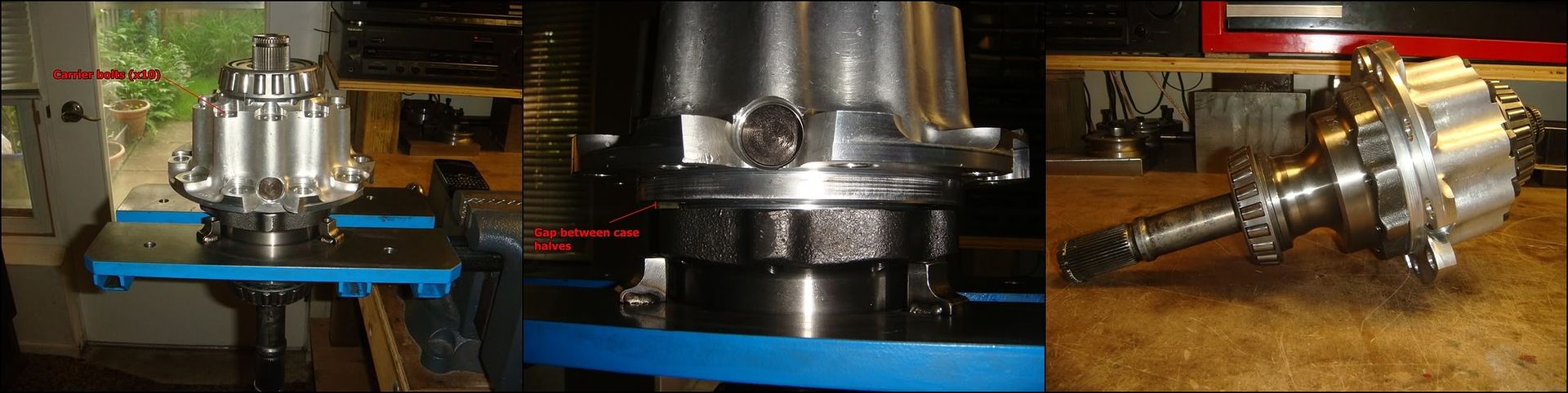
All that�s left to do is join the two halves back together. Just lower the aluminum half down onto the cast iron side, and line them up on locating boss, making sure the screw holes line up. Slide the ten carrier screws in and tighten them down until the heads just start to touch the aluminum. Now, tighten the bolts in small increments, using a criss-cross pattern to ensure the two halves don�t get cocked. The gap between them should stay even all the way around as the two halves come together. Once they bottom out against each other, torque the bolts to 41 lb ft.
Pinion reassembly
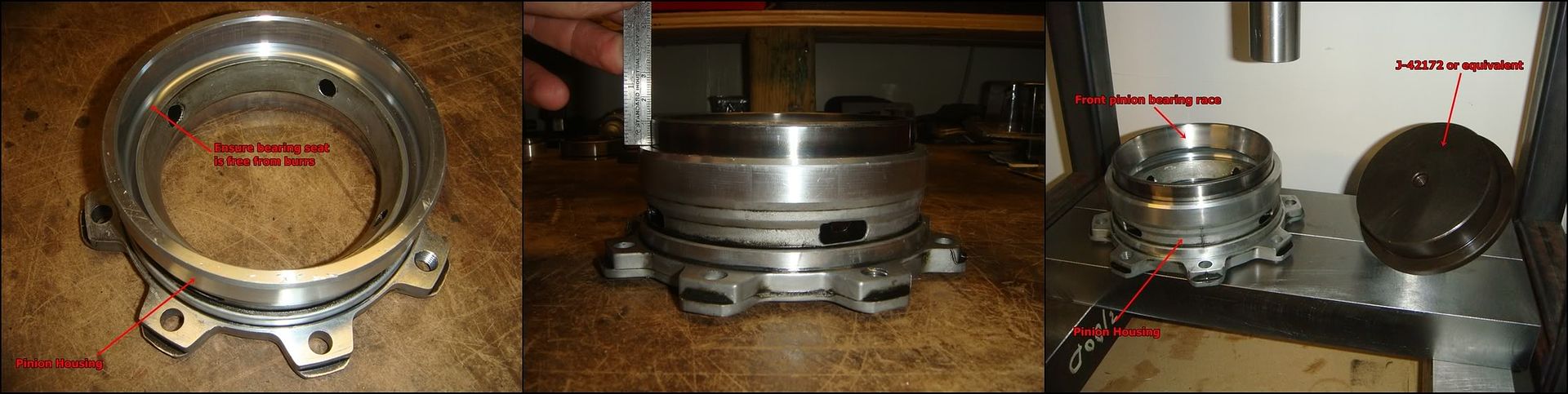
If the pinion bearings are being replaced, reassembling the pinion housing with the new races should be the first order of business. This will have to be done before the shim measurements described above can be made. This is because one of the measurement tools (J-42168-2) is positioned within the case by these bearings. As with the carrier bearings, make very certain the land that the race bottoms out on is free from any dings or burrs. If any exist, they will prevent the race from seating properly and result in improper pinion positioning and bearing preload. Smoothing away any high spots can be tricky because it�s so hard to get in there. Go and see what the wife sands her nails with. Mine uses these sandpaper popsicle-stick type things which are absolutely perfect�they can be broken into small pieces and remain flat, unlike sandpaper. Remember that you are working with aluminum here, so take it easy when you remove material�only small amounts of pressure are needed.
Once the housing is ready, lay the race(in this case, the front race) into position. Important: the bearing must be started in the bore square. If it isn�t square, you will almost certainly shear the soft aluminum housing when you try to press it in. If you take your time here and pay attention, I can almost guarantee you won�t have any problems. Tap the race slightly into its bore until it gets tight. It won�t go in very far�just make sure its snug. Use something soft like aluminum or bronze to avoid damaging the race. Take measurements all around as you tap and set the bearing as level as you can. In the second photo, I�ve tapped the bearing snug into its bore with about 12mm poking out, measured all around at 90 degree intervals. The race is now ready to be pressed in. For the front race, the service manual calls for J-42172 as the tool to use here, but you don�t really need anything fancy. I�m using a simple bushing installer, but a flat plate of steel big enough to cover the race would do equally well. When the race is fully installed, it still sticks out of the housing by about .020�, so the tool will never bottom out before the bearing.
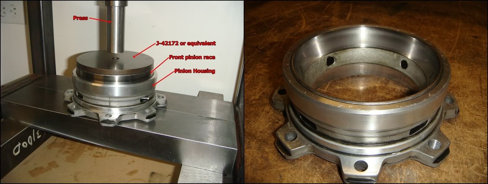
Now just set the housing into your press, place J-42172 into position, and push the race down until it positively bottoms out in its bore. If you lined it up nicely, it will slide in smoothly like it had eyes of its own. If it does start going in cockeyed, stop!!! Once it begins to go in wonky, it won�t straighten out on its own, and you might very well wreck the housing if you keep pressing. Press is out, and start again. Check the bore for any damage and carefully smooth it away with some fine (300-400) emery paper.
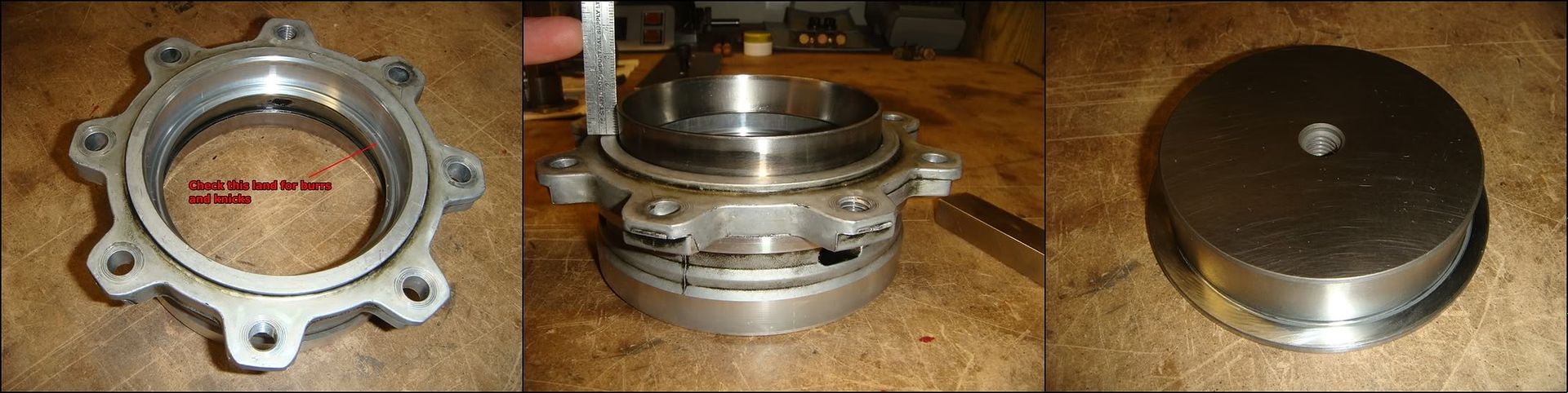
The rear race is done in exactly the same way. Again, the most important thing to do here is ensure the race is set up level in its bore before pressing it home. Due to the different diameter of this bearing, a different tool is required to press it in. The manual suggests J-42170, but a simple bushing driver, shown in the third pic, will also work.
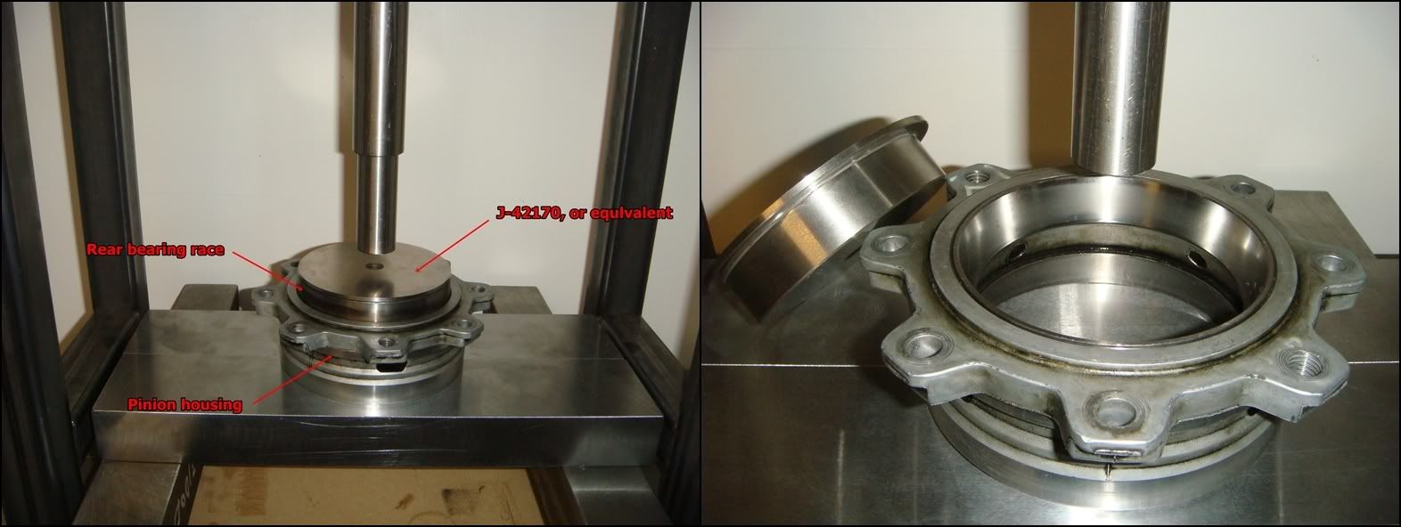
Once the race is pressed in square and to the bottom of the bore, give it a little extra shove with the press to absolutely ensure its bottomed out. Fully seated, the race will still stick up slightly (maybe 0.020�).
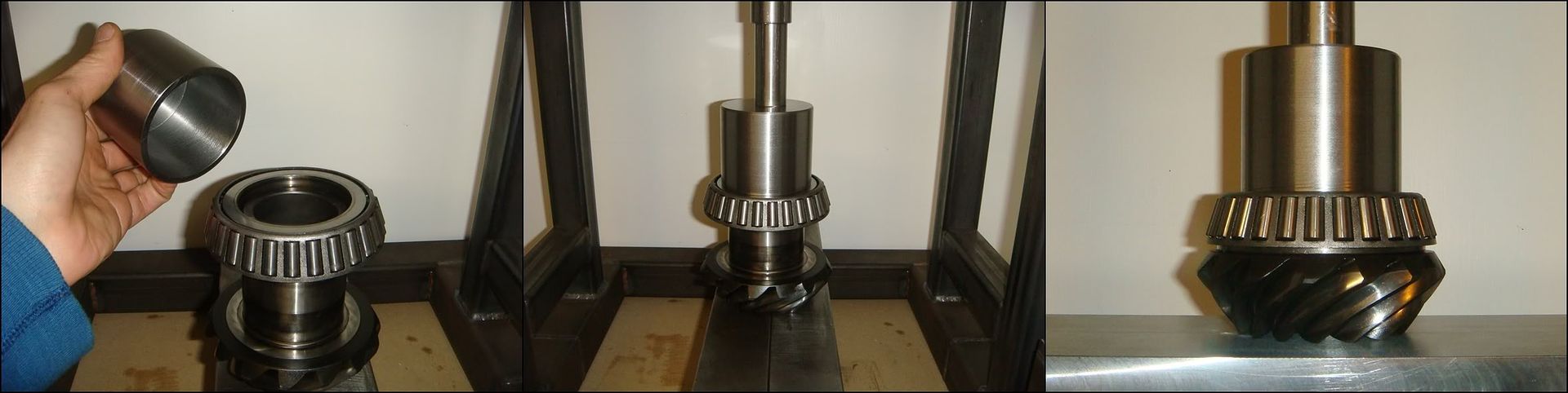
Now we can install the bearing cones back onto the pinion. The larger of the two (the front bearing) goes on first. Everything already written above regarding pressing on bearings applies equally here. Make sure everything is clean and free of burrs and high spots, especially the flat shoulder on the pinion, and the corresponding area on the bearing. The bearing must seat flush here. Set the bearing into position and tap it around until it is sitting level on the pinion. Lay J-42170 or something similar on top of the bearing, making sure that the pinion lines up with the hole in the tool. Press the bearing down until it seats against the pinion�s shoulder. Once it�s down, give it a little extra squeeze to ensure it�s seated. The manual suggests using J-42164 to support the pinion, instead of laying it down directly in the press as shown. That�s up to you�in my humble experience, the press fit on these bearings isn�t too bad�laying the pinion down directly into the press like this probably won�t screw it up too much.
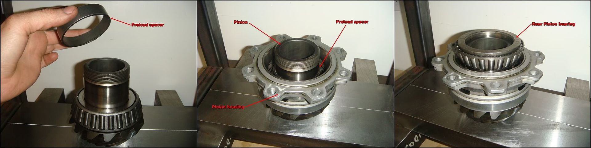
Once the front bearing is in place, slide the preload spacer back on. Make sure it�s the one that belongs with these particular bearings/housing. Then, lower the housing down over the pinion, turning it back and forth to seat it on the front bearing. Lay the rear bearing cone on the end of the pinion and tap it around so it sits level. This is a steel-on-steel press fit, so it�s a little harder to shear anything if the initial line up wasn�t so good�still, set it up nice for no drama.
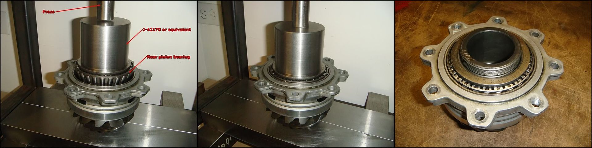
Set J-42170 back into place, again centering it on the bearing so the pinion can pass through the bearing into the tool. Press the rear bearing home, and give it a little extra juice at the bottom to make sure the whole assembly is completely seated. The pinion assembly is almost whole again...
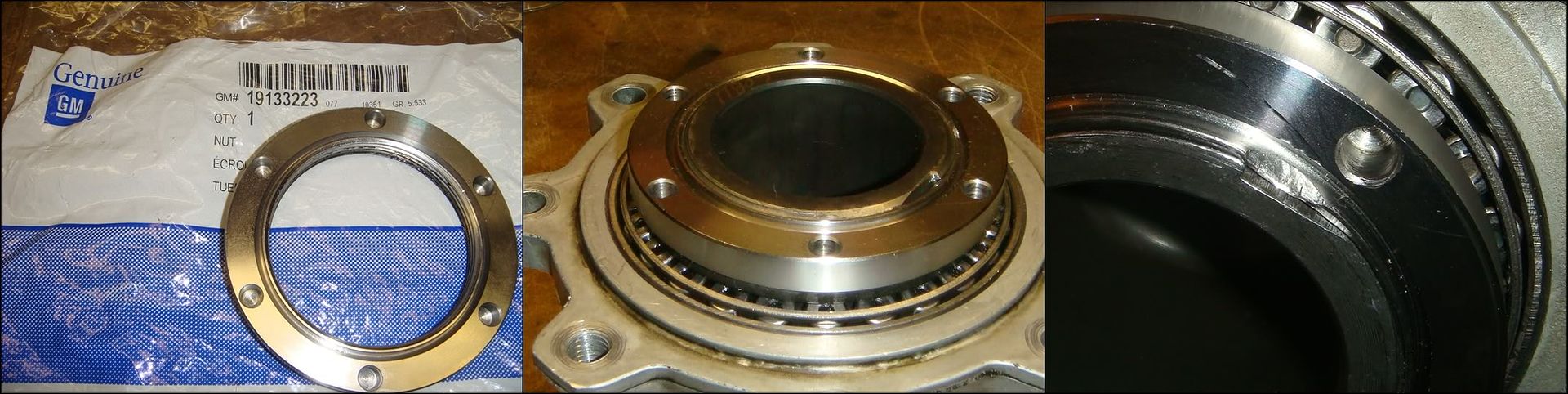
To finish off the pinion assembly, torque the retaining nut back into position. We decided to spend the 30 bucks and get a brand new one, but apparently many builders re-use the old one. If the old stake ends up lining up with the stake on the new pinion, you�ll have to use Loctite instead of peening it as shown above. The torque spec on this nut is 370 lb ft, and we didn�t have a torque wrench that went that high. We probably should have got one from somewhere, but we didn�t. Instead, we used our �� impact driver rated to 400 lb ft. The nut bottoms the bearings out against the preload spacer, so where all that torque is going is beyond me. The stake positively keeps it from backing off. I can�t see why it has to be so tight, but there you have it.
MAIN CASE REASSEMBLY
The LH bearing race presses into the case itself. This is the only major reassembly required to the case. The shims behind this bearing set, among other things, the backlash between the ring and pinion. Setting this is a trial and error process, so this race will probably be in and out a few time before you�re done. That�s ok, as long as you pay attention and press it in square. The bore is aluminum and will get wrecked if you get the race cocked and continue pressing it in.
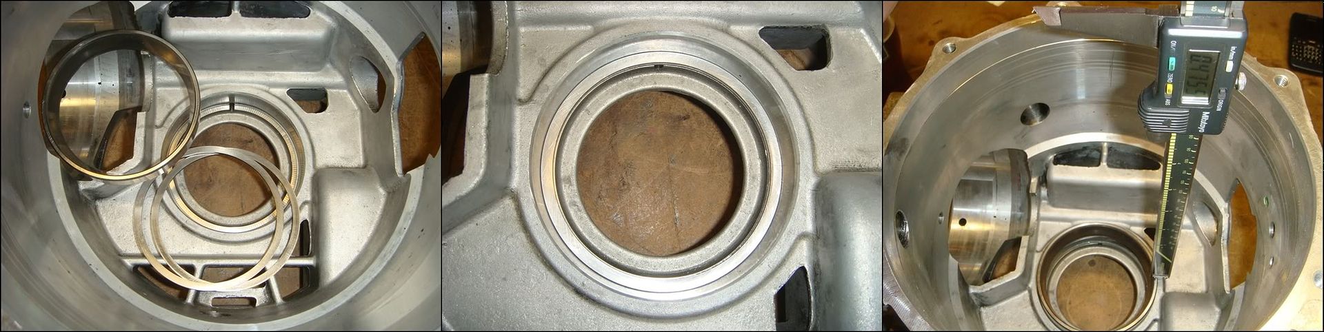
Once you�ve decided on the shims, inspect the bottom of the bore for any burrs or dings and drop the shims into position. Lay the race into the bore and tap it in so its tight and square. Measuring is a little tricky here as the race is deep down inside the case. Reading a rule is hard to do here, so we spared ourselves some grief and used a caliper instead. Whatever you use, measure the height at at least 4 places along the circumference of the race to insure that its sitting level.
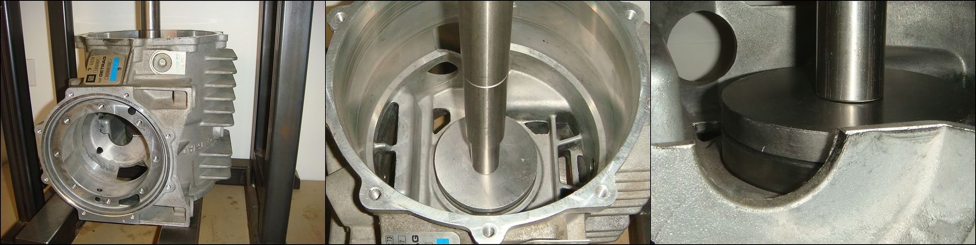
Once its squared away, just place the case into your press and shove the race home. Tool J-42172 is used for this. Make sure the race bottoms out solidly in its bore, and you�re done.
RH COVER REASSEMBLY
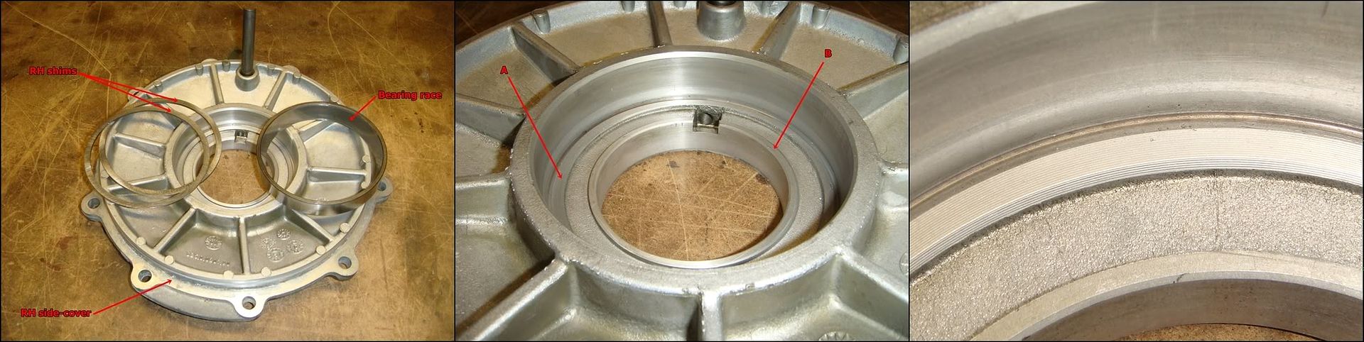
Putting the cover back together is pretty straight forward. Like before, make sure there are no dings on the bottom land the shims sit on, �A� in the photo. The bottom of the bore should be flawless otherwise you�ll have trouble setting the correct preload on the bearings. Likewise, make sure the shims are spotless before dropping them into position. Whatever you do, don�t accidently press the race back in with no shims behind it! The lip marked �B� in the photo will prevent the removal tool from fitting back in under the race. Getting it back out will be a huge pain, and will involve lots of prying and cussing.
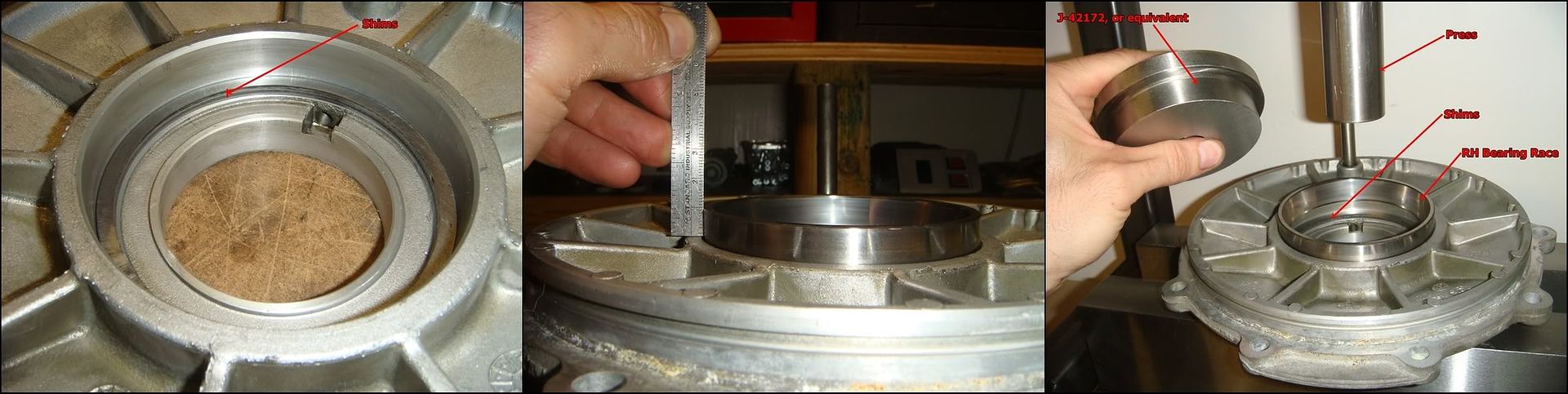
Once the bore is ready to go, drop the calculated thickness of shims in and lay the race at the top of the bore. Like before, tap it in gently all around until it�s sitting square. A short 6� rule is all it takes to make sure it�s not cocked. Now place special tool J-42172 or an appropriately sized bushing driver onto the race�
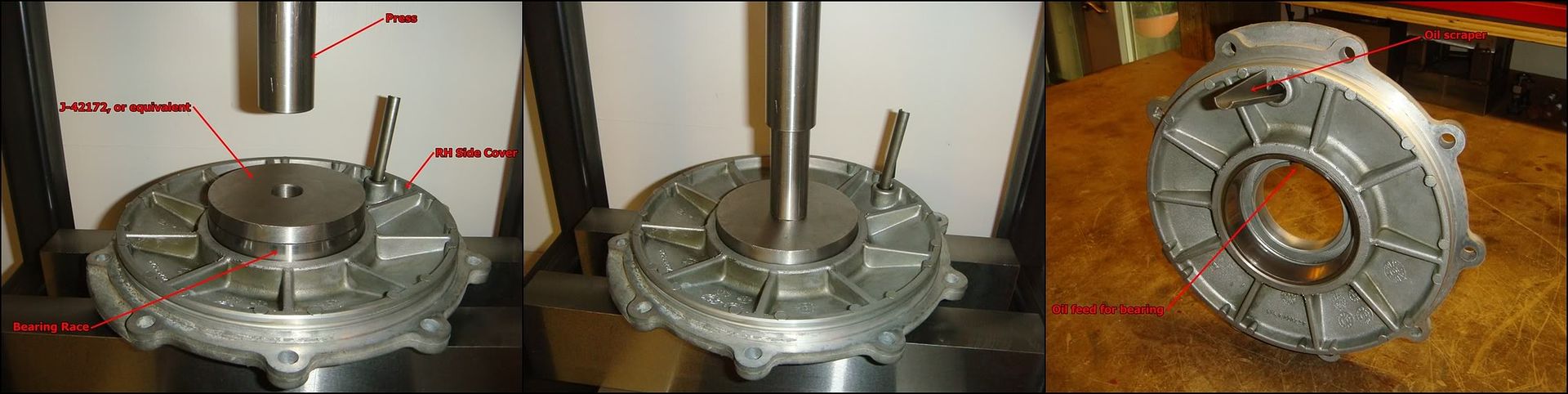
�and press it home. The RH bearing receives oil from this scraper, which skims off some of the windage picked up by the spinning carrier assembly.
LH COVER REASSEMBLY
If the bearing had been left installed, reassembling this cover is just a straightforward case of installing a new oil seal and slipping a new o-ring on. Here�s the full procedure, including installation of the pain-in-the-***-to-remove needle bearing.
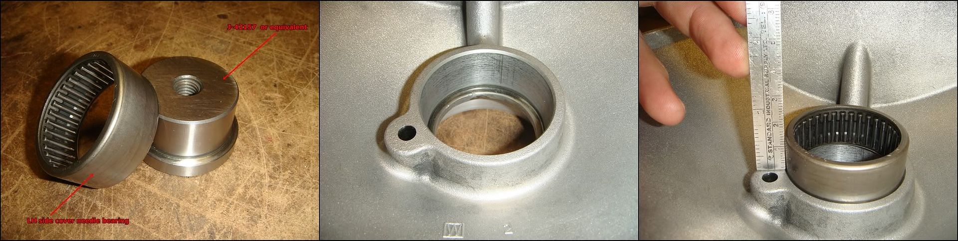
To push this bearing in, you�ll need a driver with a slightly smaller major OD than the bearing. This is because the bearing gets pushed down below the top of the bore. Obviously ,if you have the factory J-tool, you�re already set. This bearing isn�t nearly as critical as the others, but careful installation is still important. As before, check the bore for any obvious burrs or gouges. Once its ready to go, set the bearing into position and adjust it so it sits parallel with the bore.
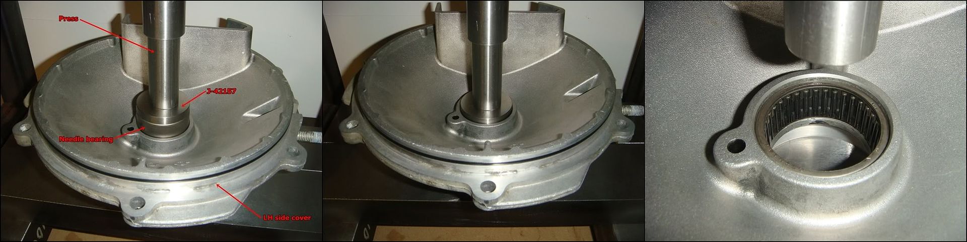
Place J-42157 into the center of the bearing, being careful not to push it out of alignment. Push it down until it just stops moving�feel for it. This bearing has a stamped steel body and will squash if pressed in with too much gusto. Its depth isn�t anywhere near as super-critical as the other bearings, so leave it where it stops. For reference, this bearing is bottomed out in its bore and is about 0.085� below the surface.
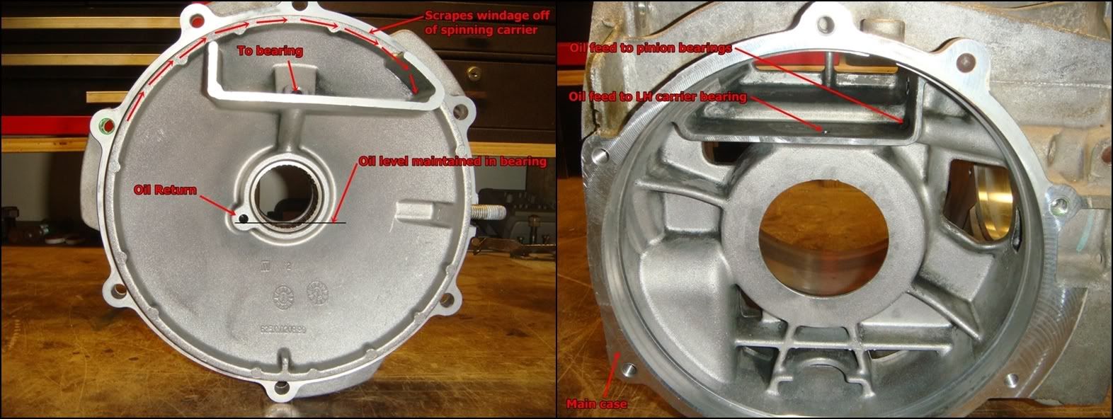
The lube system for this bearing is a sweet example of what I call great engineering. Simple and functional. The box cast into the upper side of the LH cover/main case scrapes oil off the spinning carrier and funnels it directly to the outer side of the bearing through a drilled passage. Some of the oil passes through the bearing while the remainder returns to the sump via the lower drain passage, giving the oil seal a chance to keep it all inside. This system keeps the lower portion of the bearing constantly immersed in oil, high above the oil level mark in the case�without a single moving part.
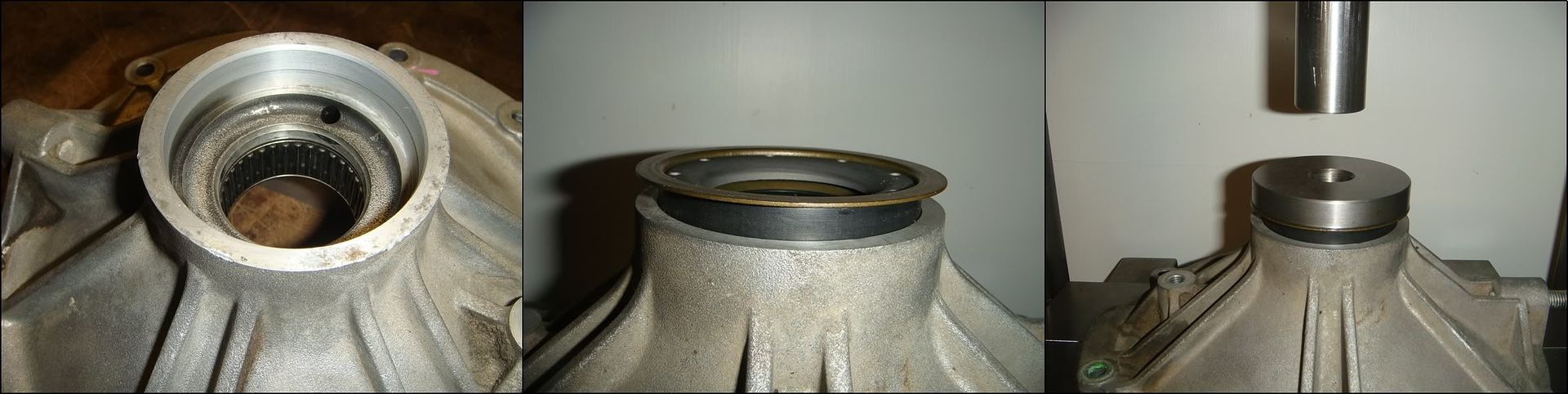
With the roller bearing in place, the rest goes quick and easy. Clean out the outer oil seal bore and then center the seal over it. You can either tap it in carefully with something, or press it in. Tapping works well as long as you pay attention and keep it straight. I prefer to just press them in, since I�m standing next to the press anyway. I use a bushing driver that supports the outer lip well, and fits into the middle without bearing on the seal lip at all. The small hole above the bearing in the first pic drains oil passing thru the bearing, keeping it from backing up behind the seal. Double check that nothing is blocking it.
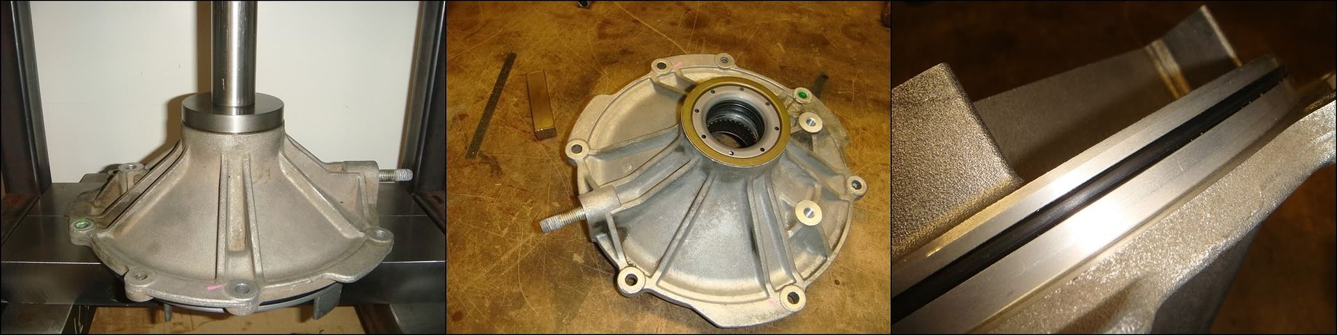
A light squeeze is enough to push the seal home. The steel lip should sit flush with the cover, as shown in the second pic. Slide a new o-ring into the groove, and the cover is done.
And with all that out of the way, the various pieces of this rearend can now be put back together...
CARRIER REASSEMBLY
This picture clearly shows the difference between 2 and 3 series carriers. The 2-series has the ring gear mounted .354� further to the right (passenger side) than the 3-series. A 2-series carrier can still be used with 3.15, 3.42, 3.73, 3.90, or 4.10 ring gears by either using a spacer or a special �thick� ring gear.
Before putting the carrier back together, take some time and inspect the housing for damage. Pay special attention to the areas noted above. Draw a fine file across the ring gear flange to remove any high spots or nicks. If the gear doesn�t pull perfectly flush with the flange, run-out will be excessive and it will be really hard to get a consistent mesh pattern between the ring and pinion. Draw your file across the housing flange where the two housing halves mate, and make sure the housing boss that aligns the halves together is free of nicks and burrs. Don�t go mental with the file�remember you�re working with aluminum here� Draw it flush across these surfaces, and let it tell you how flat they are. If there are no imperfections, the file will slide smoothly across without cutting very much. If any high spots appear, carefully file them flush. Remember that files only cut in one direction; draw it forward across the surface, then lift it up before pulling back. If you are replacing the bearings, pay special attention to the surface in the right-hand photo. If the bearing doesn�t press flush against this surface, the shims selected won�t be correct. They will be correct until the bearing eventually seats itself properly during operation, at which point the perfect gear mesh and bearing preload you set will fly out the window.
If ever there was a good time to slow down and take a deep breath, this is it. The object here is not so much to press the bearing on, but to press it on straight. If you take the time to set the bearing into position level and square before applying pressure from the press, you�re guaranteed to be golden. As you begin pushing the bearing down, watch to see that it �picks up� the boss and goes down straight. Otherwise, you risk �shearing� the aluminum as the bearing goes on crooked. If you damage the housing enough, it won�t hold the bearing tightly enough and might be junk. Honestly, all it takes is a little attention to all but eliminate this outcome. I�m always tempted to put oil on surfaces like this, but with the kind of press fit we�re talking about here, it just squeegees away as the bearing slides down. There�s just no room for it between the shaft and bearing. Maybe it helps, but somehow I doubt it. But if it makes you feel better, go for it.
The cast iron half is next. As above, draw your file across the mating flange and carefully remove any high spots or dings. If the bearing was removed, also dress the flange it seats against.
Like before, take the time and ensure that the bearing is sitting on the end of the shaft properly before hitting it with everything your press has. If you do, the bearing will go on like it had eyes of its own. Otherwise, if it starts going on wonky, you may have to press it off and try again. If this happens, make sure you didn�t leave any burrs or shear marks on the shaft. Make absolutely sure that the bearing has completely bottomed out on the housing�s shoulder
Once the bearings are in place, we can start to load the RH clutch assembly back into the aluminum half of the case. You must decide whether to replace the whole mess, or re-use the original components. Take a close look at every plate and look for signs of overheating or scoring. If the steels (disks without friction material) look discolored or warped, the clutch was probably slipping a lot and should be replaced. If the steels have deep scoring, they should also be replaced. If you decide to replace, you have a few options open to you: you can go with OEM C5 clutches, retro-fit OEM C6 ZO6 clutches which are a direct fit, or go with an aftermarket carbon clutch. Depends entirely on what you�re doing with the car. Remember that some slip is good, necessary actually, if you plan on doing any turning. Two things come together to create slip in these clutches: a grip imbalance between the left and right tires (which is always present), and torque input into the differential. For a given traction imbalance between the two sides, the more torque you try and put down, the more the clutches will slip. For the street, I personally wouldn�t hesitate to use the OEM stuff. If you do a lot of drag racing and don�t want to develop a peg-leg, the aftermarket clutches with stiffer springs might be a better choice�the trade-off will be more shudder during turning as the tires slip before the clutches. The best plan is probably to talk to the people who make this stuff, and don�t spend your money unless you really need it!
Above is a side by side comparison between a factory sintered clutch plate on the right, and an aftermarket carbon clutch plate. The carbon plates have much more grip than the factory piece, and therefore slip less. Here�s what one manufacturer has to say about their product:
CARBONETIC Carbon LSD Features:
� More than twice the differential lock strength of metal LSDs
� High carbon friction material increases the coefficient of friction
� Friction coefficient of metal plate in oil: 0.05 ~ 0.15 vs. carbon plate in oil: 0.25 ~ 0.35
� Low initial drag resistance with reliable performance - surpasses more than 5 times that of metal LSDs
� Acceleration control range in excess of 10 times that of metal LSDs
� Vehicle will remain on track in and out of turns for exacting driving control
� More than 30 times the thermal decomposition resistance of metal LSDs
� Promotes increased driving skill - repeated time attacks or under loads of performance cars
� More than 70 times the service life of metal LSDs
� Virtually noiseless performance
The used factory steel in the first photo above shows minimal scoring, and can be reused without problem. The frictions should be covered with friction material, with no peeling or separation. If the oil grooves are still present, as in the second photo, the disks still have sufficient lining to reuse. The last photo shows the back side of the thick friction plate, where the preload spring bears against it. Because the springs were both broken, the ends started to gouge into the disk surface. No problem�
Any minor glazing or gouging can be removed by drawing the disk over a piece of 400 grit paper laying on a smooth, flat surface. Push down lightly with your fingers, and slide the disk around in a circle until the high spots or glaze go away. Of course, this is only for the steels�don�t start sanding your friction plates like this. The low spots left in the plate above are no problem because there is no sliding taking place on this surface. This plate is splined to the gear, so they always turn together, along with the preload spring in between.
Speaking of pre-load springs, throw them out and get new ones. The factory pieces break all the time. Several aftermarket sources make much better replacements. Don�t even dream of reusing these, even if yours are somehow magically not broken! You�re probably looking at $15 each. The aftermarket pieces generally generate more clamping pressure, which isn�t a bad thing at all if it�s not over done. As mentioned above, some slippage is needed to ensure smooth cornering. From my personal experience, the 35% increase in clamping force generated by the springs sold by DTE had no detrimental effect on my car during turning. That was with the factory clutches. Using them with grippier aftermarket clutches might be a different story, though.
To the best of my knowledge, GM doesn't service the C5 springs separately, so you have to look elsewhere. I went with the springs supplied by DTE. They're pretty expensive, but worth it if they eliminate unnecessary clutch slippage. These pics show a comparison between the factory C5 preload spring on the left, and the DTE piece on the right. Here's what DTE has to say about their product:
Engineered Features of This Product:
-Manufactured of high strength tool steel w/ high carbon-high chromium content
-Forged to increase hardness and material density
-Extremely wear resistant (approx. double that of O.E.)
-Maintains its clamping load force over a greater installed height spread
-No distortion w/ high heat applications
-Temperature resistance of up to 1875* F
-Provides 34% more clutch pack clamping load over O.E. application
-Quiet operation on turns
-Provides increased posi traction operation and clutch pack life
The next component to address is the RH output shaft/side gear. The factory C5 piece is shown in the first photo. As can be seen, it is of one-piece construction. Compare this to the two-piece construction of the C6 ZO6 piece in the second photo. The two designs are directly interchangeable with each other. I have heard that GM used better steel for their C6 output shafts, perhaps due to the chronic breakage problems of the LH C5 shafts. Whether this is actually true or not is unknown. But if you don�t want to take any risks, this is one option. The aftermarket also produces hardened 100M shafts of the two-piece variety for those who have lots of power and money to spare. If going with the two-piece style, ensure that the retaining ring has properly engaged into the shaft and gear, as shown in the third photo.
Now that all the parts decisions have been sorted out, we can reassemble the RH housing. Here, I am reassembling a factory C5 shaft with a factory clutch assembly. Before doing anything, soak the clutch assembly in gear oil. I stole some Tupperware from the wife, which is handy because I can seal it up when I�m done. I�ll pour this oil into the completed diff when I�m done. I�ve used Redline oil in my diff since day one with complete satisfaction. The friction modifiers used always made for happy, quiet clutches. The first drawing shows the order in which the plates must be installed. 1 is the pre-load spring, 2 is the extra thick friction plate, 3 are the friction plates which are splined to the gear, and 4 are the steels, which are driven by the case. I prefer to stack the clutch plates onto the gear assembly first, and then slide the whole thing into the housing. The second photo shows the clutch assembly installed onto the gear, along with the spring. Note the orientation of the spring: �Coning out� towards the clutch.
Now slide the gear/clutch assembly into the housing, jiggling and twisting until the tabs on the steels engage the grooves machined into the inside of the housing. Try not to pull the gear out as you do this or the plates might slide off of it. If this happens, the simplest thing is to just start over again. Trying to line up the splines to the gear and the tabs to the housing at the same time can be pretty frustrating. If everything made it into position properly, there should be just shy of an inch of shaft sticking out the other end. You�ll know for sure when you try and install the two spider gears and cross-shaft�if the shaft won�t go in, something�s wrong. The most likely culprit will be the first friction plate�if it slid off the end of the gear, it probably won�t be lined up on its splines, keeping the rest of the assembly from falling into position.
At this point, the spider gears can be put back in. Check the backsides of the gears and the concave washers for undue wear. Undue wear is a judgment call I guess. Mild scoring like in the second pic is ok, but if it�s munched, replace it. Check all the teeth for problems as well. I guess what I�m saying is actually look at everything closely� don�t just slap it all back together. It�s easy and cheap to fix problems now. Examine the cross pin for any unusual wear. It�s interesting to note that every single lb/ft of torque that you pump into the differential has to pass through this pin before reaching the wheels. If it breaks, you�re screwed. The aftermarket has it covered with high-strength, heat treated alloy pins. I think that they�re about a hundred bucks, which might definitely be worth thinking about if you�re pushing serious power. The stippling on the end of the pin in the third pic is no big deal.
Once you�re happy with the condition of all the parts, begin by inserting the two gears with their respective washers roughly into position. Lube everything with gear oil. Insert J-42162 in between the gears, and place the whole set-up into the press. Start the pin into its bore and slide it in until it stops against the first gear. Using the press, press down on J-42162 enough to allow the pin to pass through the gear. You�ll probably have to wiggle the gear around a little before it lines up with the pin. If you oiled the gears and washers thoroughly, they will stick together as one and you won�t have to worry about the washer going AWOL inside the case. Keep pushing the pin until it passes through the second gear and into the case bore on the other side. The hole on either end of the pin must line up with the corresponding holes in the case. Two of the bolts that hold the two halves of the case together have to pass through the pin before they can thread into position. If you don�t line them up before you release the press, you�ll have to set it all back up in the press again to fix it. A simple way to check that everything is lined up properly is to simply slide a couple of the bolts into position�if they go in, you�re good to go. With that done, the aluminum side of the carrier is done.
Now comes the cast iron half of the carrier. This is the side which contains the troublesome LH output shaft. These shafts have emerged as the definite weak link in these differentials, sometimes breaking with the least provocation. If you have some extra cash layin around, the aftermarket has you covered. Their shafts are made using a super strong alloy known as 300M, and even stronger materials are now available. But of course quality like this costs�expect to pay close to $300 for a 300M long shaft. Another option is an OEM C6 ZO6 shaft, which is considerably stronger than the C5 version. For $60-$70, it won�t break the bank, and will give you some extra peace of mind. The first pic is a quick comparison between the original C5 shaft on the left and the new C6 Z06 shaft on the right. Arrow A points to the strange undercut which leads to most of the failures of this shaft. This was eliminated on the new shaft...as well, the diameter at B was beefed up by about 10%. All other dimensions are the same. If you are changing the shaft, you must swap on the side gear from the old shaft. Simply remove the retaining clip and slide the gear off the old shaft and onto the new. If you were gentle with the clip and didn�t bend the crap out of it, you can reuse it no problem. The CV joint retaining clip on the other end of the shaft needs to be transferred as well. Once the gear is on, the clutch pack can be reassembled. The LH pack goes together in the same fashion as the RH pack. The preload spring, A, goes on first. Orient it so it �cones out� towards the clutch. Next to go on is the extra thick friction plate, B. Position it with the friction material facing away from the gear. The preload spring bears against the steel side of the plate. Now install a steel, D, and then a friction, C. Keep alternating between the two until you end up with something that resembles what�s shown in the third pic. The clutch should end with a steel, which will eventually bear against the cast iron housing.
Now it�s just a matter of jabbing the shaft/clutch back into the housing. Using the holding fixture J-42173 to support the housing makes this a little easier to do. What I did is slide the shaft down into the housing while holding the clutch assembly with my hand. I held onto the clutch until the last moment, and then let it plop down against the housing, making sure the first steel didn�t line up with the grooves in the housing. I then used a scriber to turn the steels until they popped into position, gradually lowering the entire assembly into the housing. Once everything is in place and as far down as it will go, you should see about .4�-.45� between the top of the shaft and the housing mounting flange.
All that�s left to do is join the two halves back together. Just lower the aluminum half down onto the cast iron side, and line them up on locating boss, making sure the screw holes line up. Slide the ten carrier screws in and tighten them down until the heads just start to touch the aluminum. Now, tighten the bolts in small increments, using a criss-cross pattern to ensure the two halves don�t get cocked. The gap between them should stay even all the way around as the two halves come together. Once they bottom out against each other, torque the bolts to 41 lb ft.
Pinion reassembly
If the pinion bearings are being replaced, reassembling the pinion housing with the new races should be the first order of business. This will have to be done before the shim measurements described above can be made. This is because one of the measurement tools (J-42168-2) is positioned within the case by these bearings. As with the carrier bearings, make very certain the land that the race bottoms out on is free from any dings or burrs. If any exist, they will prevent the race from seating properly and result in improper pinion positioning and bearing preload. Smoothing away any high spots can be tricky because it�s so hard to get in there. Go and see what the wife sands her nails with. Mine uses these sandpaper popsicle-stick type things which are absolutely perfect�they can be broken into small pieces and remain flat, unlike sandpaper. Remember that you are working with aluminum here, so take it easy when you remove material�only small amounts of pressure are needed.
Once the housing is ready, lay the race(in this case, the front race) into position. Important: the bearing must be started in the bore square. If it isn�t square, you will almost certainly shear the soft aluminum housing when you try to press it in. If you take your time here and pay attention, I can almost guarantee you won�t have any problems. Tap the race slightly into its bore until it gets tight. It won�t go in very far�just make sure its snug. Use something soft like aluminum or bronze to avoid damaging the race. Take measurements all around as you tap and set the bearing as level as you can. In the second photo, I�ve tapped the bearing snug into its bore with about 12mm poking out, measured all around at 90 degree intervals. The race is now ready to be pressed in. For the front race, the service manual calls for J-42172 as the tool to use here, but you don�t really need anything fancy. I�m using a simple bushing installer, but a flat plate of steel big enough to cover the race would do equally well. When the race is fully installed, it still sticks out of the housing by about .020�, so the tool will never bottom out before the bearing.
Now just set the housing into your press, place J-42172 into position, and push the race down until it positively bottoms out in its bore. If you lined it up nicely, it will slide in smoothly like it had eyes of its own. If it does start going in cockeyed, stop!!! Once it begins to go in wonky, it won�t straighten out on its own, and you might very well wreck the housing if you keep pressing. Press is out, and start again. Check the bore for any damage and carefully smooth it away with some fine (300-400) emery paper.
The rear race is done in exactly the same way. Again, the most important thing to do here is ensure the race is set up level in its bore before pressing it home. Due to the different diameter of this bearing, a different tool is required to press it in. The manual suggests J-42170, but a simple bushing driver, shown in the third pic, will also work.
Once the race is pressed in square and to the bottom of the bore, give it a little extra shove with the press to absolutely ensure its bottomed out. Fully seated, the race will still stick up slightly (maybe 0.020�).
Now we can install the bearing cones back onto the pinion. The larger of the two (the front bearing) goes on first. Everything already written above regarding pressing on bearings applies equally here. Make sure everything is clean and free of burrs and high spots, especially the flat shoulder on the pinion, and the corresponding area on the bearing. The bearing must seat flush here. Set the bearing into position and tap it around until it is sitting level on the pinion. Lay J-42170 or something similar on top of the bearing, making sure that the pinion lines up with the hole in the tool. Press the bearing down until it seats against the pinion�s shoulder. Once it�s down, give it a little extra squeeze to ensure it�s seated. The manual suggests using J-42164 to support the pinion, instead of laying it down directly in the press as shown. That�s up to you�in my humble experience, the press fit on these bearings isn�t too bad�laying the pinion down directly into the press like this probably won�t screw it up too much.
Once the front bearing is in place, slide the preload spacer back on. Make sure it�s the one that belongs with these particular bearings/housing. Then, lower the housing down over the pinion, turning it back and forth to seat it on the front bearing. Lay the rear bearing cone on the end of the pinion and tap it around so it sits level. This is a steel-on-steel press fit, so it�s a little harder to shear anything if the initial line up wasn�t so good�still, set it up nice for no drama.
Set J-42170 back into place, again centering it on the bearing so the pinion can pass through the bearing into the tool. Press the rear bearing home, and give it a little extra juice at the bottom to make sure the whole assembly is completely seated. The pinion assembly is almost whole again...
To finish off the pinion assembly, torque the retaining nut back into position. We decided to spend the 30 bucks and get a brand new one, but apparently many builders re-use the old one. If the old stake ends up lining up with the stake on the new pinion, you�ll have to use Loctite instead of peening it as shown above. The torque spec on this nut is 370 lb ft, and we didn�t have a torque wrench that went that high. We probably should have got one from somewhere, but we didn�t. Instead, we used our �� impact driver rated to 400 lb ft. The nut bottoms the bearings out against the preload spacer, so where all that torque is going is beyond me. The stake positively keeps it from backing off. I can�t see why it has to be so tight, but there you have it.
MAIN CASE REASSEMBLY
The LH bearing race presses into the case itself. This is the only major reassembly required to the case. The shims behind this bearing set, among other things, the backlash between the ring and pinion. Setting this is a trial and error process, so this race will probably be in and out a few time before you�re done. That�s ok, as long as you pay attention and press it in square. The bore is aluminum and will get wrecked if you get the race cocked and continue pressing it in.
Once you�ve decided on the shims, inspect the bottom of the bore for any burrs or dings and drop the shims into position. Lay the race into the bore and tap it in so its tight and square. Measuring is a little tricky here as the race is deep down inside the case. Reading a rule is hard to do here, so we spared ourselves some grief and used a caliper instead. Whatever you use, measure the height at at least 4 places along the circumference of the race to insure that its sitting level.
Once its squared away, just place the case into your press and shove the race home. Tool J-42172 is used for this. Make sure the race bottoms out solidly in its bore, and you�re done.
RH COVER REASSEMBLY
Putting the cover back together is pretty straight forward. Like before, make sure there are no dings on the bottom land the shims sit on, �A� in the photo. The bottom of the bore should be flawless otherwise you�ll have trouble setting the correct preload on the bearings. Likewise, make sure the shims are spotless before dropping them into position. Whatever you do, don�t accidently press the race back in with no shims behind it! The lip marked �B� in the photo will prevent the removal tool from fitting back in under the race. Getting it back out will be a huge pain, and will involve lots of prying and cussing.
Once the bore is ready to go, drop the calculated thickness of shims in and lay the race at the top of the bore. Like before, tap it in gently all around until it�s sitting square. A short 6� rule is all it takes to make sure it�s not cocked. Now place special tool J-42172 or an appropriately sized bushing driver onto the race�
�and press it home. The RH bearing receives oil from this scraper, which skims off some of the windage picked up by the spinning carrier assembly.
LH COVER REASSEMBLY
If the bearing had been left installed, reassembling this cover is just a straightforward case of installing a new oil seal and slipping a new o-ring on. Here�s the full procedure, including installation of the pain-in-the-***-to-remove needle bearing.
To push this bearing in, you�ll need a driver with a slightly smaller major OD than the bearing. This is because the bearing gets pushed down below the top of the bore. Obviously ,if you have the factory J-tool, you�re already set. This bearing isn�t nearly as critical as the others, but careful installation is still important. As before, check the bore for any obvious burrs or gouges. Once its ready to go, set the bearing into position and adjust it so it sits parallel with the bore.
Place J-42157 into the center of the bearing, being careful not to push it out of alignment. Push it down until it just stops moving�feel for it. This bearing has a stamped steel body and will squash if pressed in with too much gusto. Its depth isn�t anywhere near as super-critical as the other bearings, so leave it where it stops. For reference, this bearing is bottomed out in its bore and is about 0.085� below the surface.
The lube system for this bearing is a sweet example of what I call great engineering. Simple and functional. The box cast into the upper side of the LH cover/main case scrapes oil off the spinning carrier and funnels it directly to the outer side of the bearing through a drilled passage. Some of the oil passes through the bearing while the remainder returns to the sump via the lower drain passage, giving the oil seal a chance to keep it all inside. This system keeps the lower portion of the bearing constantly immersed in oil, high above the oil level mark in the case�without a single moving part.
With the roller bearing in place, the rest goes quick and easy. Clean out the outer oil seal bore and then center the seal over it. You can either tap it in carefully with something, or press it in. Tapping works well as long as you pay attention and keep it straight. I prefer to just press them in, since I�m standing next to the press anyway. I use a bushing driver that supports the outer lip well, and fits into the middle without bearing on the seal lip at all. The small hole above the bearing in the first pic drains oil passing thru the bearing, keeping it from backing up behind the seal. Double check that nothing is blocking it.
A light squeeze is enough to push the seal home. The steel lip should sit flush with the cover, as shown in the second pic. Slide a new o-ring into the groove, and the cover is done.
And with all that out of the way, the various pieces of this rearend can now be put back together...
The following 5 users liked this post by Its_Go_Time:
KaiserM715 (10-18-2018),
Linc99 (12-24-2020),
niterydr (03-22-2019),
Pb82 Ronin (01-21-2019),
Pounder (12-16-2015)
11-20-2011, 02:21 PM
#6
Burning Brakes
Thread Starter
If you�ve made it this far, I bet you can go the rest of the way without help. Reassembling the major pieces really is the reverse of taking it all apart.
Oil all the bearings liberally, both the races and the cones. Lower the carrier into the case and seat it into the bearing race by spinning it back and forth a few times. The special GM tool comes in handy for this, but it�s not essential. Once the carrier is back in, don�t forget to install the stud along with the steel reinforcement block.
Re-install the RH cover, and apply a little sealer on the flange if you wish. By now, you should realize that if a sealer is used, it needs to be a thin one. Any thickness added here will throw off the set-up you worked so hard to achieve. The stuff shown below is pretty wicked�its very thin, and never hardens. I actually did a test with the preload tools I made to see what effect this sealer had on the overall width between the bearing bores and, with feeler gauges, it was basically immeasurable. Thick silicone might be a different story though.
Re-install the LH cover. Both left and right covers torque to 18 lb ft. Insert the pinion assembly into position(with its shims) and torque to 18 lb ft. Install the pinion cover with its O-ring.
Done.
Reference information
Bearing Numbers
Side Bearings (L&R):
Timken TS Series bearings
Inner Cones: 387A
Outer Races: 382A
Pinion Bearings:
Front:
Inner Cone: NP568415
Outer Race: NP908986
Rear:
Inner Cone: NP201062
Outer Race: NP101912
Left Side Roller Bearing:
INA HK 4020
GM Part Numbers
Bearings
C5 ZO6 Pinion Housing Assembly (complete with bearings) __________ 88984478
LH Output Shaft Needle Bearing __________ 12458146
Seals
Axle Shaft Seals __________ 88996703
Side Cover O-Rings __________ 89047953
Shafts
LH C6 ZO6 Output shaft __________ 89060119
RH C6 ZO6 Output shaft __________ 89060120
RH C6 ZO6 Side Gear __________ 19180962
RH C6 ZO6 Side Gear Retaining Ring __________ 12458084
Shims
Side shims
1.00mm 0.0393 in __________ 89060047
1.25mm 0.0492 in __________ 89060046
1.30mm 0.0511 in __________ 89060045
1.40mm 0.0551 in __________ 89060044
1.50mm 0.0590 in __________ 89060043
1.60mm 0.0629 in __________ 89060042
1.70mm 0.0669 in __________ 89060041
1.80mm 0.0708 in __________ 89060040
1.90mm 0.0748 in __________ 89060039
2.00mm 0.0787 in __________ 89060038
2.10mm 0.0826 in __________ 89060037
2.20mm 0.0866 in __________ 89060036
Torque Specs (from 2002 GM manual)
Differential Case Bolts __________ 41 lb ft
Differential-to-Transmission Bolts and Nuts __________ 37 lb ft
Drain Plug __________ 26 lb ft
Fill Plug __________ 26 lb ft
Left Side Cover Bolts __________ 18 lb ft
Pinion Housing/Cage Bolts __________ 18 lb ft
Pinion Nut __________ 370 lb ft
Rear Cover Bolts and Stud __________ 89 lb in
Right Side Cover Bolts __________ 18 lb ft
Ring Gear Bolts __________ 144 lb ft
Vehicle Speed Sensor Bolt __________ 9 lb in
Rear Axle Specifications (from 2002 GM manual)
Pinion Rotating Torque __________ 22lb in
Side Bearing Rotating Torque(No Pinion)*
New bearings 15 � 30 lb in
Old bearings 10 � 25 lb in
Ring Gear/Pinion A1 nominal Value (All Axles) __________ 4.055in
Ring Gear/Pinion A2 nominal Value (3 series Axles) __________ 2.58in
Ring Gear/Pinion A2 nominal Value (2 series Axles) __________ 2.93in
Ring Gear/Pinion Backlash __________ 0.0067-0.0082in
* Not from manual
The following 9 users liked this post by Its_Go_Time:
BmoreRnsDeep (04-27-2022),
bobick (11-26-2020),
c5golfguy (06-11-2020),
ericdwong (12-17-2015),
Ghost Knight (04-19-2019),
and 4 others liked this post.
11-20-2011, 06:40 PM
#7
Resident moron


All I can say is, you are my hero. Not only did you figure out how to do it, you fabricated your own tools? Insane.
I just had my rear rebuilt by DTE. I love to do everything myself but I don't think I'll be doing rears anytime soon.
Awesome job though, even just seeing how all the pieces look and work together is great!
Dope
I just had my rear rebuilt by DTE. I love to do everything myself but I don't think I'll be doing rears anytime soon.
Awesome job though, even just seeing how all the pieces look and work together is great!
Dope
11-20-2011, 07:13 PM
#8


Man this thread is awesome! You really did extremely well  . A Mod should sticky this for all the hardwork. It cleared up some questions I had and I'm sure it will clear up a LOT for other people as well. Amazing job man
. A Mod should sticky this for all the hardwork. It cleared up some questions I had and I'm sure it will clear up a LOT for other people as well. Amazing job man

 This is the most sticky-worthy thread I've seen!
11-21-2011, 05:28 PM
This is the most sticky-worthy thread I've seen!
11-21-2011, 05:28 PM
#11
Burning Brakes
Thread Starter
Thanks for that! Hopefully this will give more people the info they need to try this on their own.
Holy crap tho... I didn't realize it would take five minutes for it to load up
Hopefully this will give more people the info they need to try this on their own.Holy crap tho... I didn't realize it would take five minutes for it to load up
11-21-2011, 10:48 PM
#12
Le Mans Master

Member Since: Apr 2005
Location: Scarborough ONTARIO
Posts: 8,077
Likes: 0
Received 3 Likes
on
3 Posts
This was one heck of a project, best of anything tommy prolly did and i was so lucky to be part of it and did on my rear end, i have many blasts at the track including launching at or over 5k rpm, knowing how we build this rear end i was completly confident, clutch and throwout bearing gave up but rear end still held up just fine.
Me being a Auto Technician and Tommy being a Tool & di maker plus a machinist plus a CNC machines extensive knowledge, our zest for making something like this specially Tommy ...result one heck of a project, i would have throw $1000 bucks and let someone do it, but doing ourselves is one great accomplishment.
its 11 pm and iam tired will load my own pictures to add some more fuel and air to already kick azz pictures and explanation provided by Tommy.
This is sticky quality and ton of info, i will be adding more pictures, moderator(s), please make this a sticky thread.
Outstanding post tommy, you are one heck of a person, i thought iam crazy but you are beyond of me.
sami
11-21-2011, 11:42 PM
#13
Burning Brakes
Tommy, after having just finishing my first rear end build up, this is awesome! You have answered all my questions, and given me the confidence to continue with a few more build ups.
I was able to acquire the tools at a reasonable price, but you actually made your own! Hats of to you sir!
Your writing ability is great and I nominate to the title of Tech Contributor.
By all means, this is sticky material!
I was able to acquire the tools at a reasonable price, but you actually made your own! Hats of to you sir!
Your writing ability is great and I nominate to the title of Tech Contributor.
By all means, this is sticky material!
 11-22-2011, 09:27 AM
#15
Tech Contributor
Wow...this is one of the best tech threads I've seen!!!
For sure Its_Go_Time, you should get a "Tech Contributor" tag and have this thread stickied!
Thanks for all the effort. Guys like you make this Forum great.
For sure Its_Go_Time, you should get a "Tech Contributor" tag and have this thread stickied!
Thanks for all the effort. Guys like you make this Forum great.
11-23-2011, 09:21 PM
#17
Burning Brakes
Thread Starter
Thank you all for the kind words! 
Sami, ur a funny guy. We did all of this, and now you decide to go with a supercharger??? Now its bye bye to the 4.10s and hello to the original 3.42s
Sami, ur a funny guy. We did all of this, and now you decide to go with a supercharger??? Now its bye bye to the 4.10s and hello to the original 3.42s
10-29-2015, 09:50 AM
#19
Melting Slicks


Wow epic journey extreme learning curve and taking your time to share with us makes it double undertaker cangrats definitely will be helpful to me thanks, David.
12-16-2015, 03:36 PM
#20
Former Vendor

First off, Its Go Time - fantastic write up.
Today we received a phone call at the shop wanting to pick up the preload spring and I thought it would be worth posting a link to the item in this thread so we can better serve anyone looking to do this write up.
LINK:
http://shop.hoosierpe.com/HD-Conical...?categoryId=-1
Again, good job on your journey and giving the community a great write up to follow along.
Cheers,
Jason Massey
General Manager