
How-To repair EBCM avoiding costly repairs through ABSfixer or Fleabay
 10-06-2012, 02:52 PM
#181
Tech Contributor


Member Since: Dec 1999
Location: Anthony TX
Posts: 32,736
Received 2,180 Likes
on
1,583 Posts
CI 6,7,8,9,11 Vet
St. Jude Donor '08

You need to actually read the contact resistance. Should be zero ohms when the relay is energized.. If the relay has contacts in both energized and deenergized... both should read zero ohms in their prospective SHUT contact condition.
When the relay is reinstalled, read the actual resistance thru the relay by attaching the ohm meter leads somewhere on the circuit board other than right on the relay feed thru lugs.
If the relay is good and you still have 1214, the relay isn't getting power when the module is reinstalled on the BPMV.
BC
BC
 10-06-2012, 08:01 PM
#182
Former Vendor
Member Since: Nov 2005
Location: Ossining New York
Posts: 11,792
Received 243 Likes
on
183 Posts
St. Jude Donor '07-'08-'09-'10-'12-'13-'14

QUOTE "The points looked good"
You need to actually read the contact resistance. Should be zero ohms when the relay is energized.. If the relay has contacts in both energized and deenergized... both should read zero ohms in their prospective SHUT contact condition.
When the relay is reinstalled, read the actual resistance thru the relay by attaching the ohm meter leads somewhere on the circuit board other than right on the relay feed thru lugs.
If the relay is good and you still have 1214, the relay isn't getting power when the module is reinstalled on the BPMV.
BC
BC
RESISTANCE..... What's that!?!?!?!?!
DEFINITION: [ri-zis-tuhns] noun
1. the act or power of resisting, opposing, or withstanding.
2. the opposition offered by one thing, force, etc., to another.
3. Corvette Forum POSTS where people give Chuck CoW a hard time
about the AMAZING CoW BOOSTER!
Come on Billy! Just get out your electron microscope and look at the contacts
close up..... No need for an antiquated OHM meter.

Chuck CoW
10-06-2012, 08:47 PM
#183
Tech Contributor
Member Since: Dec 1999
Location: Anthony TX
Posts: 32,736
Received 2,180 Likes
on
1,583 Posts
CI 6,7,8,9,11 Vet
St. Jude Donor '08
Chuck
Sometimes it a WHOLE lot easier and quicker just to throw the FLUKE on the circuit and say YEA or NAY!
BC
Sometimes it a WHOLE lot easier and quicker just to throw the FLUKE on the circuit and say YEA or NAY!
BC
10-08-2012, 08:46 PM
#184
Racer

Thank you to the op Bill Cow and everyone else who worked on this thread. I pulled mine and redid the board with ALMOST complete success. Everything works great but when I was putting the unit back in I dropped one of the torx screws down the sewer next to my driveway. (dumb things people do makes this forum so much fun!) My question then is does anyone know what the size of the screws are that secure the unit to the BCM? I want to see if I can pick one up at lowes or home depot rather than pay the dealer.
10-08-2012, 08:51 PM
#185
Cruising

Member Since: Sep 2012
Posts: 10
Likes: 0
Received 0 Likes
on
0 Posts
Thank you to the op Bill Cow and everyone else who worked on this thread. I pulled mine and redid the board with ALMOST complete success. Everything works great but when I was putting the unit back in I dropped one of the torx screws down the sewer next to my driveway. (dumb things people do makes this forum so much fun!) My question then is does anyone know what the size of the screws are that secure the unit to the BCM? I want to see if I can pick one up at lowes or home depot rather than pay the dealer.
10-08-2012, 09:01 PM
#186
Cruising
Member Since: Sep 2012
Posts: 10
Likes: 0
Received 0 Likes
on
0 Posts
Thanks for all the help,
Bill, I removed the relay and have one being shipped to me, just hope it is the correct relay ( post 180 ) I have removed the battery and checking my grounds again to be sure all is making good contact. Checked all fuses, Battery is new and tests great, no sign of any bad contact. Should have the relay installed on Thursday.
Thanks
10-09-2012, 02:10 PM
#187
Racer
For anyone else who may be looking the screws are GM part number 11561602. they are 4x0.7x22 in size. My dealership does not have them so I'm off the home depot.
10-28-2012, 10:48 PM
#188

thanks for the thread i finaly fixed my ebcm traction control wors and abs light is off i had to pull the ebcm module and solder the relay post not enough solder from factory works fine thanks for taking the time to post info as it was a big help--now if i could only get my dic buttons to work
11-05-2012, 08:06 PM
#189
Melting Slicks

Member Since: Mar 2006
Location: Piedmont Va
Posts: 3,456
Received 100 Likes
on
85 Posts
St. Jude Donor '11-'12-'13,'19-'20
Thanks Guys! This worked for me. I also spent some time testing all components that could be accessed without removing any. I checked that diodes and resistors weren't fried, and that the caps charged and discharged. Re-soldered pretty much all accessible points. Re-sealed it, installed it in the car and cleaned my chassis grounds! Works great and my car now has 0 codes!  Thanks to all who contributed to this thread!
Thanks to all who contributed to this thread!

 11-16-2012, 04:33 PM
#191
Instructor
Member Since: Dec 2002
Location: North Richland Hills TX
Posts: 157
Likes: 0
Received 0 Likes
on
0 Posts
Another one fixed, just pulled EBCM this morning and resoldered relay. All codes erased and ABS etc is all operational. Thank you all for a great thread.
11-28-2012, 09:54 AM
#192
Drifting

For people finding this thread forthe fix I recently done this job to my 2001 and have a couple ideas that made the job a little easier. Removing the top radiator hose made access to the EBCM a lot easier to get off.
And as far as separating the EBCM halfs that some have trouble with, if you run a drill bit into the hole that is filled with silicon it will clean it out so you can run a screw into it or like I did us a small punch and tap it apart.
And as far as separating the EBCM halfs that some have trouble with, if you run a drill bit into the hole that is filled with silicon it will clean it out so you can run a screw into it or like I did us a small punch and tap it apart.
11-28-2012, 07:20 PM
#193
Instructor
Great thread. Planning on doing mine soon.
I have another question: My ABS light & traction control light were on when I bought my car. I had other issues to take care of that were more pressing (rear wheel bearing, ac pullies, tires, yada, yada, yada...) Was going to send to abs fixer. But this repair was a ways down on the list...
After a couple of months, the traction control light went out... ABS light is still on & still throws the code.
Has this happened to anyone else??? Has anyone had to repair the light? How do you fix this?
Thanks
11-28-2012, 07:26 PM
#194
Heel & Toe
Member Since: Mar 2012
Location: Arvada Colorado
Posts: 17
Likes: 0
Received 0 Likes
on
0 Posts
What are you trying to de-solder? The "fix" is to re-solder the 5 connections of the relay to the printed circuit board. This is done with a small soldering iron and just a drop of solder at each joint.
If your relay needs to be replaced, then you will have to de-solder the relay. This can be done with copper braid. It's placed between the soldering iron tip and the joint. When heated, the old solder flows into the copper braid. I can send you some if you need it. It will only take a couple of inches of it.
Rich
11-28-2012, 08:05 PM
#195
Tech Contributor
Member Since: Dec 1999
Location: Anthony TX
Posts: 32,736
Received 2,180 Likes
on
1,583 Posts
CI 6,7,8,9,11 Vet
St. Jude Donor '08
Great thread. Planning on doing mine soon.
I have another question: My ABS light & traction control light were on when I bought my car. I had other issues to take care of that were more pressing (rear wheel bearing, ac pullies, tires, yada, yada, yada...) Was going to send to abs fixer. But this repair was a ways down on the list...
After a couple of months, the traction control light went out... ABS light is still on & still throws the code.
Has this happened to anyone else??? Has anyone had to repair the light? How do you fix this?
Thanks
I have another question: My ABS light & traction control light were on when I bought my car. I had other issues to take care of that were more pressing (rear wheel bearing, ac pullies, tires, yada, yada, yada...) Was going to send to abs fixer. But this repair was a ways down on the list...
After a couple of months, the traction control light went out... ABS light is still on & still throws the code.
Has this happened to anyone else??? Has anyone had to repair the light? How do you fix this?
Thanks
BC
11-28-2012, 09:57 PM
#196
Instructor
11-28-2012, 10:16 PM
#197
Instructor
Yuk. I havent pulled codes in a while... Looks like I have more work to do... Crap.
 11-28-2012, 11:01 PM
#198
Tech Contributor
Member Since: Dec 1999
Location: Anthony TX
Posts: 32,736
Received 2,180 Likes
on
1,583 Posts
CI 6,7,8,9,11 Vet
St. Jude Donor '08
11-30-2012, 06:30 PM
#199
Instructor

Another one fixed with help from the forum. I ran a screw through the hole to separate the unit, but found it hit the circuit board. I ran a smaller diameter punch through the hole at a slight angle to clear the circuit board, and that worked. Soldered the relay connections and all was good.
After clearing codes, found the steering wheel sensor was also bad. Pulled steering column with instructions found in the forum to replace the sensor, and now no codes.
After clearing codes, found the steering wheel sensor was also bad. Pulled steering column with instructions found in the forum to replace the sensor, and now no codes.
01-01-2013, 11:52 AM
#200
Another apparently successful fix here for my '01. I found and fixed the same cold solder joints and tested the unit last night. 1214 code appears to be gone.
The repair would have been impossible without the help of this thread. Even my wife feigned some appreciation for the savings this enabled!
I just wanted to throw out a few pointers that would have helped me going into this...
1. I probably missed it somewhere, but I didn't realize that the cold solder joints and the relay were one in the same. The pics of the culprit connections were those for the relay. Aha!
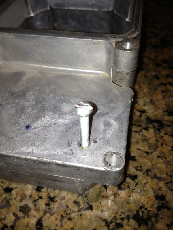
2. I also had a little trouble getting the sealed cover off the unit. I tapped in a couple of thin screws and wound up with bent screws and a lot of apprehension that I'd been pounding on the circuit board. I took a break and came to the realization that steady pressure applied to the cover would be better than pounding on it. I found a scrap 1 1/2" long screw that is about 2.5mm wide (I think it's a number 8 size) and pushed it into the hole until I reached a hard stop (about 3/4"). The hole then easily self-threaded and I advanced the screw until it was tight against the cover. I then heated the corner of the unit next to the screw hole with my heat gun to help loosen the seal. After 3-4 cycles of heating and then advancing the screw a 1/4 turn, the seal broke open enough to easily fit a large flat head screwdriver into the gap. Work the screw driver around the unit and the seal easily breaks.
1 1/2" screw:
2. The access hole passes through a channel in the corner of the unit and, as advertised earlier by others in the thread, does completely protect you from hitting the circuit board. That really had me worried until I got the unit open. Here's pic to show the protective channel (with screw inserted from the inside of the unit):
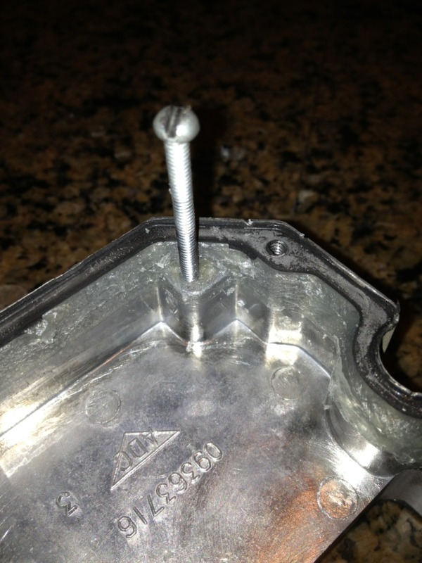
3. The edge of the cover is sealed with a black sealant that is easily broken with the process I outlined in #1. Once you get past the seal, though, there's 1/2" of silicone that anchors the unit to the cover. You can see it well in the pic above. It'll take a little more finesse to get that separated when you remove the cover.
Thanks again for all that have contributed throughout the thread - invaluable info!!!
The repair would have been impossible without the help of this thread. Even my wife feigned some appreciation for the savings this enabled!
I just wanted to throw out a few pointers that would have helped me going into this...
1. I probably missed it somewhere, but I didn't realize that the cold solder joints and the relay were one in the same. The pics of the culprit connections were those for the relay. Aha!
2. I also had a little trouble getting the sealed cover off the unit. I tapped in a couple of thin screws and wound up with bent screws and a lot of apprehension that I'd been pounding on the circuit board. I took a break and came to the realization that steady pressure applied to the cover would be better than pounding on it. I found a scrap 1 1/2" long screw that is about 2.5mm wide (I think it's a number 8 size) and pushed it into the hole until I reached a hard stop (about 3/4"). The hole then easily self-threaded and I advanced the screw until it was tight against the cover. I then heated the corner of the unit next to the screw hole with my heat gun to help loosen the seal. After 3-4 cycles of heating and then advancing the screw a 1/4 turn, the seal broke open enough to easily fit a large flat head screwdriver into the gap. Work the screw driver around the unit and the seal easily breaks.
1 1/2" screw:
2. The access hole passes through a channel in the corner of the unit and, as advertised earlier by others in the thread, does completely protect you from hitting the circuit board. That really had me worried until I got the unit open. Here's pic to show the protective channel (with screw inserted from the inside of the unit):
3. The edge of the cover is sealed with a black sealant that is easily broken with the process I outlined in #1. Once you get past the seal, though, there's 1/2" of silicone that anchors the unit to the cover. You can see it well in the pic above. It'll take a little more finesse to get that separated when you remove the cover.
Thanks again for all that have contributed throughout the thread - invaluable info!!!
Last edited by ajchance; 01-01-2013 at 11:58 AM.