
Cam/Header/CAI and other misc items install
 05-17-2010, 07:36 PM
#41
Instructor

Thread Starter
Member Since: Feb 2009
Location: Lockport IL
Posts: 177
Likes: 0
Received 0 Likes
on
0 Posts
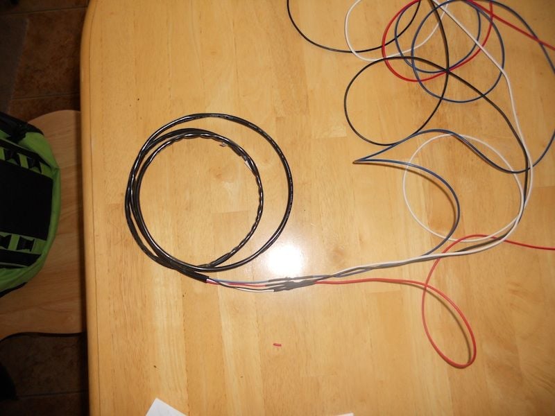
Here are my pics of the AEM UEGO install. The UEGO is up and running, but I still have some things to complete, so this install is still progessing and a couple of things still needs to be complete before its complete.
UPDATE: I finally have a set of headers coming in, probably later this week, so I'll get the bung installed on the drive side header and then complete the UEGO install.
Step1)So the AEM UEGO needs a 10-18V power source and a ground for this install, and it has a couple more wires for other use. Like the blue wire can be used for logging to a hyperterminal or any AFR software. So, I had to think about what I'm going to use as my power and ground source, so I reverted to the forums and got my question answered by lucky131969(Thanks lucky ). Below is the schematic of were its going:
I'll utilize the YEL and BLK wire for power and ground, I'm also going to change out the 20A fuse to a 10A to meet AEM UEGO requirements.

Step2) Pic of where the C206 connector is at: (Now you don't have to take out the fuse box like I did, I was trying to look for it(trace it), but should've looked elsewhere prior to taking it out)

Step3)For the next step, I essentially took the whole interior apart, and I followed the "How to install a HUD" guide to complete this step. This is the only way I knew, to route the wires from the UEGO unit to connector C206. This is what the car looked like after I took the interior apart The arrows show the path I'll be taking the cables to the passenger side. I even zip tied to what looked like air tubes)

Step4) In order for the cables to reach, you'll have to stop at a local hardware store and buy 5 foot long wires, for the stock wires couldn't reach to connector C206. I also used shrink tubes to make thing look a little cleaner(wrap it with electrical tape and your ready to route).
Step5) Once you have the cables routed, unplug connector C206, and you'll see three wires(yellow, black, and orange) all taped together. I wired red(UEGO) to the YLW, and black(UEGO) to the BLK wire and shrink tubed them. I also put electrical tape around the orange wire and then taped it to the other two wires(I also plugged it in and turn the key to either ACC/ON to test to see if it worked):

Step6)Now its time for the bung connector. You'll have to drill a 1" hole in your firewall, and I've decided to drill right below the hood release. NOTE: To drill, I just unscrewed the driver wheel well to gain access for drilling. Also, for now, I left the bung connector sit on top of my motor until I get my exhaust so I can finish the routing. Once your down there you can imagine how to route it and the wires can be zipped tie to existing wires so it doesn't hit anything else.
Driver Wheel Well:

Driver interior under the hood release cables:

Step7)Its time to drill the pod into the pillar. For this I used painters tape to hold the pod onto the pillar and then drilled by following manufactures specs for the plugs, and drilled a 1" hole for the wires.


Step8) You can now start buttoning everything back up. Once you have your dash in, you can install the drivers A-Pillar and plug in the UEGO and your ready to go. I'll be taking more pictures once I finishing the rest of the install, like the exhaust and the blue data cable.
Partially Finished pics of the install:


UPDATE: I finally have a set of headers coming in, probably later this week, so I'll get the bung installed on the drive side header and then complete the UEGO install.
Step1)So the AEM UEGO needs a 10-18V power source and a ground for this install, and it has a couple more wires for other use. Like the blue wire can be used for logging to a hyperterminal or any AFR software. So, I had to think about what I'm going to use as my power and ground source, so I reverted to the forums and got my question answered by lucky131969(Thanks lucky
). Below is the schematic of were its going:I'll utilize the YEL and BLK wire for power and ground, I'm also going to change out the 20A fuse to a 10A to meet AEM UEGO requirements.
Step2) Pic of where the C206 connector is at: (Now you don't have to take out the fuse box like I did, I was trying to look for it(trace it), but should've looked elsewhere prior to taking it out)
Step3)For the next step, I essentially took the whole interior apart, and I followed the "How to install a HUD" guide to complete this step. This is the only way I knew, to route the wires from the UEGO unit to connector C206. This is what the car looked like after I took the interior apart
The arrows show the path I'll be taking the cables to the passenger side. I even zip tied to what looked like air tubes)Step4) In order for the cables to reach, you'll have to stop at a local hardware store and buy 5 foot long wires, for the stock wires couldn't reach to connector C206. I also used shrink tubes to make thing look a little cleaner(wrap it with electrical tape and your ready to route).
Step5) Once you have the cables routed, unplug connector C206, and you'll see three wires(yellow, black, and orange) all taped together. I wired red(UEGO) to the YLW, and black(UEGO) to the BLK wire and shrink tubed them. I also put electrical tape around the orange wire and then taped it to the other two wires(I also plugged it in and turn the key to either ACC/ON to test to see if it worked):
Step6)Now its time for the bung connector. You'll have to drill a 1" hole in your firewall, and I've decided to drill right below the hood release. NOTE: To drill, I just unscrewed the driver wheel well to gain access for drilling. Also, for now, I left the bung connector sit on top of my motor until I get my exhaust so I can finish the routing. Once your down there you can imagine how to route it and the wires can be zipped tie to existing wires so it doesn't hit anything else.
Driver Wheel Well:
Driver interior under the hood release cables:
Step7)Its time to drill the pod into the pillar. For this I used painters tape to hold the pod onto the pillar and then drilled by following manufactures specs for the plugs, and drilled a 1" hole for the wires.
Step8) You can now start buttoning everything back up. Once you have your dash in, you can install the drivers A-Pillar and plug in the UEGO and your ready to go. I'll be taking more pictures once I finishing the rest of the install, like the exhaust and the blue data cable.
Partially Finished pics of the install:
Last edited by mstrnad; 05-17-2010 at 07:59 PM.
 05-18-2010, 11:17 AM
#42
AKA "The CLOWN"

Member Since: Feb 2010
Location: Chicago South Suburbs
Posts: 6,261
Likes: 0
Received 12 Likes
on
12 Posts

Very nice mike. Sounds dam good. I already bought my 5/16 rod to hold up my lifters..LOL The wife said what are them for, and i told her. She said dan, you better not have bought that cam kit yet. You promised me that you would take me on vacation first.Which i did. But she dont know the little stach of $ i got saved for it. HEHE. I cant WAIT......
 05-18-2010, 11:24 AM
#43
AKA "The CLOWN"
Member Since: Feb 2010
Location: Chicago South Suburbs
Posts: 6,261
Likes: 0
Received 12 Likes
on
12 Posts
Sounds pretty good, it will get alot better when you get those LT's on, when are you planning on compleation, we need to get a few guys in Chicago south burbs together for a nice cruise and some cold ones, PM me with your contact info and we can hook up! best of luck on your finish!
05-18-2010, 05:27 PM
#44
Instructor
Thread Starter
Member Since: Feb 2009
Location: Lockport IL
Posts: 177
Likes: 0
Received 0 Likes
on
0 Posts
Sounds pretty good, it will get alot better when you get those LT's on, when are you planning on compleation, we need to get a few guys in Chicago south burbs together for a nice cruise and some cold ones, PM me with your contact info and we can hook up! best of luck on your finish!
05-18-2010, 07:03 PM
#45
Supporting Tuner


Sweet!


 05-19-2010, 04:48 PM
#48
Instructor
Thread Starter
Member Since: Feb 2009
Location: Lockport IL
Posts: 177
Likes: 0
Received 0 Likes
on
0 Posts

 05-26-2010, 09:41 AM
#50
Instructor
Thread Starter
Member Since: Feb 2009
Location: Lockport IL
Posts: 177
Likes: 0
Received 0 Likes
on
0 Posts
05-26-2010, 12:37 PM
#51
Safety Car

Member Since: Mar 2005
Location: Madison Wisconsin
Posts: 3,639
Likes: 0
Received 8 Likes
on
6 Posts
St. Jude Donor '08
Enjoyed reading your thread. I just had cam/headers installed on my 2000 FRC. Looking forward to seeing/hearing how yours turns out after the tune. 
06-01-2010, 07:46 PM
#52
Instructor
Thread Starter
Member Since: Feb 2009
Location: Lockport IL
Posts: 177
Likes: 0
Received 0 Likes
on
0 Posts
Ok...the tune is in. Based on the graph I got 416hp/360ft-lb, WC corrected. Overall, I'm pretty happy about the numbers. I'm going to take it back to get the tuning finalized sometime later this month. Sorry about the pic, I had to take the picture on an angle so the flash doesn't white it out.

PS...I have a bunch of pics to add to this thread that will pretty much finish it.
PS...I have a bunch of pics to add to this thread that will pretty much finish it.
06-01-2010, 08:48 PM
#53
Drifting

Ok...the tune is in. Based on the graph I got 416hp/360ft-lb, WC corrected. Overall, I'm pretty happy about the numbers. I'm going to take it back to get the tuning finalized sometime later this month. Sorry about the pic, I had to take the picture on an angle so the flash doesn't white it out.
PS...I have a bunch of pics to add to this thread that will pretty much finish it.
PS...I have a bunch of pics to add to this thread that will pretty much finish it.
Do you know what kind of dyno it was when they tuned it.
Last edited by 20vette0107fatboy; 06-01-2010 at 08:49 PM. Reason: For got a ques.
06-16-2010, 04:36 PM
#55
Instructor
Thread Starter
Member Since: Feb 2009
Location: Lockport IL
Posts: 177
Likes: 0
Received 0 Likes
on
0 Posts
Very very soon. I'm taking car back this week to the tuner to fix the idle. Though, I'll take a video of it tonight and put it up. I just love the sound when it idles correctly. Talk about turning heads during a stop light.
Also I had purchased and put on the XSPower LT headers. I was getting sick of running the car without cats, and the wideband bung placement is great.
06-17-2010, 02:04 AM
#59
Instructor
Thread Starter
Member Since: Feb 2009
Location: Lockport IL
Posts: 177
Likes: 0
Received 0 Likes
on
0 Posts