
Help! Changed oil sender, now water temp spiked and car runs terrible
 08-19-2009, 05:53 PM
#1
Advanced

Thread Starter
Member Since: Sep 2007
Location: CA
Posts: 83
Likes: 0
Received 0 Likes
on
0 Posts

I also posted in the oil pressure sender sticky
I read the first 14 pages of the oil pressure sender sticky and figured I had enough info to do the cut-a-hole method. Went to Kragen and came home with a nice brass sender and a lifetime warranty. I'm thinking sweet, this is going better than expected already.
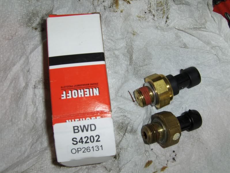
I cut the hole, r&r'd the sensor without issue, and put it back together.
Here's the problem......which has me in panic mode!
After I fired the car up the oil pressure went to 43psi and is working great. Problem is, the car ran for about 6 seconds before the water temp gauge pegged out and the car started missing/running like crap. The car had only run for about seconds so I know it's not actually hot. I'm pretty sure I plugged the pcv line back in correctly at the splice above the oil sender, so I have no idea why it would have a miss? What in the world is the problem?
I read the first 14 pages of the oil pressure sender sticky and figured I had enough info to do the cut-a-hole method. Went to Kragen and came home with a nice brass sender and a lifetime warranty. I'm thinking sweet, this is going better than expected already.
I cut the hole, r&r'd the sensor without issue, and put it back together.
Here's the problem......which has me in panic mode!
After I fired the car up the oil pressure went to 43psi and is working great. Problem is, the car ran for about 6 seconds before the water temp gauge pegged out and the car started missing/running like crap. The car had only run for about seconds so I know it's not actually hot. I'm pretty sure I plugged the pcv line back in correctly at the splice above the oil sender, so I have no idea why it would have a miss? What in the world is the problem?

 08-19-2009, 06:07 PM
#5
Melting Slicks


Member Since: Feb 2007
Location: Indian Rocks Beach FL
Posts: 3,266
Likes: 0
Received 7 Likes
on
7 Posts
St. Jude Donor '08-'09-'10
You don't have to have a scanner:
To enter the Diagnostic Display function perform the following steps in order:
1. Turn ON the ignition switch, engine OFF.
2. Press the RESET button to acknowledge any warning messages present.
3. Press the OPTIONS button on the Driver Information Center (DIC) and hold.
4. While holding the OPTIONS button press the FUEL button 4 times within a 10 second period.
5. System will first enter automatic display mode followed by the manual display mode.
The automatic display feature allow you to read each module DTC display function in an automatic display sequence. Each system module DTC will be displayed for 3 seconds followed by a 1 second pause before the next DTC is displayed in an automatic sequence. If no DTC information is sent to the IPC from the system currently displayed on the IPC, the IPC will display NO CODES for that system. At any time during the automatic display function, the manual display feature can be activated by pressing any button on the DIC except the E/M 5 button. The E/M 5 button is used to completely exit the DIAGNOSTICS mode at any time. If there is a communications problem between any system, the IPC will display NO COMM when the IPC is trying to communicate with that system. When all DTCs have been displayed for all systems, the IPC will display NO MORE CODES for 2 seconds then will enter the manual display mode, waiting for manual mode operation.
The manual display feature allows you to manually select each module DTC display function. The manual mode will automatically be entered after the automatic DTC display sequence is complete, or can be entered at any time during the automatic mode by pressing any button on the DIC except the E/M 5 (E/M 5 button is used to exit the DIAGNOSTIC mode at any time). When the manual mode is selected, the IPC will display the MANUAL DIAGNOSTICS mode message for 2 seconds, or until any button on the DIC except the E/M 5 is pressed. After the MANUAL DIAGNOSTICS mode message is displayed, the IPC will display the first system abbreviation and quantity of codes stored for that system, then the IPC will wait for further instructions. The buttons on the DIC provide the following functions when operating the on-board diagnostic feature in the manual mode:
DIC Button Function
FUEL 1 Previous DTC
GAGES 2 Next DTC
TRIP 3 Previous System
OPTIONS 4 Next System
E/M 5 Exit Diagnostics
RESET Clear DTCs
08-19-2009, 06:31 PM
#6
Advanced
Thread Starter
Member Since: Sep 2007
Location: CA
Posts: 83
Likes: 0
Received 0 Likes
on
0 Posts
Thanks for the info....here they are
PCM
PO118 H C
PO357 H
AO-LDCM
B2282 H
B2284 H
B2278 H
U1064 H
A1 RDCM
B2283 H
B2285 H
B2265 H
U1064 H
BO-RFA
U1096 H
U1064 H
U1016 H
C2120 H C
PCM
PO118 H C
PO357 H
AO-LDCM
B2282 H
B2284 H
B2278 H
U1064 H
A1 RDCM
B2283 H
B2285 H
B2265 H
U1064 H
BO-RFA
U1096 H
U1064 H
U1016 H
C2120 H C
08-19-2009, 06:47 PM
#7
Tech Contributor
Did you disconnect the battery ? First, see if you can clear all the codes. If they return, disconnect the ECT and see what the gauge reads.
08-19-2009, 07:02 PM
#8
Tech Contributor
Member Since: Dec 2006
Location: Van Buren Arkansas
Posts: 10,962
Likes: 0
Received 26 Likes
on
25 Posts
Wounded Warrior Escort '11
P0118 Engine Coolant Temp (ECT) Sensor High Voltage
P0118 Engine Coolant Temperature (ECT) Excessive Time to Closed Loop Fuel Control
C2120 TPM System Malfunction (No Sensors Received)
The coolant temp sensor is critical for the PCM to command the engine correctly. You need to make sure it connected properly. It is not related to the oil pressure sender.
08-19-2009, 07:06 PM
#9
Tech Contributor
08-19-2009, 07:10 PM
#10
Advanced
Thread Starter
Member Since: Sep 2007
Location: CA
Posts: 83
Likes: 0
Received 0 Likes
on
0 Posts
Okay I cleared all the codes and disconnected the ECT plug. The temp gauge reads the same (spiked) and the digital readout reads the same as well (xxx degrees).
The following codes returned as well after idling for a minute;
PCM
PO118 H C
PO357 H
BO-RFA
U1096 H
U1064 H
U1016 H
08-19-2009, 07:19 PM
#11
Tech Contributor
Exactly what I am wondering...Everything 'looks okay' near the hole though.
Okay I cleared all the codes and disconnected the ECT plug. The temp gauge reads the same (spiked) and the digital readout reads the same as well (xxx degrees).
The following codes returned as well after idling for a minute;
PCM
PO118 H C
PO357 H
BO-RFA
U1096 H
U1064 H
U1016 H
Okay I cleared all the codes and disconnected the ECT plug. The temp gauge reads the same (spiked) and the digital readout reads the same as well (xxx degrees).
The following codes returned as well after idling for a minute;
PCM
PO118 H C
PO357 H
BO-RFA
U1096 H
U1064 H
U1016 H
08-19-2009, 07:31 PM
#12
Premium Supporting Vendor


Something is shorted in my opinion. When you remove the connector, the temperature should be at low, because the resistance is infinite. As the resistance to ground decreases, the temp gauge reading increases. Most likely a short in the wiring. See if you can trace the wire bundle for the ECT, and see if it leads in the area you were working in.
08-19-2009, 07:33 PM
#13
Advanced
Thread Starter
Member Since: Sep 2007
Location: CA
Posts: 83
Likes: 0
Received 0 Likes
on
0 Posts
I again cleared the codes, unplugged the oil sender, plugged it back it, fired it up and the temp gauge worked for about 10 seconds, then spiked and read xxx degrees again. I cleared the codes again and got more of the same.
08-19-2009, 07:34 PM
#14
Advanced
Thread Starter
Member Since: Sep 2007
Location: CA
Posts: 83
Likes: 0
Received 0 Likes
on
0 Posts
08-19-2009, 07:54 PM
#16
Tech Contributor
08-19-2009, 08:26 PM
#18
Advanced
Thread Starter
Member Since: Sep 2007
Location: CA
Posts: 83
Likes: 0
Received 0 Likes
on
0 Posts
Okay, with the help of Lucky131969 I tracked down a couple wires that I fugged up when cutting that damn hole. I'm going to get those wires fixed and get back to ya'll. Hopefully I'll update within a day or two! Thanks to all that have helped thus far, especially Mike!
08-19-2009, 08:29 PM
#19
Tech Contributor
No problem. Keep us posted. The PCM sure does not like when the 5 volt reference leg gets shorted out...

