
Gauge cluster disassembly - replace Drivers Information Center (DIC)
 06-08-2009, 10:28 PM
#1
Tech Contributor
Thread Starter

I recently picked up a used Heads Up Display (HUD) and a Z06 gauge cluster from a forum member through the C5 parts classifieds. While the HUD installation is well documented on this forum (thanks for all the great write ups and pictures), there is still a lot of uncertainty and question about how to handle the odometer if one were to swap out a guage cluster from another C5. With the help of my trusty Nikon D70, I would like to show how easily the Drivers Information Center (DIC) circuit board can be removed from one gauge cluster and installed in another.
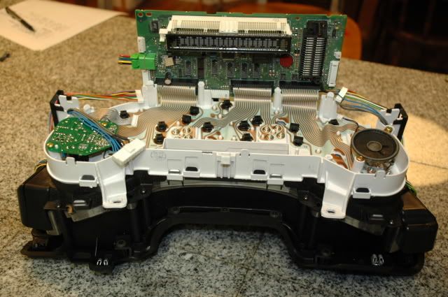
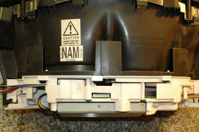
Here is the back side of the gauge cluster:
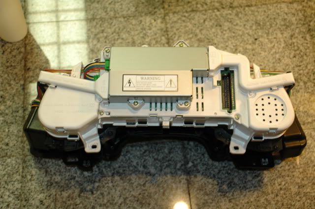
1. Start by removing the two (2) wire harness covers by gently prying back on the plastic tabs.
2. Unplug the 3 wire connectors which are plugged into the power supply (silver box in center).
3. Next unplug the multi-colored wire connectors on each side of the white housing.
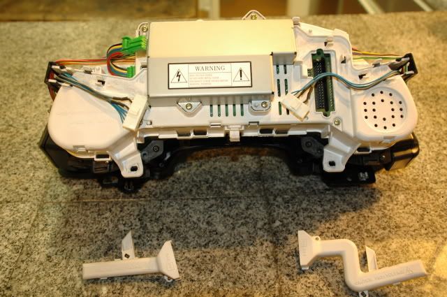
4. Using a Phillips head screw driver, remove the four (4) brass screws which hold the white housing together.
5. Gently bend back the plastic tabs, and separate the cover to expose the circuit board.
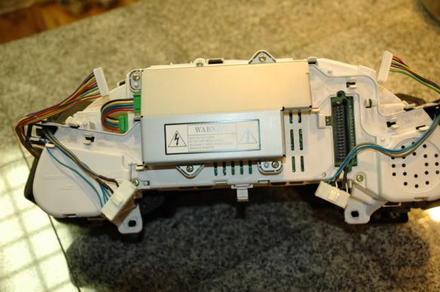
6. Disconnect the speaker connector on the right side and the gray wire harness on the left side.
7. Remove the four (4) T-15 torx screws which secure the circuit board.
8. Gently bend back the three (3) plastic tabs to loosen the circuit board from the housing.
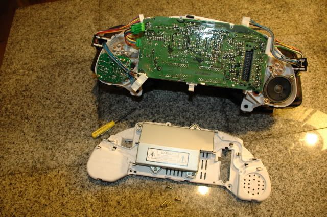
9. Slowly rotate the circuit board toward the top of the cluster to expose the three (3) flat conductor bundles.
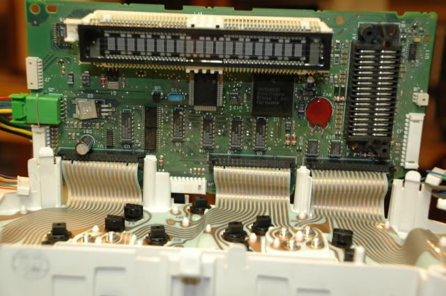
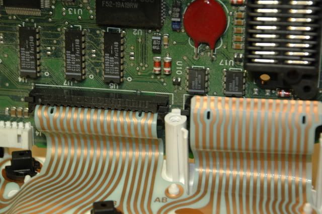
10. Pinch the two black tabs on each connector and wiggle left and right to loosen the connector.
11. Carefully pull the flat conductor bundle out of the connectors.
12. Now lift out the circuit board, and you are ready to install your original (or replacement) DIC circuit board into the gauge cluster.
13. Reverse the procedure to re-assemble the back side of the housing. Be careful to not pinch any wires, and feed the green power supply harness through the housing cover before you snap it back into position.
Bonus material:
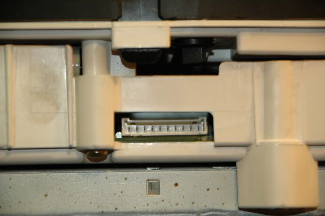
I for one was uncertain if the gauge cluster in my '99 was "HUD ready", as the '97 - early '99 model gauge clusters were not always setup for the HUD. That is one reason I picked up the Z06 cluster along with the HUD projector. So here are a couple of pictures from my '99 cluster to show where the HUD harness connects to the gauge cluster. Apparently my '99 cluster is "HUD ready"
and a close up of the connector:
Here is the back side of the gauge cluster:
1. Start by removing the two (2) wire harness covers by gently prying back on the plastic tabs.
2. Unplug the 3 wire connectors which are plugged into the power supply (silver box in center).
3. Next unplug the multi-colored wire connectors on each side of the white housing.
4. Using a Phillips head screw driver, remove the four (4) brass screws which hold the white housing together.
5. Gently bend back the plastic tabs, and separate the cover to expose the circuit board.
6. Disconnect the speaker connector on the right side and the gray wire harness on the left side.
7. Remove the four (4) T-15 torx screws which secure the circuit board.
8. Gently bend back the three (3) plastic tabs to loosen the circuit board from the housing.
9. Slowly rotate the circuit board toward the top of the cluster to expose the three (3) flat conductor bundles.
10. Pinch the two black tabs on each connector and wiggle left and right to loosen the connector.
11. Carefully pull the flat conductor bundle out of the connectors.
12. Now lift out the circuit board, and you are ready to install your original (or replacement) DIC circuit board into the gauge cluster.
13. Reverse the procedure to re-assemble the back side of the housing. Be careful to not pinch any wires, and feed the green power supply harness through the housing cover before you snap it back into position.
Bonus material:
I for one was uncertain if the gauge cluster in my '99 was "HUD ready", as the '97 - early '99 model gauge clusters were not always setup for the HUD. That is one reason I picked up the Z06 cluster along with the HUD projector. So here are a couple of pictures from my '99 cluster to show where the HUD harness connects to the gauge cluster. Apparently my '99 cluster is "HUD ready"
and a close up of the connector:
Last edited by chevy406; 06-08-2009 at 10:32 PM.

The following 3 users liked this post by chevy406:


The following users liked this post:
My toy vette (04-28-2020)
06-08-2009, 10:46 PM
#4
Tech Contributor
Thread Starter
I have received a lot more from the contributors on this forum than I can possibly give back. The write up on tapping up a wire short in my driver's door harness saved me from hours of frustration and unnecessary troubleshooting.
It is fun to put together a little photo how-to, and hopefully it will encourage another member to tackle the job and save a few bucks.
It is fun to put together a little photo how-to, and hopefully it will encourage another member to tackle the job and save a few bucks.
 06-09-2009, 03:58 AM
#6
Le Mans Master

Member Since: May 2006
Location: DuBois PA
Posts: 5,987
Likes: 0
Received 18 Likes
on
16 Posts
St. Jude Donor '11-'12-'13-'14-'15

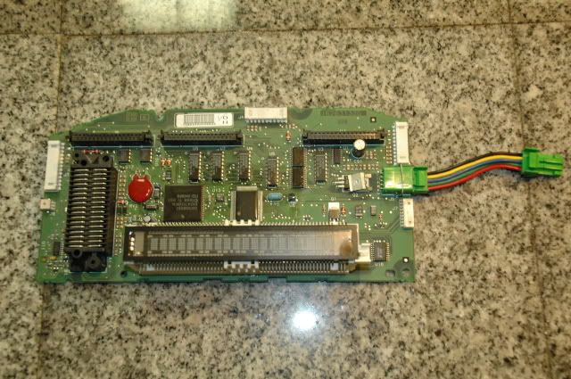
Good grief! OK so the mileage is stored on the main mother board and NOT the little PC board that is to the left of it right???????
Awesome write w/pics!!!! You did a great job documenting this for everyone in the future!
Awesome write w/pics!!!! You did a great job documenting this for everyone in the future!
06-09-2009, 08:12 AM
#7
Tech Contributor
Thread Starter
Originally Posted by tstar
..so the mileage is stored on the main mother board and NOT the little PC board that is to the left of it..
Last edited by chevy406; 06-09-2009 at 08:17 AM. Reason: answered tstar's question
01-06-2010, 02:26 PM
#8
Maybe someone else can help out with your question. In my situation, since I had two complete clusters I simply swapped the two circuit boards and did not have to touch a soldering iron.
I only swapped the DIC circuit board from my '99 cluster to the Z06 cluster, and that worked to keep my odometer with the car. I don't exactly know what the other, smaller circuit board does.
I only swapped the DIC circuit board from my '99 cluster to the Z06 cluster, and that worked to keep my odometer with the car. I don't exactly know what the other, smaller circuit board does.

your "how to " is very interesting and well done but I've got a question regarding the motherboard swapping.
I'd like to change my US cluster by EU cluster with speed indication 0 to 300 And keep the original mileage. Do you know if your modification works in that way too ?
Thanx

Last edited by jmz06; 09-24-2015 at 02:41 PM.
01-21-2010, 03:08 PM
#10
Melting Slicks


The last 2 pics apparently show the HUD connector which would be at the top of the guage cluster - Question:
If you have a guage cluster that does NOT have the HUD connector, what needs to be swapped / done in order to make the GUAGE CLUSTER HUD compatible???? Here's the deal:
I've got a 2001 coupe with HUD already in it. I plan on installing a 300 MPH speedo into my car. BUT, it appears the 300 MPH guage cluster that I have does NOT have the HUD connector on it - so what do I have to do / swap to make the 300 MPH guage cluster work w/ my existing HUD?????
As a side note, I'm planning on putting the english temp and oil guages into the 300 MPH cluster before I install the 300 MPH cluster in my car - so, I already am going to have to take the 300 MPH cluster apart to swap those two guages - BUT what else do I have swap to make the 300 MPH cluster HUD compatible?????
THANKS in advance for any info!!!
01-21-2010, 03:20 PM
#11
Tech Contributor
I have received a lot more from the contributors on this forum than I can possibly give back. The write up on tapping up a wire short in my driver's door harness saved me from hours of frustration and unnecessary troubleshooting.
It is fun to put together a little photo how-to, and hopefully it will encourage another member to tackle the job and save a few bucks.
It is fun to put together a little photo how-to, and hopefully it will encourage another member to tackle the job and save a few bucks.
01-21-2010, 03:47 PM
#12
Le Mans Master
Member Since: Sep 2003
Location: Farmington CT
Posts: 6,126
Received 160 Likes
on
125 Posts
Cruise-In VII Veteran

legal eagle, not sure if you can swap in the HUD board, never tried that, got your pm
01-21-2010, 05:05 PM
#13
Melting Slicks
01-21-2010, 06:25 PM
#14
Tech Contributor


Member Since: Dec 1999
Location: Anthony TX
Posts: 32,736
Received 2,180 Likes
on
1,583 Posts
CI 6,7,8,9,11 Vet
St. Jude Donor '08
Steve is the HUD GOD.. He has all kinds of C5 HUD knowledge. Parts too!
Your in good hands!
BC
Your in good hands!
BC
01-22-2010, 12:43 AM
#15
Melting Slicks
Steve, Bill C or anyone in the know:
As above, I've got a 2001 Coupe w/ factory HUD and I want to put in a 300 MPH speedo - I know other's have done this and that it can be done; the 300 MPH speedo comes w/ the temp and oil pressure reading in Metric (that's not right terminology, but you get the drift) - I know that US temp and oil pressure guages can be swapped INTO a 300 MPH speedo prior to installing the 300 MPH speedo in the car - this obviously results in all English guages, but a 300 MPH speedo - and this is my goal - SO . . .
is there any reason that anyone can think of that I can't use a English cluster (ie: Steve's cluster) that is factory HUD and swap the 300 MPH speedo INTO the English cluster? seems that if you can swap English temp and oil pressure guages INTO a 300 MPH cluster and get that to work, that you SHOULD be able to swap a 300 MPH speedo guage into an English cluster and that should work - CORRECT???
05-08-2011, 01:05 PM
#16
My 1998 vette, has no hud enabled wiring on the dic circuit board.. So when you swap them you still gain nothing... You still need a qualified shop to do it... The only one I know is h and r radio in horsham, pa......
12-25-2014, 01:45 AM
#17
Intermediate


Member Since: Dec 2008
Location: Clarksville Tennessee
Posts: 37
Likes: 0
Received 0 Likes
on
0 Posts
Do I have to replace my entire gage cluster now?
10-18-2015, 03:16 AM
#18

I recently picked up a used Heads Up Display (HUD) and a Z06 gauge cluster from a forum member through the C5 parts classifieds. While the HUD installation is well documented on this forum (thanks for all the great write ups and pictures), there is still a lot of uncertainty and question about how to handle the odometer if one were to swap out a guage cluster from another C5. With the help of my trusty Nikon D70, I would like to show how easily the Drivers Information Center (DIC) circuit board can be removed from one gauge cluster and installed in another.
Here is the back side of the gauge cluster:
1. Start by removing the two (2) wire harness covers by gently prying back on the plastic tabs.
2. Unplug the 3 wire connectors which are plugged into the power supply (silver box in center).
3. Next unplug the multi-colored wire connectors on each side of the white housing.
4. Using a Phillips head screw driver, remove the four (4) brass screws which hold the white housing together.
5. Gently bend back the plastic tabs, and separate the cover to expose the circuit board.
6. Disconnect the speaker connector on the right side and the gray wire harness on the left side.
7. Remove the four (4) T-15 torx screws which secure the circuit board.
8. Gently bend back the three (3) plastic tabs to loosen the circuit board from the housing.
9. Slowly rotate the circuit board toward the top of the cluster to expose the three (3) flat conductor bundles.
10. Pinch the two black tabs on each connector and wiggle left and right to loosen the connector.
11. Carefully pull the flat conductor bundle out of the connectors.
12. Now lift out the circuit board, and you are ready to install your original (or replacement) DIC circuit board into the gauge cluster.
13. Reverse the procedure to re-assemble the back side of the housing. Be careful to not pinch any wires, and feed the green power supply harness through the housing cover before you snap it back into position.
Bonus material:
I for one was uncertain if the gauge cluster in my '99 was "HUD ready", as the '97 - early '99 model gauge clusters were not always setup for the HUD. That is one reason I picked up the Z06 cluster along with the HUD projector. So here are a couple of pictures from my '99 cluster to show where the HUD harness connects to the gauge cluster. Apparently my '99 cluster is "HUD ready"
and a close up of the connector:
Since I can't start a thread yet, I thought I'd post on the most related thread on CF regarding DIC problems and having seen someone willing to give a donor IPC to someone and ask members for an item I need (which is a working IPC with at least a lit DIC display - not working properly DIC is okay as long as it lights up and shows some digital info), and I REALLY need the connector and short poece of its harness attached so I can power up the IPC on my test bench. What I want to be able to do is determine if there is a way to simply add an on / off switch to turn of the DIC display and turn it on when desired. My DIC on my newly acquired C5 is intermittently turning on without any buttons being pressed (the DIC buttons are perfectly fine and do what they're supposed to do when needed), but instead of taking a chance buying a used IPC, hope it works, then sending it out and paying to reset the mileage, if your DIC mostly works but comes on at times and scrolls etc while driving, the ability to just turn that off independent of all other functions is the goal for me. To do that I need at a minimum, a connector and its harness attached. As mentioned a donor IPC for the purpose of checking the DIC power and other functions would be great. This could help a lot of C5 owners. What say you guys?
10-18-2015, 03:39 PM
#19
Melting Slicks

Thank you OP for this write up. Great job!

