UPDATED Again 8/25/13**** Ultimate DIY/FAQ Thread ...It's All in HERE!!


 11-10-2007, 03:51 PM
#24
Melting Slicks

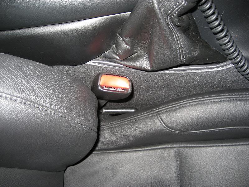
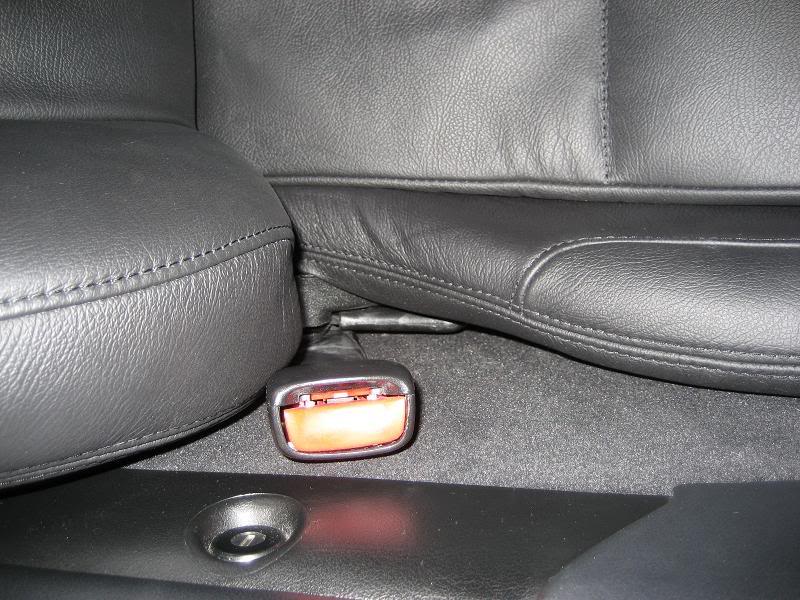
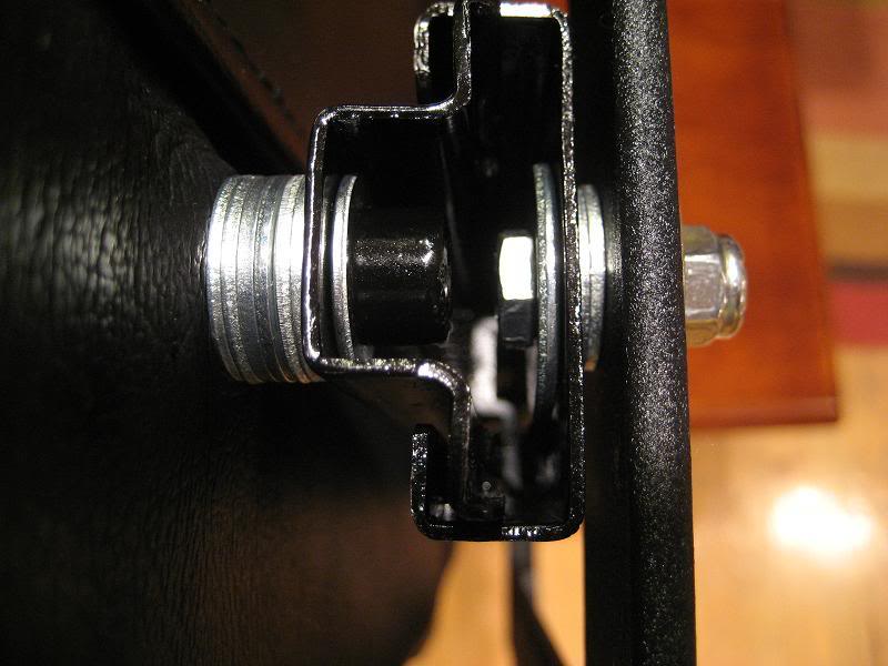
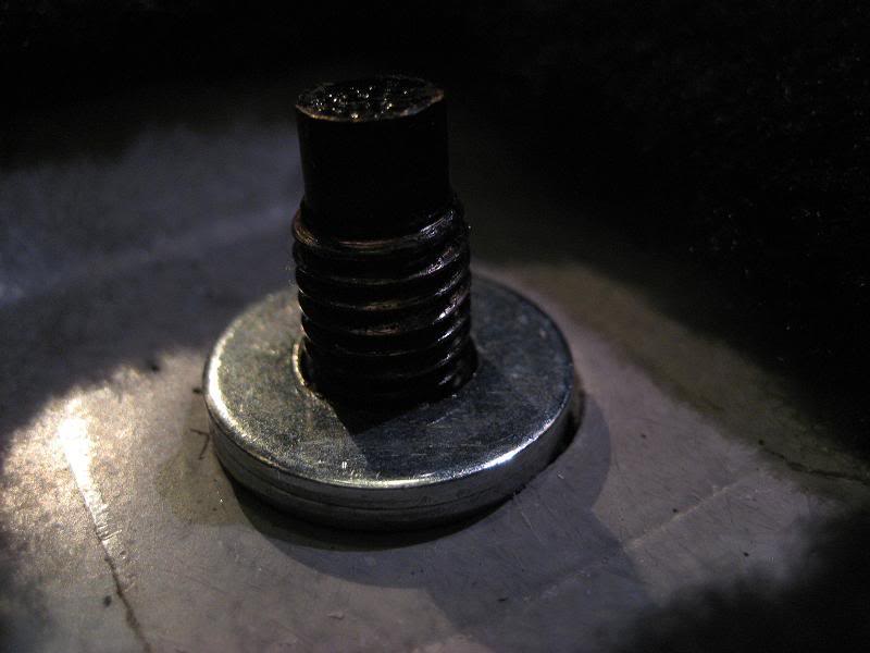
Post #23 above has some good instructions on how to install an auto dimming mirror in a car that didn't come with one. This is a good thread to add to that with some pictures I took of my install. If anyone has any questions, feel free to PM me.
http://forums.corvetteforum.com/show...post1562691970
http://forums.corvetteforum.com/show...post1562691970
 11-25-2007, 08:17 AM
#25
Intermediate

Member Since: Apr 2004
Location: Kennesaw GA
Posts: 33
Likes: 0
Received 0 Likes
on
0 Posts
 12-24-2007, 09:30 PM
#28
Racer
Member Since: Jul 2006
Location: San Jose Ca
Posts: 447
Likes: 0
Received 0 Likes
on
0 Posts
I don't want to take credit for this, I took it from someone elses site, a very good write-up on getting the intake manifold off for either the check valve or oil pressure sending unit.
http://pages.infinit.net/vette747/IntakeManifold
Great to have a DIY thread.
Other DIY on this site
http://pages.videotron.com/vette747/
http://pages.infinit.net/vette747/IntakeManifold
Great to have a DIY thread.
Other DIY on this site
http://pages.videotron.com/vette747/
12-31-2007, 02:16 AM
#29
Tech Contributor
Member Since: Dec 2003
Location: Horncastle Lincolnshire, England
Posts: 19,384
Likes: 0
Received 79 Likes
on
61 Posts
2023 C5 of the Year Finalist - Unmodified

Refurbishing a Corvette C5 Hood Liner
The liner is made of a very delicate material so be careful in how you handle it once it’s removed. The surface is a fabric type finish and hard brushing will cause it to become rough and fibrous. It will also crack easily if you let it flex so if you take it outside beware of strong wind.
As you take the final fasteners out, support the liner so you don’t crack the liner around the eyelets.
The actual work takes only minutes. The drying time is the only slow process.
As you can see, the liner will have attracted quite a bit of dirt and grime.
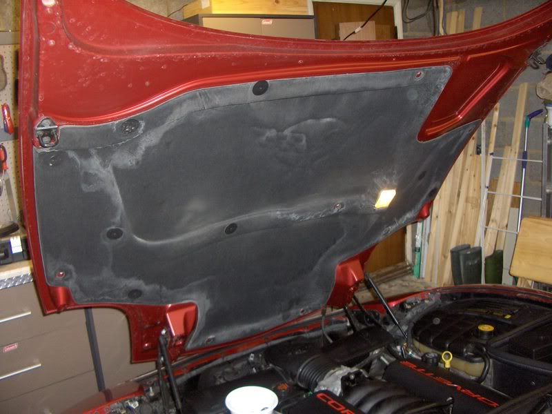
OK here we go.
Lift the hood.
Remove the fasteners gently, top, then bottom and middle ones last. This will support the liner better as you take them out. Us a tool with a forked end. I’ve heard of a barbeque fork being used. I used a nail puller work in behind the fastener.
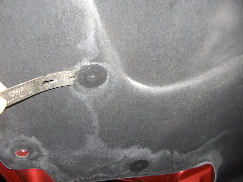
Take the liner outside and brush the surface gently with a soft brush to remove any dirt. Take care not to damage the surface of the liner.
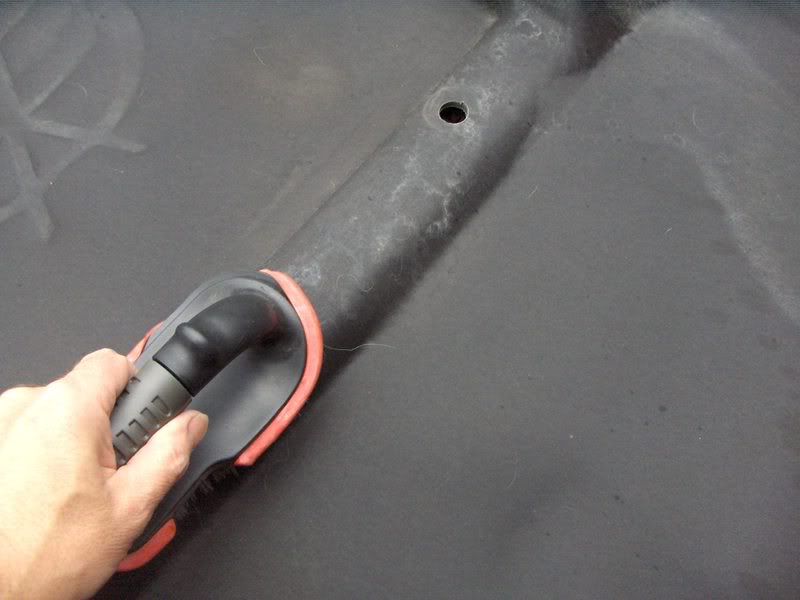
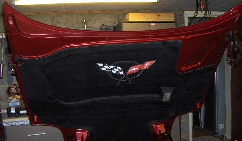
Spray the liner with black paint. The difference between the old and the new surface is immediately apparent.
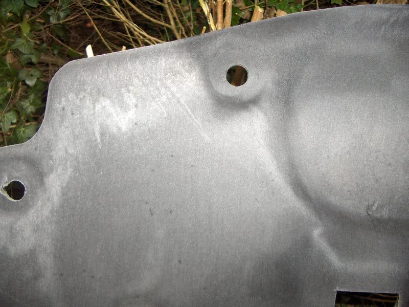
Use as many coats as you see fit. The liner is porous so it will take at least 3 coats to get good coverage. Leave it for 30 mins between coats to allow the paint to dry.
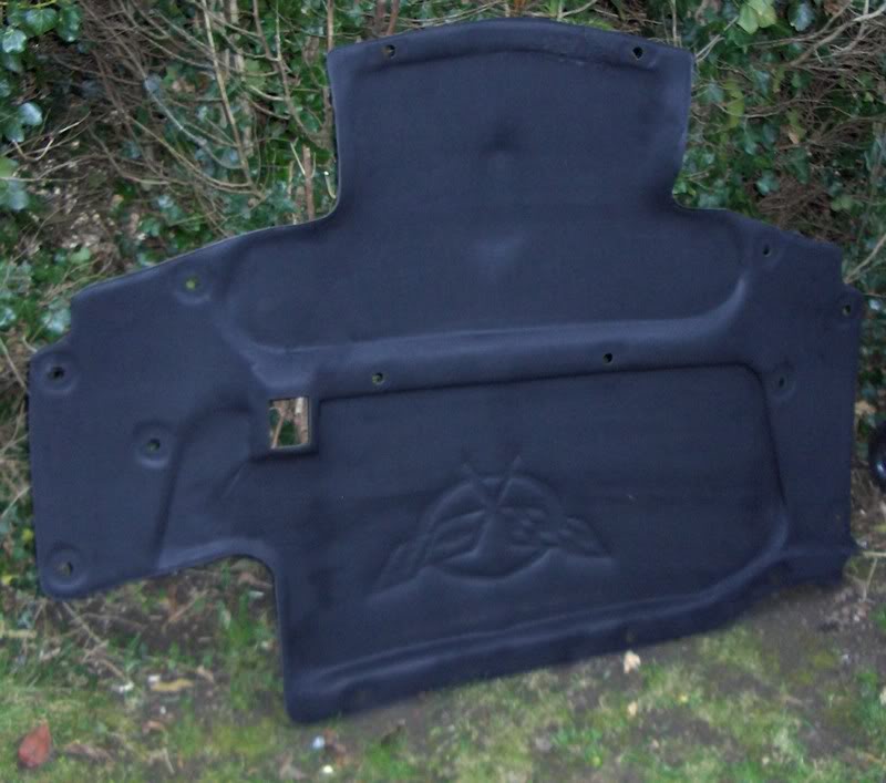
If you plan to paint the Corvette emblem, you may wish to apply extra paint around the embossed area on the liner. This will stop the liner absorbing the coloured paint.
Once the paint is dry (and you may wish to leave it overnight), you can either paint the emblem or apply a decal. I chose the decal. Alternatively if you prefer, you can refit the liner and apply the decal when it’s back in place.
Refit the liner in the hood fitting the middle fasteners first to hold it in place, then refit the remaining fasteners. A gentle push fit is all it takes to reinsert the fastener.
The finished Hood Liner
The liner is made of a very delicate material so be careful in how you handle it once it’s removed. The surface is a fabric type finish and hard brushing will cause it to become rough and fibrous. It will also crack easily if you let it flex so if you take it outside beware of strong wind.
As you take the final fasteners out, support the liner so you don’t crack the liner around the eyelets.
The actual work takes only minutes. The drying time is the only slow process.
As you can see, the liner will have attracted quite a bit of dirt and grime.
OK here we go.
Lift the hood.
Remove the fasteners gently, top, then bottom and middle ones last. This will support the liner better as you take them out. Us a tool with a forked end. I’ve heard of a barbeque fork being used. I used a nail puller work in behind the fastener.
Take the liner outside and brush the surface gently with a soft brush to remove any dirt. Take care not to damage the surface of the liner.
Spray the liner with black paint. The difference between the old and the new surface is immediately apparent.
Use as many coats as you see fit. The liner is porous so it will take at least 3 coats to get good coverage. Leave it for 30 mins between coats to allow the paint to dry.
If you plan to paint the Corvette emblem, you may wish to apply extra paint around the embossed area on the liner. This will stop the liner absorbing the coloured paint.
Once the paint is dry (and you may wish to leave it overnight), you can either paint the emblem or apply a decal. I chose the decal. Alternatively if you prefer, you can refit the liner and apply the decal when it’s back in place.
Refit the liner in the hood fitting the middle fasteners first to hold it in place, then refit the remaining fasteners. A gentle push fit is all it takes to reinsert the fastener.
The finished Hood Liner
Last edited by DeeGee; 02-16-2008 at 02:18 AM.


 02-07-2008, 07:18 PM
#31
Melting Slicks
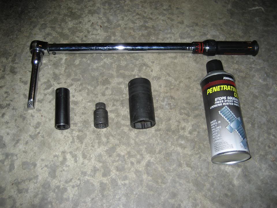
Here are all of the tools that you will need: 33mm deep well 6-point socket (I purchased replacement spindle buts that had 34mm heads, so double check this before sitting down to do the job), 19mm socket, torque wrench, wheel lock key, some penetrating fluid (I prefer "PB Blaster" but didn't have any handy when I did this) and some synthetic grease (not pictured).
Pull off the center cap for your wheels and break loose the lug nuts and output shaft spindle nut. The spindle nut could be pretty tight so don't be surprised if it takes a bit of elbow grease to get it to break loose.
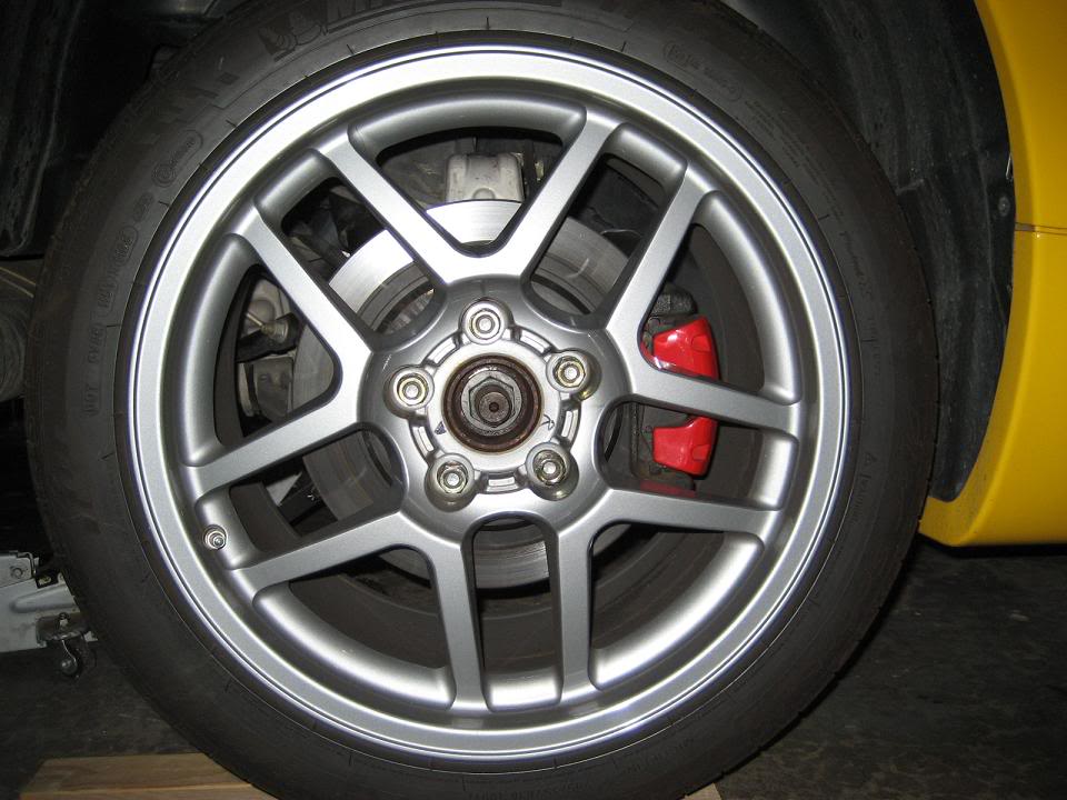
Jack up the rear end, support the car, spin the lug nuts off, and remove the rear wheels, you will now be looking at this.
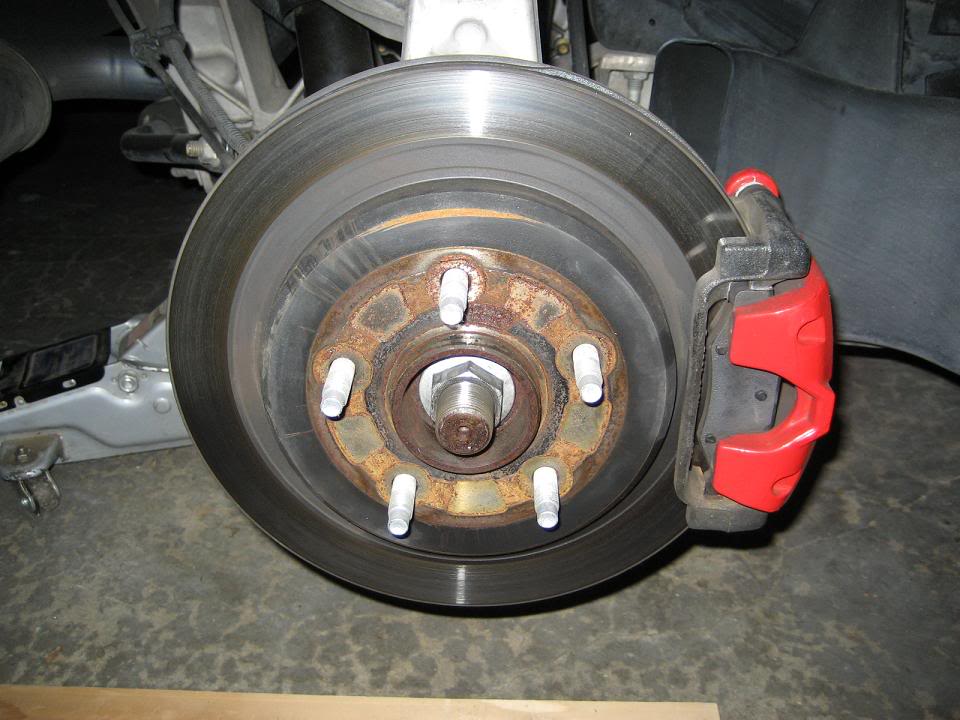
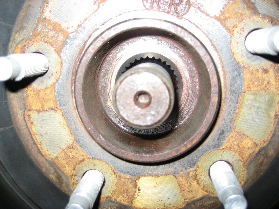
Now you don't have to worry about hitting your wheel with the torque wrench or busting your knuckes open on the wheel. Remove the spindle nut the rest of the way and take a good look at what is behind it.
Now we can see the front side of the splines that mate the output shaft and the hub assembly. Go ahead and give a little squirt of the penetrating fluid into these ridges, but not too much cause this isn't the important part. If you push in (towards the transmission) on the middle of the output shaft it should slide in to the hub. If it's rusted in place a light tap with brass hammer or mallet should break it loose so you can now move it by hand.
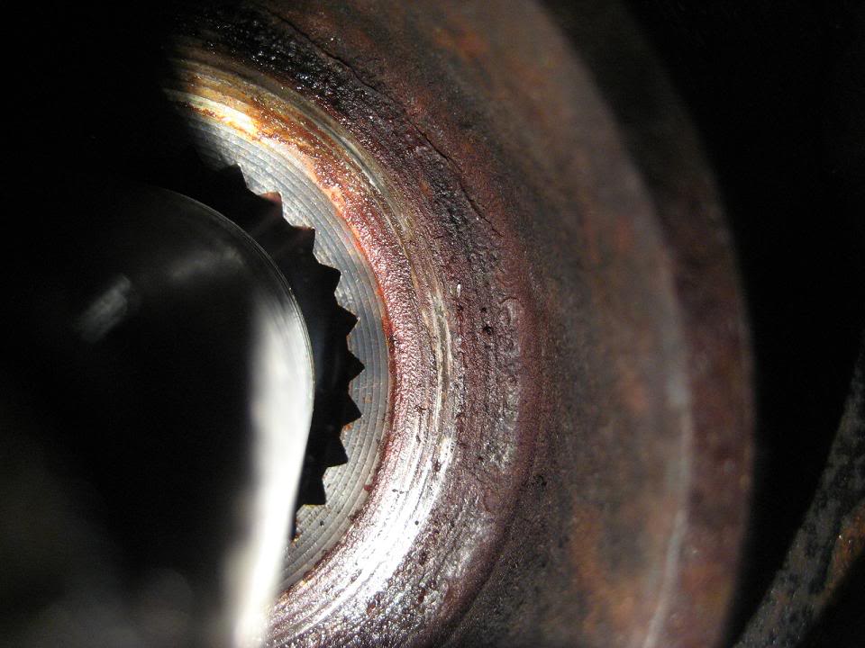
Now while pushing in look behind the hub assembly and look at where the drive shaft actually goes into the hub. If you look carefully you can see the splines entering the hub, and the mating surface of where the drive shaft buts against the hub. Give this area a nice layer of synthetic grease, both on the splines and the flat portion where output shaft meets hub (I used penetrating fluid the first couple times around but the problem kept coming back, once I used grease it stayed gone).
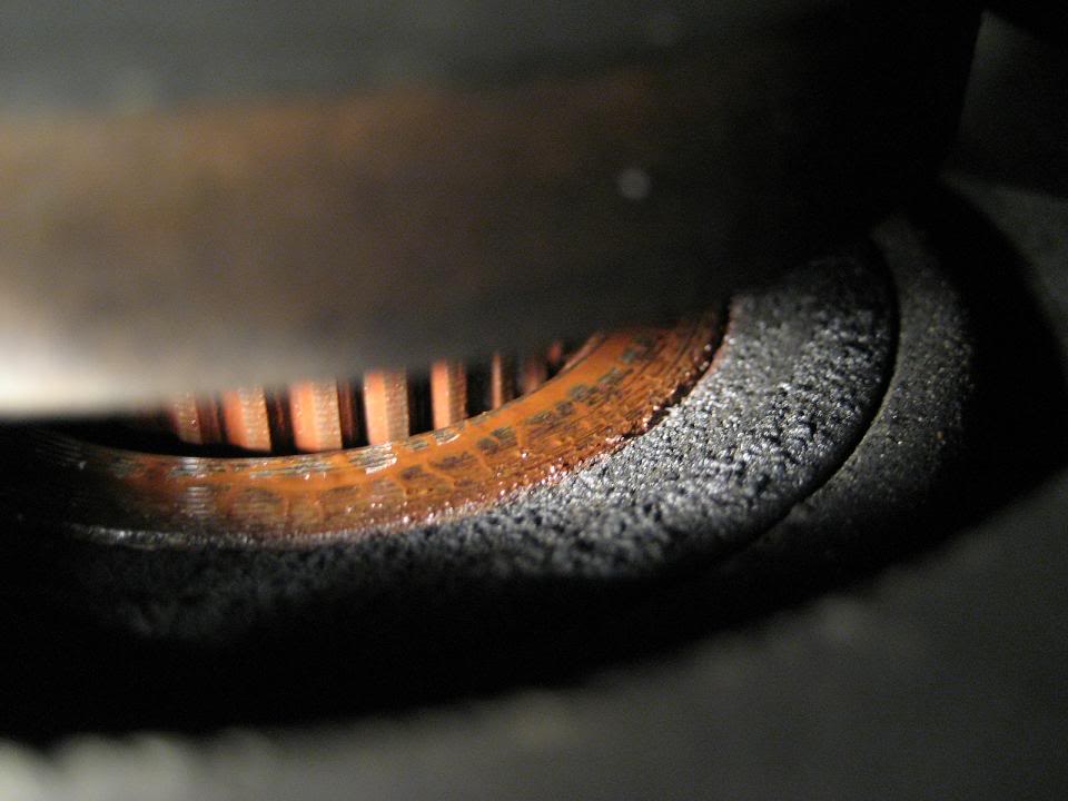
Work the spindle back and fourth in the hub a few times to make sure that the penetrating fluid has completely covered the splines and all contact areas have at least a thin layer of grease on them.
Spin the spindle nut back on until snug, put your wheel back on and snug the lug nuts down. Drop back to the ground and torque the spindle nut to 118 ft/lbs and the lug nuts to 100 ft/lbs (make sure to torque in a star pattern so you get even torque).
Now go for a test drive and listen to the beautiful silence coming from the rear end. After driving a few miles I like to double check torque on the spindle nut, but I don't know how necessary that really is.
Hope this helps!!!
Pull off the center cap for your wheels and break loose the lug nuts and output shaft spindle nut. The spindle nut could be pretty tight so don't be surprised if it takes a bit of elbow grease to get it to break loose.
Jack up the rear end, support the car, spin the lug nuts off, and remove the rear wheels, you will now be looking at this.
Now you don't have to worry about hitting your wheel with the torque wrench or busting your knuckes open on the wheel. Remove the spindle nut the rest of the way and take a good look at what is behind it.
Now we can see the front side of the splines that mate the output shaft and the hub assembly. Go ahead and give a little squirt of the penetrating fluid into these ridges, but not too much cause this isn't the important part. If you push in (towards the transmission) on the middle of the output shaft it should slide in to the hub. If it's rusted in place a light tap with brass hammer or mallet should break it loose so you can now move it by hand.
Now while pushing in look behind the hub assembly and look at where the drive shaft actually goes into the hub. If you look carefully you can see the splines entering the hub, and the mating surface of where the drive shaft buts against the hub. Give this area a nice layer of synthetic grease, both on the splines and the flat portion where output shaft meets hub (I used penetrating fluid the first couple times around but the problem kept coming back, once I used grease it stayed gone).
Work the spindle back and fourth in the hub a few times to make sure that the penetrating fluid has completely covered the splines and all contact areas have at least a thin layer of grease on them.
Spin the spindle nut back on until snug, put your wheel back on and snug the lug nuts down. Drop back to the ground and torque the spindle nut to 118 ft/lbs and the lug nuts to 100 ft/lbs (make sure to torque in a star pattern so you get even torque).
Now go for a test drive and listen to the beautiful silence coming from the rear end. After driving a few miles I like to double check torque on the spindle nut, but I don't know how necessary that really is.
Hope this helps!!!
02-07-2008, 07:27 PM
#32
Melting Slicks
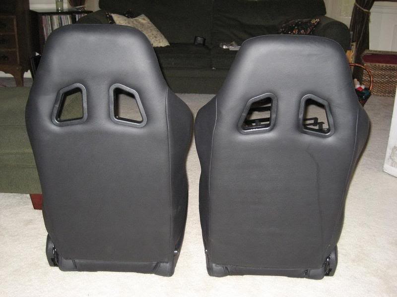
Everything arrived in a single monstrous box, and as I unpacked the inventory began. First thing I grabbed was an allen head taped to the bottom of one of the seats - it was the wrong size and didn't fit a single thing in the assembly (a sign of things to come)...
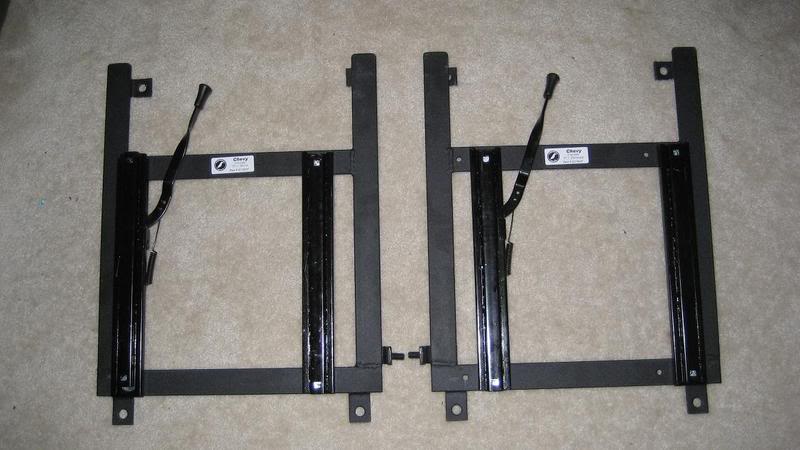
Two C5 mounting brackets:
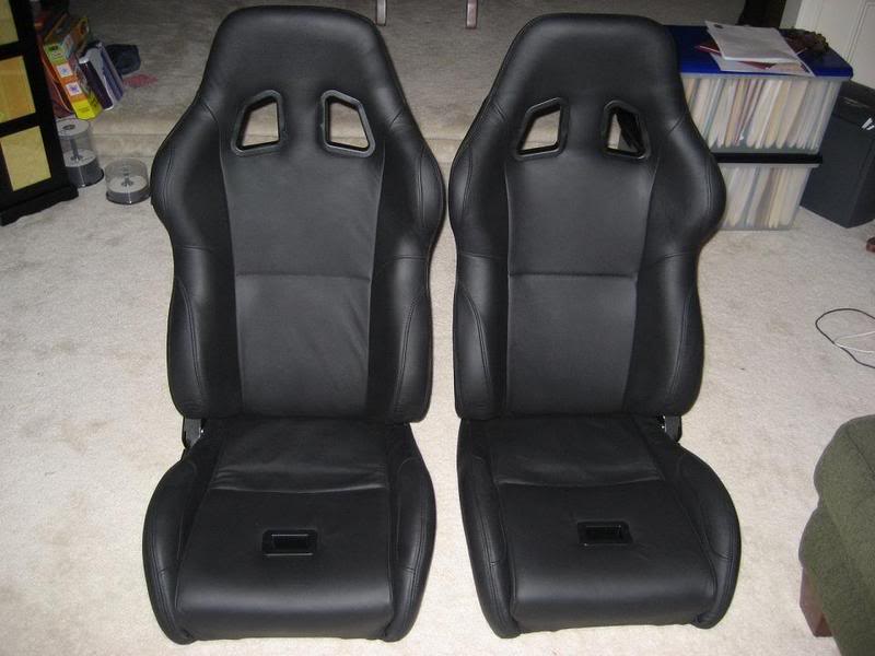
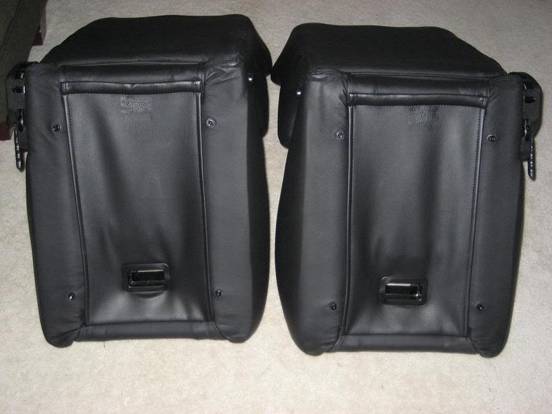
Tow Corbeau A4 Leather seats with sub-belt slot installed:
First things first I needed to mount the seats on their respective brackets. After talking with Corbeau I decided to mount the passenger side seat on the drivers side bracket and visa versa. Otherwise people have reported the reclining handle interferes with the seatbelt reel.
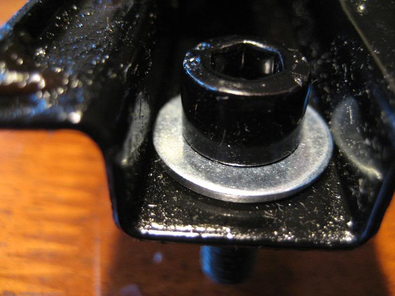
The first thing I noticed when beginning to mount the brackets was there were square holes on the brackets, that were quite larger than the actual bolt head that held the seat secure. I am pretty sure it would have worked ok, but decided to add a washer to the assembly and ensure a solid and uniform contact surface for the bolts.
I grabbed a bracket and made my first trip to the hardware store and picked up eight 1/4" steel flat washers. This size fit the mounting bolt perfectly, provided a larger/flatter mounting surface for the bolt, and also fit perfectly in the rails so there was no possible slop from side to side.
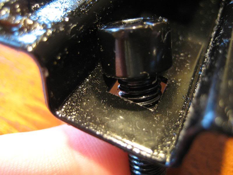
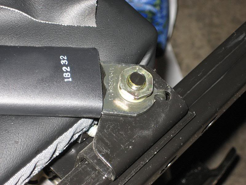
Here is what the bracket and seat mounting bolt looked like if assembled with out any additional hardware:
Here is what it looked like with the washer added:
Now that I had the appropriate hardware it was time to secure the seats to their brackets. I decided to use a dab of blue lock-tight and ease any worries of the bolts backing themselves out. You can't access all 4 mounting holes at the same time, so slide the adjuster all the way to one side and install two bolts - then slide it back to the other side and install the other two. Also note that since the supplied allan head was the wrong size I used a 6mm allan head socket to tighten the bolts down.
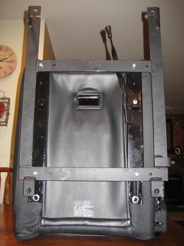
Seat and bracket mounted together:
Now I headed out to my car to begin the removal of the passenger side seat. I decided since the car is a daily driver I would replace the passenger side first and solve any installation issues prior to removing driver seat.
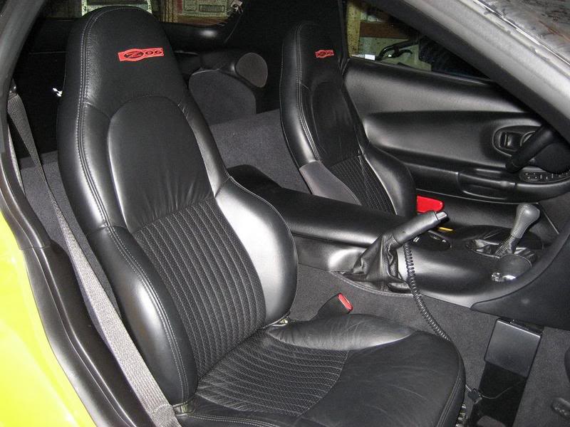
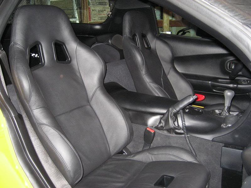
A pic of the stock Z06 seats installed:
continued in next post...
Two C5 mounting brackets:
Tow Corbeau A4 Leather seats with sub-belt slot installed:
First things first I needed to mount the seats on their respective brackets. After talking with Corbeau I decided to mount the passenger side seat on the drivers side bracket and visa versa. Otherwise people have reported the reclining handle interferes with the seatbelt reel.
The first thing I noticed when beginning to mount the brackets was there were square holes on the brackets, that were quite larger than the actual bolt head that held the seat secure. I am pretty sure it would have worked ok, but decided to add a washer to the assembly and ensure a solid and uniform contact surface for the bolts.
I grabbed a bracket and made my first trip to the hardware store and picked up eight 1/4" steel flat washers. This size fit the mounting bolt perfectly, provided a larger/flatter mounting surface for the bolt, and also fit perfectly in the rails so there was no possible slop from side to side.
Here is what the bracket and seat mounting bolt looked like if assembled with out any additional hardware:
Here is what it looked like with the washer added:
Now that I had the appropriate hardware it was time to secure the seats to their brackets. I decided to use a dab of blue lock-tight and ease any worries of the bolts backing themselves out. You can't access all 4 mounting holes at the same time, so slide the adjuster all the way to one side and install two bolts - then slide it back to the other side and install the other two. Also note that since the supplied allan head was the wrong size I used a 6mm allan head socket to tighten the bolts down.
Seat and bracket mounted together:
Now I headed out to my car to begin the removal of the passenger side seat. I decided since the car is a daily driver I would replace the passenger side first and solve any installation issues prior to removing driver seat.
A pic of the stock Z06 seats installed:
continued in next post...
02-07-2008, 07:29 PM
#33
Melting Slicks
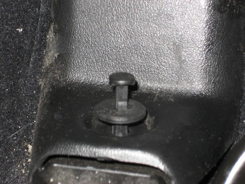
First thing to remove are the plastic covers on the front ends of the factory mounting rails. I like to use a pair of small wire clippers to ease the center of the pins out, I have broken too many by prying them out with a pocket screwdriver.
Plastic covers and center pins pulled partially out:
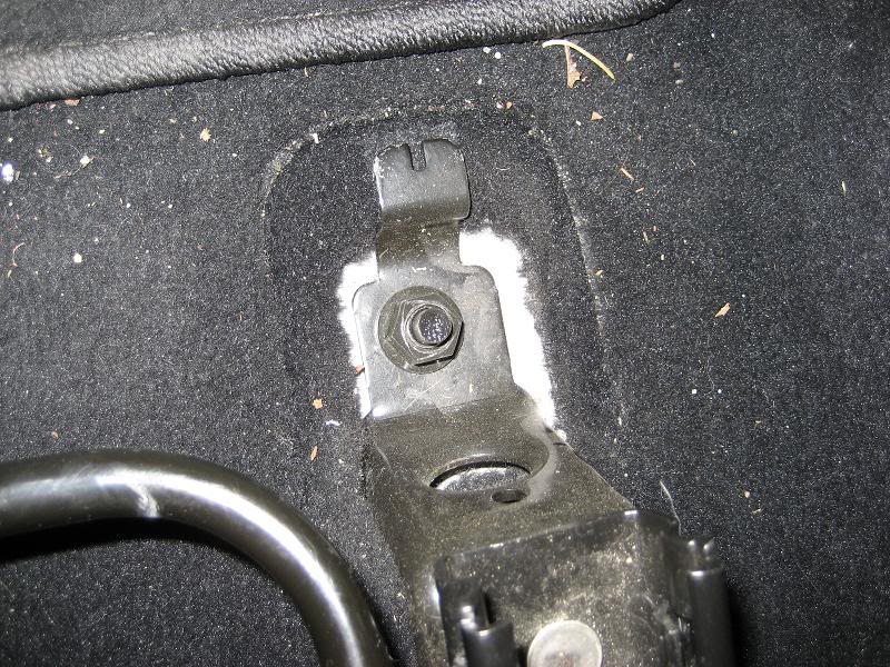
After the pins are pulled the plastic covers slide off toward the front of the car and expose the mounting bolts underneath. It takes a 15mm socket to remove the bolts, there is one at each corner of the mounting bracket.
One of the mounting bolts:
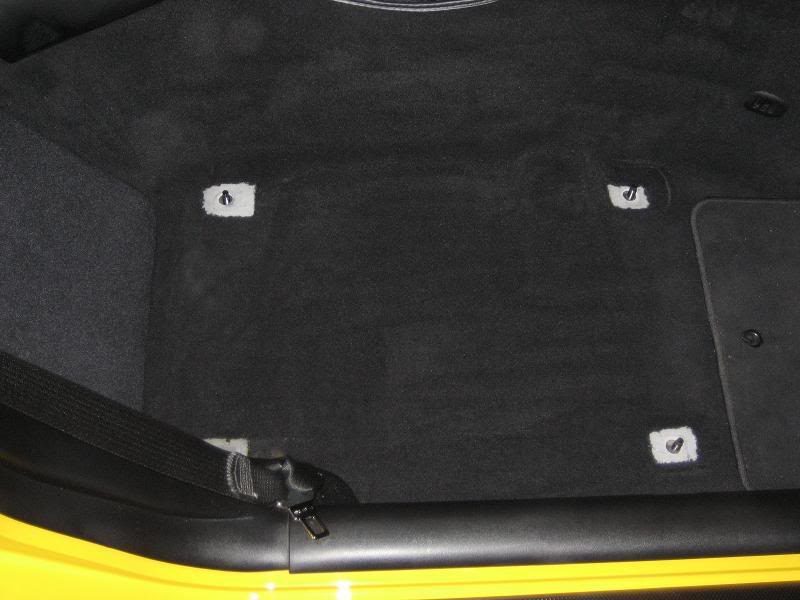
Remove all four of the nuts and the seat will lift out - it might take a little maneuvering but nothing too difficult. Take a look and see what kind of goodies have been floating around under the seats, I found my pocket screwdriver that had been missing for a month. This is also a perfect time to vacuum!
Seat removed and vacumed underneath, the 4 mounting bolts are exposed:
Next thing to do is swap the seat belt receptacle onto the new brackets. You will need an 18mm socket for this portion and some elbow grease because there was some factory lock-tight on this bolt. Make sure you keep everything that comes off, especially the plastic grommet.
Stock bracket with receptacle:
Now take this to the Corbeau bracket and install in the same fashion. The Corbeau bracket didn't have a hole drilled for the retainer pin, and I didn't feel like taking the time to drill one myself. I decided the pin could sit off to the side of the bracket, as it would still provide full swing in the usable direction for the seat belt.
With the seats swapped the belt receptacle will now be on the same side as the recline lever - but this is a better alternative than having the lever interfere with the seat belt reel.
Receptacle installed on Corbeau bracket:
Now you are ready to bolt the seat into the car. Placing the seat assembly in the car is the easy part - getting the bracket low enough to tighten down the nuts is another. Even with the seats swapped there is still quite a bit of interference between the seat hinge and the seat belt reel. I had to lean heavily on the seat and try to get the threads started at the same time for the back nuts.
The main interference point:
Get the rears started, but not all the way tight and then go to the front two and do the same. Once all 4 are started go ahead and tighten them all down. As far as I can tell there is no way to modify the factory rail covers to fit the Corbeau rails, so they stay eternally exposed along the floorboard.
One of the front bolts tightened down on the Corbeau bracket:
continued in next post...
Plastic covers and center pins pulled partially out:
After the pins are pulled the plastic covers slide off toward the front of the car and expose the mounting bolts underneath. It takes a 15mm socket to remove the bolts, there is one at each corner of the mounting bracket.
One of the mounting bolts:
Remove all four of the nuts and the seat will lift out - it might take a little maneuvering but nothing too difficult. Take a look and see what kind of goodies have been floating around under the seats, I found my pocket screwdriver that had been missing for a month. This is also a perfect time to vacuum!
Seat removed and vacumed underneath, the 4 mounting bolts are exposed:
Next thing to do is swap the seat belt receptacle onto the new brackets. You will need an 18mm socket for this portion and some elbow grease because there was some factory lock-tight on this bolt. Make sure you keep everything that comes off, especially the plastic grommet.
Stock bracket with receptacle:
Now take this to the Corbeau bracket and install in the same fashion. The Corbeau bracket didn't have a hole drilled for the retainer pin, and I didn't feel like taking the time to drill one myself. I decided the pin could sit off to the side of the bracket, as it would still provide full swing in the usable direction for the seat belt.
With the seats swapped the belt receptacle will now be on the same side as the recline lever - but this is a better alternative than having the lever interfere with the seat belt reel.
Receptacle installed on Corbeau bracket:
Now you are ready to bolt the seat into the car. Placing the seat assembly in the car is the easy part - getting the bracket low enough to tighten down the nuts is another. Even with the seats swapped there is still quite a bit of interference between the seat hinge and the seat belt reel. I had to lean heavily on the seat and try to get the threads started at the same time for the back nuts.
The main interference point:
Get the rears started, but not all the way tight and then go to the front two and do the same. Once all 4 are started go ahead and tighten them all down. As far as I can tell there is no way to modify the factory rail covers to fit the Corbeau rails, so they stay eternally exposed along the floorboard.
One of the front bolts tightened down on the Corbeau bracket:
continued in next post...
02-07-2008, 07:30 PM
#34
Melting Slicks
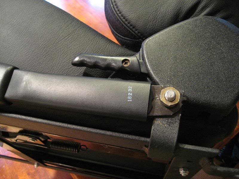
The drivers side installs in the same fashion as the passenger side. The only difference is you have to unclip the wiring for the power seats and leave it dangling loose under the seat. I am not getting any seatbelt lights or strange codes from not having that plugged in, but I could just be lucky cause I have heard of others having issues.
Both sides have their reclining ***** buried down next to the transmission tunnel. They are far from easy to get to, but it can be done - and adjusting the amount of recline really isn't that common for me anyway...
Passenger side:
Drivers side:
Here is the finished product with both sides installed and ready for action:
Cumulative tools needed:
ratchet
18mm socket
15mm socket
pocket screwdriver
small wire cutters or needle nose pliers
6mm allen head socket
(8) 1/4" flat washers
lock-tight
After living with the seats for a couple weeks I wanted to change four things:
1 - How far forward I could move the seat
2 - Angle of the seat backrest (my back pain was coming from a twisted feeling in the seat)
3 - Angle of the bottom seat cushion and support (forward to back)
4 - Seat belts ride far too high
Issue 1&2 - After removing the drivers seat and taking a look at how it is mounted to the rails and bracket (picture in 1st post) it was obvious there isn't any way to significantly move the bracket or rail mounting position forward. The bracket mounting bars went side-to-side instead of front-to-back, and the rail mounting holes were already at the very end - thus tapping new holes wasn't an option. The only way that I was going to significantly move the seat further forward was to weld additional material onto the existing bracket - and I don't have a shop in house any more so that was out of the question.
The one thing that saved me here was the multiple locations of attachment between seat, slide rails, mounting bracket, and floorboard. I noticed that if I added pressure to the entire assembly with all fasteners loose I could gain an extra 1/2" or so of movement toward the front. Additionally I could twist the entire assembly 5-10 degrees left or right with everything loose. With a little help we added as much forward and clockwise pressure as possible to the seat while I tightened down all the fasteners. Also while bolting the seat back down to the floorboard I made sure there was as much forward and clockwise pressure as possible.
Issue 3 - This one I had taken a half-a$$ attempt at fixing the night prior but ran out of time and didn't have much luck. Now it was time to do things right!
There were four places that I could improve the end angle of the seat, and give it a bit of rake toward the back.
1st spot - When delivered from Corbeau there was a washer between the mounting bracket and seat rail on all four corners. First thing I did was remove the washer on the back two slots and place it on the outside (sorry, no pic for this one).
2nd spot - When originally mounted there were no washers or spacers between the seat and slide rails. I decided as a first attempt to add six 1/4" flat washers between the seat for the two front mounting bolts. The mounting hardware is suprisingly long here and I didn't have any worries about having sufficient threads available to get a good bite on the seat - even with the additional 6 washers.
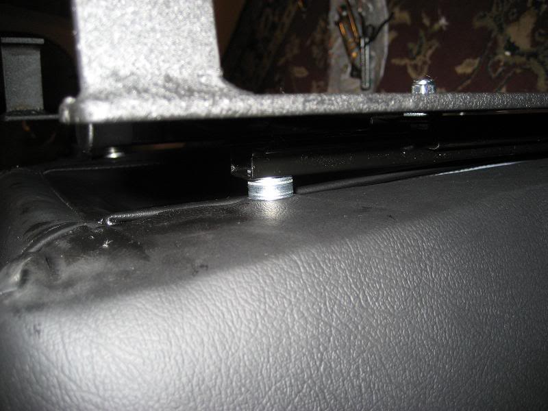
3rd spot - While not much room for improvement using the original hardware there was room for 2 additional 1/4" washers between the mounting bracket and slide rails. The pic below shows both the 6 stacked between seat/rails and the two stacked between rails/bracket.
4th spot - I added two 5/8" washers between the floorboard and mounting brackets. This was the easiest place to make a difference, but because of how short the mounting studs are I could only add two washers.
Issue 4 - nothing I can do about this for now. I am currently looking for a pair of the receiver ends so I can cut them down, re-tap and re-install 2-3 inches lower.
Result - Overall the seat feels 10 times better. Tilting the seat bottom back made all the difference in the world. Now instead of falling forward out of the seat I am tucked tightly down into the bolsters and can firmly feel the entire seat. With the seat all the way forward and back raised I can now confidently and firmly grasp the wheel, gear shift and the pedals are the perfect distance away. The pain in my lower back is gone after getting rid of the ackward twist from the initial install, and I feel overall better planted to the back of the seat.
Now all I have to do is make the same changes to the passenger side and I am going to call it good for now. I am thinking about creating some full length wood shims to go between the seat and sliders to keep the seat frame from sagging, but that will be down the road some time.
EDIT - I got additional hardware and ended up with 5 washers between the bracket and rails, 8 washers between the rails and seat, and left 2 between the bracket and floorboard. I think this is as close as I am going to get...
Both sides have their reclining ***** buried down next to the transmission tunnel. They are far from easy to get to, but it can be done - and adjusting the amount of recline really isn't that common for me anyway...
Passenger side:
Drivers side:
Here is the finished product with both sides installed and ready for action:
Cumulative tools needed:
ratchet
18mm socket
15mm socket
pocket screwdriver
small wire cutters or needle nose pliers
6mm allen head socket
(8) 1/4" flat washers
lock-tight
After living with the seats for a couple weeks I wanted to change four things:
1 - How far forward I could move the seat
2 - Angle of the seat backrest (my back pain was coming from a twisted feeling in the seat)
3 - Angle of the bottom seat cushion and support (forward to back)
4 - Seat belts ride far too high
Issue 1&2 - After removing the drivers seat and taking a look at how it is mounted to the rails and bracket (picture in 1st post) it was obvious there isn't any way to significantly move the bracket or rail mounting position forward. The bracket mounting bars went side-to-side instead of front-to-back, and the rail mounting holes were already at the very end - thus tapping new holes wasn't an option. The only way that I was going to significantly move the seat further forward was to weld additional material onto the existing bracket - and I don't have a shop in house any more so that was out of the question.
The one thing that saved me here was the multiple locations of attachment between seat, slide rails, mounting bracket, and floorboard. I noticed that if I added pressure to the entire assembly with all fasteners loose I could gain an extra 1/2" or so of movement toward the front. Additionally I could twist the entire assembly 5-10 degrees left or right with everything loose. With a little help we added as much forward and clockwise pressure as possible to the seat while I tightened down all the fasteners. Also while bolting the seat back down to the floorboard I made sure there was as much forward and clockwise pressure as possible.
Issue 3 - This one I had taken a half-a$$ attempt at fixing the night prior but ran out of time and didn't have much luck. Now it was time to do things right!
There were four places that I could improve the end angle of the seat, and give it a bit of rake toward the back.
1st spot - When delivered from Corbeau there was a washer between the mounting bracket and seat rail on all four corners. First thing I did was remove the washer on the back two slots and place it on the outside (sorry, no pic for this one).
2nd spot - When originally mounted there were no washers or spacers between the seat and slide rails. I decided as a first attempt to add six 1/4" flat washers between the seat for the two front mounting bolts. The mounting hardware is suprisingly long here and I didn't have any worries about having sufficient threads available to get a good bite on the seat - even with the additional 6 washers.
3rd spot - While not much room for improvement using the original hardware there was room for 2 additional 1/4" washers between the mounting bracket and slide rails. The pic below shows both the 6 stacked between seat/rails and the two stacked between rails/bracket.
4th spot - I added two 5/8" washers between the floorboard and mounting brackets. This was the easiest place to make a difference, but because of how short the mounting studs are I could only add two washers.
Issue 4 - nothing I can do about this for now. I am currently looking for a pair of the receiver ends so I can cut them down, re-tap and re-install 2-3 inches lower.
Result - Overall the seat feels 10 times better. Tilting the seat bottom back made all the difference in the world. Now instead of falling forward out of the seat I am tucked tightly down into the bolsters and can firmly feel the entire seat. With the seat all the way forward and back raised I can now confidently and firmly grasp the wheel, gear shift and the pedals are the perfect distance away. The pain in my lower back is gone after getting rid of the ackward twist from the initial install, and I feel overall better planted to the back of the seat.
Now all I have to do is make the same changes to the passenger side and I am going to call it good for now. I am thinking about creating some full length wood shims to go between the seat and sliders to keep the seat frame from sagging, but that will be down the road some time.
EDIT - I got additional hardware and ended up with 5 washers between the bracket and rails, 8 washers between the rails and seat, and left 2 between the bracket and floorboard. I think this is as close as I am going to get...
Last edited by jbauch357; 02-07-2008 at 07:33 PM.
02-09-2008, 03:40 PM
#35
Racer
Member Since: Jul 2006
Location: San Jose Ca
Posts: 447
Likes: 0
Received 0 Likes
on
0 Posts
DIY Exhaust Hanger repair - without ordering the hanger.
http://forums.corvetteforum.com/show....php?t=1936621
http://forums.corvetteforum.com/show....php?t=1936621
07-09-2008, 08:58 PM
#38
Melting Slicks

Headlight switch failed. Decided to repair instead of replace…
http://forums.corvetteforum.com/show....php?t=1826359
Several people have successfully completed this repair so the link must be worthy of this thread!
Mike
http://forums.corvetteforum.com/show....php?t=1826359
Several people have successfully completed this repair so the link must be worthy of this thread!
Mike
07-13-2008, 09:04 PM
#39
Team Owner

As I was searching the forum to find a set of instructions to remove the dash, I kept coming up with the same link:
http://home.comcast.net/~joshker99/hudinstall2.htm
Unfortunately that link no longer works. 2000-C5 however, saved a copy of it and emailed me a word document of it. I decided to upload all the pics and instructions and I'm reposting it here. If someone wants a copy of the word document, please feel free to email me. I don't know what happened to Josh's site and Josh, if you don't want me to host this info, please let me know and I'll delete it.
  ***I take NO CREDIT FOR THIS INFO!!! Josh did all the work on this, I'm just posting it!***I put this on my website as well, but I wanted a working copy for the forum so I put the whole thing here so if someone searches for 'dash removal' they'll find everything right here.
Also, the forum only allows 25 pics to be uploaded and there were 27 total so I removed some of the pics showing the different HUD display options as they aren't that important. Ok ok ok...enough talkin...here is the instructions
For those not familiar with heads up display, You get 9 different ways to project critical info on your windshield, like speed, Tach, gas level, oil pressure, coolant temp, turn signals, high beam indicator, shift light indicator (6 Speeds) and check gages. You can control which are displayed, adjust the height of the projection on the windshield, and the intensity. Some are shown here:


Heads up display wasn�t even offered until late 99, but for those who were not fortunate enough to get this way cool option here's the directions to install it yourself. It can even be retrofitted in a 97,98, Early 99, and 01 Z06 Corvette when it wasn't even an option. Its plug and play. Any confident installer can install it within an afternoon. The factory HUD cars have a special HUD windshield that is not necessary as the projections shown above are taken on my non-HUD glass in direct sunlight. Also all 97+ C5's have the pocket for the projector, and the outline for the dash to be cut.
The following are the necessary components needed HUD to work
� HUD projector - 10279814 - (GM LIST: $1,118.82) You will have to drill 2 small holes in the dash to mount it. Even the 97,'s and 98's have the seat for the projector
� HUD Projector Bezel - 10425223 - (GM LIST: $25.52) You will have to cut a hole in the dash and the bezel is there to cover the hole. Its very easy to do though because even the 97 and 98's have the cut marked out under the dash pad. The bezel simply covers the hole.
� HUD Enabled Cluster � This is a must for a 97-99 owner that currently doesn�t have a HUD enabled cluster. The cluster may be HUD ready or it could have come from a HUD equipped car. If it is only HUD ready you will need a HUD switch and 11 pin wiring harness.
� HUD Switch - Part # 12198648 (GM LIST: $124.04)
� The very important 11 Pin wiring harness which is not available from GM, you will have to find a harness, or you will have to build your own using your existing harness.
There are 2 different HUD install scenario's.
97, 98, or early 99 C5's without the HUD enabled cluster - You will need to get a late 99+ Cluster. The only way to tell whether you have the HUD enabled cluster is to remove the one you have and look for the white connector in the very back. If it doesn't already have the HUD Switch you will have to install one and find a 11 pin harness. If you need a HUD enabled cluster you will have to have it programmed with your existing mileage. I've heard ~$50 to do this, but contact your dealer. You will have to drill 3 holes to mount the projector, 2 in the plastic dash support, 1 in the aluminum column support. If you use a late 99-04 cluster you will also have to move the airbag warning light located next to the fuel gauge to the location on the Tach or else the light will remain lit al the time.
Late 99-04 C5's with a HUD enabled cluster - You will need the projector, dash bezel, switch and 11 Pin from the switch to cluster. You will have to drill only 2 holes in the plastic dash support, the third is already notched out.
Tools Necessary:
� A small assortment of flat headed screw drivers.
� Very sharp razor Blades
� Something to cut the plastic under the dash pad (Dremel tool, utility knife, angle grinder etc...)
� Something to drill mounting holes (I used a right angle electric screw driver with a 1/8" conical grinding bit)
� Torx T15 driver, or bit with compatible holder to use with 1/4" ratchet.
� 7mm socket and driver
� 10mm Socket with swivel and various extensions
� 1/4 ratchet for the 7mm socket
� Needle nose pliers
� 2 #10 rubber expansion nuts available from home improvement store (Lowe's, Home depot, Ace, Etc....)
� 2 Allen Screws for the expansion nuts. With proper Allen wrench.
� JB Quick Weld or similar to affix the bezel
� Clamps or similar to hold bezel
The install is pretty basic. If you have a roadster or coupe now is a great time to open the car up. This is also a great time to move both seats all the way back to allow your self plenty of room to work. I myself just completed this modification on my own 2000 Corvette on 8/5/03 and the pictures seen here are from my own install. These instructions are for a 2000 six speed coupe


Removing the Center Console:
1)Remove the center console. To do this you will need to open the console remove the little covers in the rear of the console to access the 2,10mm nuts. Remove these.

2) Move up towards the front of the console bin. Insert a flat headed screw driver or similar to pop off the panel with the Traction Control / Active Handling.
3) Disconnect all wiring.
4) Remove the 2, 10mm nuts under the cover, at this point you need to disconnect the fuel door switch and the rear center console is ready to be removed.
5) To remove the front half you will need to remove the shifter ****, and pull out the ash tray.
5a.) To remove the shifter ****, first pry the black shift pattern diagram. Then you will need a pair of needle nose pliers or similar to pull the key out of the shaft before being able to spin the **** off. I'm assuming the A4 has a clip in the front of the **** that has to be pulled straight out before pulling off the ****.
6) There are 3, Torx 15 screws holding the front of the console in. These are located
� 1. Under the temperature sensor panel, located to the right of the steering wheel. Pop off the bezel with a flat headed screw driver. Disconnect the air temperature sensor (If equipped with the dual climate)
� 2. to the Left of the cigarette lighter
� 3. behind the ash tray

7) At this point the center console pulls straight off. There are a few clips that still hold it in around the radio and climate control. Don't forget to disconnect the cigarette lighter by reaching around the back and pulling the connector off. With the center console completely removed, you are now ready to work on the panel under the steering column.
Preparing for Dash Pad Removal
8) Start by removing the Trunk release/fog light switch bezel, with a flat headed screw driver, disconnect wires. Remove the Torx 15 screw. Remove the 2, T15 screws located up top of the instrument panel directly above the steering wheel

9) Look under the dash, towards the rear and remove the 2 T15 screws. At this point you�re ready to remove the lower steering column cover. Simply pull evenly towards the steering wheel; there are 2 clips that hold near the left hand upper corner.
10) You will need to remove the radio to help reach the hazard switch to disconnect when you start to remove the dash pad. Remove the 2, 7mm screws on each side of the radio and slide it out disconnecting all connectors from the back of the radio.
11) Take a flat headed screw driver and gently pry the defroster vent grill, Disconnect the sensor on the left side and twist the sensor loose on the right, now take your 7mm 1/4 ratchet and remove the 2 screws to the outsides of the defroster

12) Remove the side pillars. To do this start from the top and pull towards the rear/center of the vehicle. Move down the pillar, there are 3 clips to completely disengage the pillars.
13) You are now ready to remove the rest of the dash pad 7mm screws. There are 2 on the top on the sides of the dash pad that were covered by the pillars. There is one on the passenger side of the dash near the hinge of the door, (look at the side of the dash with the door fully open) one near where the cluster resides on the drivers side, and the rest are visible around the stereo was


15) Once all the screws are removed from the dash pad, gently pull the dash pad away from the window. Once moved enough disconnect the hazard switch connector. This is where you�re going to probably want a helper. Finish pulling the dash out of the car.

Preparing for HUD installation
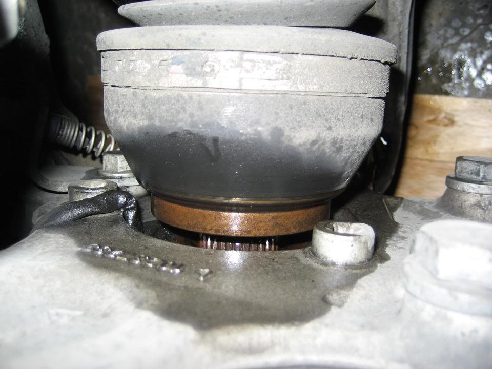
16) Its now time to drill the holes for the rubber expansion nuts or whatever you decided to use. I'm sure you could also use self tapping bolts if you can managed to get space between the window and ratchet. Place the projector in into its seat pushing it all the way towards the front of the car. Mark the 2 holes with a marker or whatever you can manage to get between the window. Also mark the column support on the pre 99 cars for the 3rd mount. The 99+ cars should already have the cutout for the screw to reside in. Remove the projector and drill. Once drilled, mount the projector with whatever method you chose.

17) Once the dash pad is out, you can flip it over and see where you�re supposed to cut. Cut to the very edge of the sides, and about a 1/4" from the bottom (Front of dash closest to steering wheel) to provide a step for the bezel to grip the dash pad. Cut slowly, KEEP cutting device perpendicular to cut while watching where the bezel rests. This is the most time consuming part of the install. Cut little by little constantly fitting bezel until snug. Cut the foam and pad with a sharp razor blade. TAKE YOUR TIME, you don't want to know what a replacement dash pad costs!!! (My diagram is for illustration purposes only)

18) Once you have the hole trimmed to fit the bezel, fit the bezel in place and hold it with some clamps. Make sure the bezel is flush with the rear edge of the dash (side under/closest to windshield) You can choose your own method to secure it to the dash pad. I mixed up a batch of JB Quick Weld filled the holes, glued the front tabs of the bezel, removed the clamps and was done. One of my customers cut the legs by enough to use screws into the legs.

19) While your waiting for your bezel to set you can use swap your stock 97-99 non-HUD cluster with the reprogrammed HUD enabled cluster, or to add the HUD switch and wiring harness to your HUD enabled cluster. To remove the cluster from the car with the dash pad already removed you need to remove 2, 7mm screws located just below the cluster and reach behind the cluster and pinch the large grey connector while pulling, rocking or whatever else it take to get it loose.

� 19a.) If your cluster came from a car with HUD already installed, install your new cluster and move to step 20
� 19b.) If you have a HUD enabled cluster that came from a car without HUD you will have to purchase a HUD switch from the dealer and swap it with your existing dimmer switch. If you can find a factory wiring harness, just plug it in, install and move to step 20


Putting your Vette back together
20) Congratulations take a step back and look at the mess you've created. Maybe have a drink or two, because reinstalling it all is the easiest and fastest part.
21) Plug in the main cluster harness, and now the HUD projector harness to the back of the cluster. Key the ignition on and make sure everything works. All the gauges should do they're full sweep as well as the projection on the windshield should do similar.
� Play with the intensity, make sure it gets bright, dims, disappears...
� Cycle through the page button, to switch displayed fuel level, coolant temperature, oil pressure, also hold it briefly to switch Tach on/off cycling through the different views.
� Also move the display up and down the window to make sure everything is hooked up correctly.
� If everything appears to work correctly move on to step 22. (make sure you firmly plugged in the fuel buttons on the right if you installed the HUD switch)
22) Re-install the 2, 7mm screws holding the lower cluster in.
23) Don't forget the sensor, and wire harness you disconnected from the defroster grill. Tape them up to the defroster so they will be accessible when you reinstall the pad
24) Get your helper grab the now "HUD enabled" dash pad and move it back into place. Before pushing it all the way back toward the window, make sure to hook up the hazard switch. (Forget to do this and your turn signals will not work)
25) Re-install the various 7mm screws you removed throughout, not forgetting:
� 2 under the defroster vent,
� 2 off to the side/under the pillars,
� the one on the side near the passenger hinge area.
26) Re-install the 2, T15 screws above the cluster to dash pad
27) Re-install the side pillars by starting in the bottom, and working to the top
28) Re-install the stereo with 2, 7mm screws
29) Re-install the glove box, get all the 7mm screws, and 2, 10mm bolts in loosely before tightening everything down
30) Re-install the center console not forgetting to hook up all electrical connections
31) Re-install the shift ****/selector
32) Sit back and take a look at a job well done, hopefully there will be no mysterious screws left over.
http://home.comcast.net/~joshker99/hudinstall2.htm
Unfortunately that link no longer works. 2000-C5 however, saved a copy of it and emailed me a word document of it. I decided to upload all the pics and instructions and I'm reposting it here. If someone wants a copy of the word document, please feel free to email me.
I don't know what happened to Josh's site and Josh, if you don't want me to host this info, please let me know and I'll delete it. ***I take NO CREDIT FOR THIS INFO!!! Josh did all the work on this, I'm just posting it!***I put this on my website as well, but I wanted a working copy for the forum so I put the whole thing here so if someone searches for 'dash removal' they'll find everything right here. Also, the forum only allows 25 pics to be uploaded and there were 27 total so I removed some of the pics showing the different HUD display options as they aren't that important. Ok ok ok...enough talkin...here is the instructions
For those not familiar with heads up display, You get 9 different ways to project critical info on your windshield, like speed, Tach, gas level, oil pressure, coolant temp, turn signals, high beam indicator, shift light indicator (6 Speeds) and check gages. You can control which are displayed, adjust the height of the projection on the windshield, and the intensity. Some are shown here:
Heads up display wasn�t even offered until late 99, but for those who were not fortunate enough to get this way cool option here's the directions to install it yourself. It can even be retrofitted in a 97,98, Early 99, and 01 Z06 Corvette when it wasn't even an option. Its plug and play. Any confident installer can install it within an afternoon. The factory HUD cars have a special HUD windshield that is not necessary as the projections shown above are taken on my non-HUD glass in direct sunlight. Also all 97+ C5's have the pocket for the projector, and the outline for the dash to be cut.
The following are the necessary components needed HUD to work
� HUD projector - 10279814 - (GM LIST: $1,118.82) You will have to drill 2 small holes in the dash to mount it. Even the 97,'s and 98's have the seat for the projector
� HUD Projector Bezel - 10425223 - (GM LIST: $25.52) You will have to cut a hole in the dash and the bezel is there to cover the hole. Its very easy to do though because even the 97 and 98's have the cut marked out under the dash pad. The bezel simply covers the hole.
� HUD Enabled Cluster � This is a must for a 97-99 owner that currently doesn�t have a HUD enabled cluster. The cluster may be HUD ready or it could have come from a HUD equipped car. If it is only HUD ready you will need a HUD switch and 11 pin wiring harness.
� HUD Switch - Part # 12198648 (GM LIST: $124.04)
� The very important 11 Pin wiring harness which is not available from GM, you will have to find a harness, or you will have to build your own using your existing harness.
There are 2 different HUD install scenario's.
97, 98, or early 99 C5's without the HUD enabled cluster - You will need to get a late 99+ Cluster. The only way to tell whether you have the HUD enabled cluster is to remove the one you have and look for the white connector in the very back. If it doesn't already have the HUD Switch you will have to install one and find a 11 pin harness. If you need a HUD enabled cluster you will have to have it programmed with your existing mileage. I've heard ~$50 to do this, but contact your dealer. You will have to drill 3 holes to mount the projector, 2 in the plastic dash support, 1 in the aluminum column support. If you use a late 99-04 cluster you will also have to move the airbag warning light located next to the fuel gauge to the location on the Tach or else the light will remain lit al the time.
Late 99-04 C5's with a HUD enabled cluster - You will need the projector, dash bezel, switch and 11 Pin from the switch to cluster. You will have to drill only 2 holes in the plastic dash support, the third is already notched out.
Tools Necessary:
� A small assortment of flat headed screw drivers.
� Very sharp razor Blades
� Something to cut the plastic under the dash pad (Dremel tool, utility knife, angle grinder etc...)
� Something to drill mounting holes (I used a right angle electric screw driver with a 1/8" conical grinding bit)
� Torx T15 driver, or bit with compatible holder to use with 1/4" ratchet.
� 7mm socket and driver
� 10mm Socket with swivel and various extensions
� 1/4 ratchet for the 7mm socket
� Needle nose pliers
� 2 #10 rubber expansion nuts available from home improvement store (Lowe's, Home depot, Ace, Etc....)
� 2 Allen Screws for the expansion nuts. With proper Allen wrench.
� JB Quick Weld or similar to affix the bezel
� Clamps or similar to hold bezel
The install is pretty basic. If you have a roadster or coupe now is a great time to open the car up. This is also a great time to move both seats all the way back to allow your self plenty of room to work. I myself just completed this modification on my own 2000 Corvette on 8/5/03 and the pictures seen here are from my own install. These instructions are for a 2000 six speed coupe
Removing the Center Console:
1)Remove the center console. To do this you will need to open the console remove the little covers in the rear of the console to access the 2,10mm nuts. Remove these.
2) Move up towards the front of the console bin. Insert a flat headed screw driver or similar to pop off the panel with the Traction Control / Active Handling.
3) Disconnect all wiring.
4) Remove the 2, 10mm nuts under the cover, at this point you need to disconnect the fuel door switch and the rear center console is ready to be removed.
5) To remove the front half you will need to remove the shifter ****, and pull out the ash tray.
5a.) To remove the shifter ****, first pry the black shift pattern diagram. Then you will need a pair of needle nose pliers or similar to pull the key out of the shaft before being able to spin the **** off. I'm assuming the A4 has a clip in the front of the **** that has to be pulled straight out before pulling off the ****.
6) There are 3, Torx 15 screws holding the front of the console in. These are located
� 1. Under the temperature sensor panel, located to the right of the steering wheel. Pop off the bezel with a flat headed screw driver. Disconnect the air temperature sensor (If equipped with the dual climate)
� 2. to the Left of the cigarette lighter
� 3. behind the ash tray
7) At this point the center console pulls straight off. There are a few clips that still hold it in around the radio and climate control. Don't forget to disconnect the cigarette lighter by reaching around the back and pulling the connector off. With the center console completely removed, you are now ready to work on the panel under the steering column.
Preparing for Dash Pad Removal
8) Start by removing the Trunk release/fog light switch bezel, with a flat headed screw driver, disconnect wires. Remove the Torx 15 screw. Remove the 2, T15 screws located up top of the instrument panel directly above the steering wheel
9) Look under the dash, towards the rear and remove the 2 T15 screws. At this point you�re ready to remove the lower steering column cover. Simply pull evenly towards the steering wheel; there are 2 clips that hold near the left hand upper corner.
10) You will need to remove the radio to help reach the hazard switch to disconnect when you start to remove the dash pad. Remove the 2, 7mm screws on each side of the radio and slide it out disconnecting all connectors from the back of the radio.
11) Take a flat headed screw driver and gently pry the defroster vent grill, Disconnect the sensor on the left side and twist the sensor loose on the right, now take your 7mm 1/4 ratchet and remove the 2 screws to the outsides of the defroster
12) Remove the side pillars. To do this start from the top and pull towards the rear/center of the vehicle. Move down the pillar, there are 3 clips to completely disengage the pillars.
13) You are now ready to remove the rest of the dash pad 7mm screws. There are 2 on the top on the sides of the dash pad that were covered by the pillars. There is one on the passenger side of the dash near the hinge of the door, (look at the side of the dash with the door fully open) one near where the cluster resides on the drivers side, and the rest are visible around the stereo was
15) Once all the screws are removed from the dash pad, gently pull the dash pad away from the window. Once moved enough disconnect the hazard switch connector. This is where you�re going to probably want a helper. Finish pulling the dash out of the car.
Preparing for HUD installation
16) Its now time to drill the holes for the rubber expansion nuts or whatever you decided to use. I'm sure you could also use self tapping bolts if you can managed to get space between the window and ratchet. Place the projector in into its seat pushing it all the way towards the front of the car. Mark the 2 holes with a marker or whatever you can manage to get between the window. Also mark the column support on the pre 99 cars for the 3rd mount. The 99+ cars should already have the cutout for the screw to reside in. Remove the projector and drill. Once drilled, mount the projector with whatever method you chose.
17) Once the dash pad is out, you can flip it over and see where you�re supposed to cut. Cut to the very edge of the sides, and about a 1/4" from the bottom (Front of dash closest to steering wheel) to provide a step for the bezel to grip the dash pad. Cut slowly, KEEP cutting device perpendicular to cut while watching where the bezel rests. This is the most time consuming part of the install. Cut little by little constantly fitting bezel until snug. Cut the foam and pad with a sharp razor blade. TAKE YOUR TIME, you don't want to know what a replacement dash pad costs!!! (My diagram is for illustration purposes only)
18) Once you have the hole trimmed to fit the bezel, fit the bezel in place and hold it with some clamps. Make sure the bezel is flush with the rear edge of the dash (side under/closest to windshield) You can choose your own method to secure it to the dash pad. I mixed up a batch of JB Quick Weld filled the holes, glued the front tabs of the bezel, removed the clamps and was done. One of my customers cut the legs by enough to use screws into the legs.
19) While your waiting for your bezel to set you can use swap your stock 97-99 non-HUD cluster with the reprogrammed HUD enabled cluster, or to add the HUD switch and wiring harness to your HUD enabled cluster. To remove the cluster from the car with the dash pad already removed you need to remove 2, 7mm screws located just below the cluster and reach behind the cluster and pinch the large grey connector while pulling, rocking or whatever else it take to get it loose.
� 19a.) If your cluster came from a car with HUD already installed, install your new cluster and move to step 20
� 19b.) If you have a HUD enabled cluster that came from a car without HUD you will have to purchase a HUD switch from the dealer and swap it with your existing dimmer switch. If you can find a factory wiring harness, just plug it in, install and move to step 20
Putting your Vette back together
20) Congratulations take a step back and look at the mess you've created. Maybe have a drink or two, because reinstalling it all is the easiest and fastest part.
21) Plug in the main cluster harness, and now the HUD projector harness to the back of the cluster. Key the ignition on and make sure everything works. All the gauges should do they're full sweep as well as the projection on the windshield should do similar.
� Play with the intensity, make sure it gets bright, dims, disappears...
� Cycle through the page button, to switch displayed fuel level, coolant temperature, oil pressure, also hold it briefly to switch Tach on/off cycling through the different views.
� Also move the display up and down the window to make sure everything is hooked up correctly.
� If everything appears to work correctly move on to step 22. (make sure you firmly plugged in the fuel buttons on the right if you installed the HUD switch)
22) Re-install the 2, 7mm screws holding the lower cluster in.
23) Don't forget the sensor, and wire harness you disconnected from the defroster grill. Tape them up to the defroster so they will be accessible when you reinstall the pad
24) Get your helper grab the now "HUD enabled" dash pad and move it back into place. Before pushing it all the way back toward the window, make sure to hook up the hazard switch. (Forget to do this and your turn signals will not work)
25) Re-install the various 7mm screws you removed throughout, not forgetting:
� 2 under the defroster vent,
� 2 off to the side/under the pillars,
� the one on the side near the passenger hinge area.
26) Re-install the 2, T15 screws above the cluster to dash pad
27) Re-install the side pillars by starting in the bottom, and working to the top
28) Re-install the stereo with 2, 7mm screws
29) Re-install the glove box, get all the 7mm screws, and 2, 10mm bolts in loosely before tightening everything down
30) Re-install the center console not forgetting to hook up all electrical connections
31) Re-install the shift ****/selector
32) Sit back and take a look at a job well done, hopefully there will be no mysterious screws left over.
08-09-2008, 06:50 AM
#40
Burning Brakes

Member Since: Sep 2006
Location: Chicago South Side
Posts: 825
Likes: 0
Received 0 Likes
on
0 Posts

Last edited by cmeflibi; 08-09-2008 at 06:54 AM.

