
How to replace the (p1416) air check valve??

 07-11-2007, 01:02 AM
#42
Tech Contributor


Member Since: Dec 1999
Location: Anthony TX
Posts: 32,736
Received 2,180 Likes
on
1,583 Posts
CI 6,7,8,9,11 Vet
St. Jude Donor '08

I dont understand your question? What end??? It starts here:
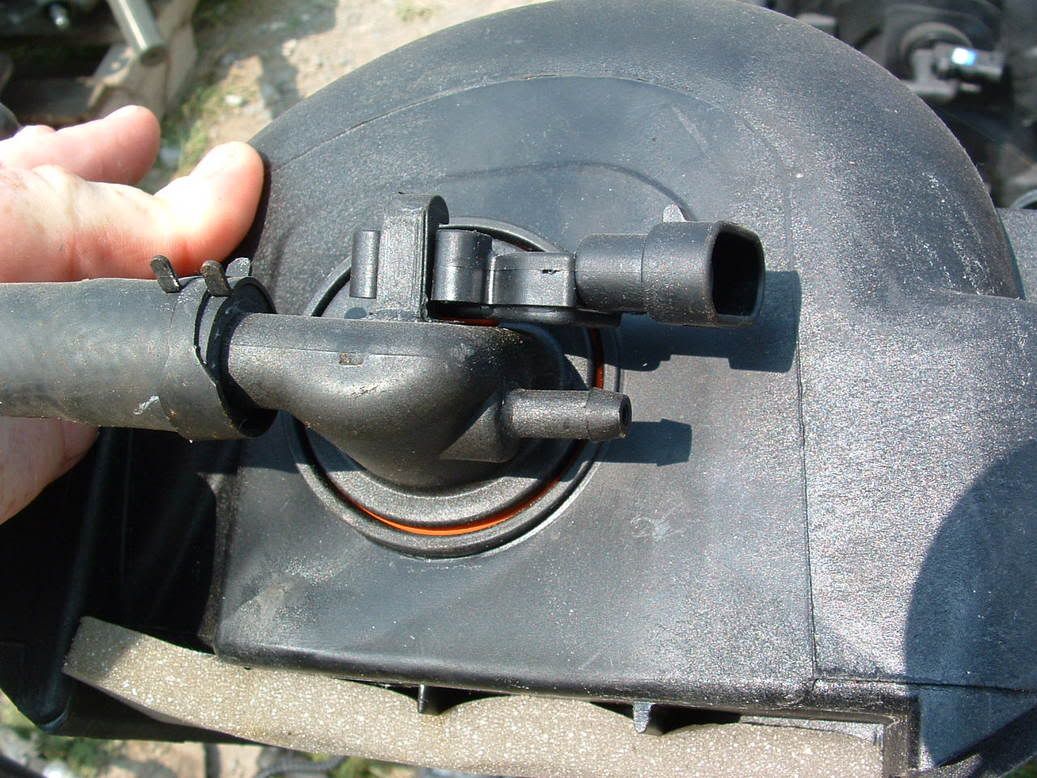
Goes down to here (RESVIOUR):
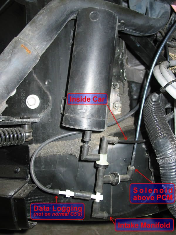
From the resivour,,,it goes to two places:
The AIR SYSTEM :

AND
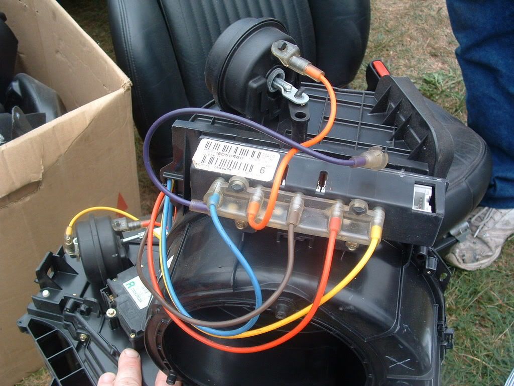
The HVAC System:
Thats it!

The following users liked this post:
rriddle (08-23-2016)
 07-11-2007, 05:18 PM
#44
Instructor

Member Since: Jul 2005
Location: Houston TX
Posts: 196
Likes: 0
Received 0 Likes
on
0 Posts

Thanks for posting the additional pictures, and sorry for not being more clear with my question. I was referring to the vacuum line that runs to the air pump, but your photos of the entire system are awesome. Thanks again they helped a lot.
Kevin
Kevin
07-19-2007, 08:37 PM
#45
Burning Brakes

Member Since: Oct 2003
Location: Foresters Falls(near Ottawa) Ont
Posts: 1,106
Likes: 0
Received 1 Like
on
1 Post

Thanks for the idea Bill!!
RonJ ...
07-25-2007, 07:45 PM
#46
Advanced
I know that this is a little late for this post but I to have the same problem with the passenger side valve being stuck open. Forgive my ignorance but why does a code set if the valve is stuck open ? Please explain to help me become smarter.
thanks
thanks
08-21-2007, 04:26 AM
#47
Intermediate

Member Since: Jul 2007
Posts: 49
Likes: 0
Received 0 Likes
on
0 Posts
Well, I cleaned the valves about a week ago using some intake manifold cleaner that I had. I made sure it was O2 sensor friendly and then almost filled the hose going to the passenger side valve, let it sit for 30 minutes, blew it with an air hose and then started it up. Glad to say that I haven't had CHECK ENGINE light up since cleaning the valves.
Thanks for the idea Bill!!
RonJ ...
Thanks for the idea Bill!!
RonJ ...
Also, can you manually clear a code w/out an obdII scanner or tuner?
08-21-2007, 06:42 AM
#48
Burning Brakes
Member Since: Oct 2003
Location: Foresters Falls(near Ottawa) Ont
Posts: 1,106
Likes: 0
Received 1 Like
on
1 Post
Go to: http://forums.corvetteforum.com/show...=trouble+codes for the info you need to do this.
I'd suggest that you print out these instructions for future use, they are useful!!
RonJ ...
08-21-2007, 12:06 PM
#49
Intermediate
Member Since: Jul 2007
Posts: 49
Likes: 0
Received 0 Likes
on
0 Posts
You should clear the code manually, you don't need a scanner to do it.
Go to: http://forums.corvetteforum.com/show...=trouble+codes for the info you need to do this.
I'd suggest that you print out these instructions for future use, they are useful!!
RonJ ...
Go to: http://forums.corvetteforum.com/show...=trouble+codes for the info you need to do this.
I'd suggest that you print out these instructions for future use, they are useful!!
RonJ ...
10-26-2007, 06:10 PM
#50


I have been getting the P1416 code for 2 weeks everyday now after clearing it each time.
I disconnected the hose coupler coming off the air pump on the inner fender well and then undid and blocked the drivers side check valve hose. This allowed full spray to only go to the other behind the intake check valve. I bought a can of O2 sensor safe throttle body cleaner and sprayed for about 20 seconds into the hose filling it up pretty good. Then took my air nozzle and blasted about 50 psi into it a couple times to force it up to the check valve real good and through it. Then I chased that with same amount of WD-40 about 10 minutes later and blew it through and let it sit overnight.
No code so far for a week now. Looks like it worked!
10-31-2007, 08:52 PM
#51
Tech Contributor
Member Since: Dec 1999
Location: Anthony TX
Posts: 32,736
Received 2,180 Likes
on
1,583 Posts
CI 6,7,8,9,11 Vet
St. Jude Donor '08
Its getting cold again in some areas. This time of the year the check valves can stick shut. TTT
Last edited by Bill Curlee; 04-02-2008 at 09:48 PM.
04-02-2008, 09:55 PM
#52
Tech Contributor
Member Since: Dec 1999
Location: Anthony TX
Posts: 32,736
Received 2,180 Likes
on
1,583 Posts
CI 6,7,8,9,11 Vet
St. Jude Donor '08
Time to push this to the top. A couple of people have asked to see it. I added the write up on DTC 0410:
BC
Circuit Description
An AIR pump is used on this vehicle to lower tail pipe emissions on start-up. The PCM supplies a ground to the AIR pump relay, which energizes the AIR pump.
The PCM monitors the HO2S voltages to diagnose the AIR system.
During the AIR test, the PCM activates the AIR pump during closed loop operation. When the AIR is activated, the PCM monitors the HO2S voltages and short term fuel trim values for both banks of the engine. If the AIR system is operating properly, the HO2S voltages should go low and the short term fuel trim should go high.
If the PCM determines that the HO2S voltages for both banks did not respond as expected during the tests, DTC P0410 sets. If only one sensor responded, the PCM sets either a DTC P1415 or P1416 to indicate on which bank the AIR system is inoperative.
Conditions for Running the DTC
DTCs P0101, P0102, P0103, P0107, P0108, P0112, P0113, P0117, P0118, P0125, P0171-P0175, P0200, P0300, P0335, P0336, P0351-P0358, P0440, P0442, P0443, P0446, P0449, P1120, P1220, P1221, P1258, P1441 and HO2S DTCs are not set.
Fuel level greater than 12.5 percent but less than 87.5 percent.
The engine is running for greater than 2.0 seconds.
The maximum air flow is 25 g/s.
The air fuel ratio is 14.7:1
The engine load is less than 34 percent.
The ignition voltage is greater than 11.7 volts.
Engine is not operating in Power Enrichment, Decel Fuel Shut-off, or Catalyst Over-Temperature modes.
The engine is operating in closed loop for greater than 15 seconds.
The engine speed is greater than 718 RPM.
The ECT is greater than 80�C (176�F) but less than 110�C (230�F).
The IAT is greater than -2�C (28.4�F).
The fuel system is operating in fuel trim cells 1, 2, 4, 5, or 6.
Conditions for Setting the DTC
The HO2S voltage does not go below 222 mV for 1.3 seconds, when the AIR pump turns ON during closed loop operation.
OR
The short term fuel trim does not change more than a predetermined value, when the AIR pump turns ON during closed loop operation.
Action Taken When the DTC Sets
The PCM illuminates the malfunction indicator lamp (MIL) on the second consecutive ignition cycle that the diagnostic runs and fails.
The PCM records the operating conditions at the time the diagnostic fails. The first time the diagnostic fails, the PCM stores this information in the Failure Records. If the diagnostic reports a failure on the second consecutive ignition cycle, the PCM records the operating conditions at the time of the failure. The PCM writes the conditions to the Freeze Frame and updates the Failure Records.
Conditions for Clearing the MIL/DTC
The PCM turns OFF the malfunction indicator lamp (MIL) after 3 consecutive ignition cycles that the diagnostic runs and does not fail.
A last test failed, or current DTC, clears when the diagnostic runs and does not fail.
A history DTC clears after 40 consecutive warm-up cycles, if no failures are reported by this or any other emission related diagnostic.
Use a scan tool in order to clear the MIL and the DTC.
Diagnostic Aids
Important
Remove any debris from the PCM connector surfaces before servicing the PCM. Inspect the PCM connector gaskets when diagnosing/replacing the module. Ensure that the gaskets are installed correctly. The gaskets prevent contaminate intrusion into the PCM.
For any test that requires probing the PCM or a component harness connector, use the Connector Test Adapter Kit J 35616-A . Using this kit prevents damage to the harness/component terminals. Refer to Using Connector Test Adapters in Wiring Systems.
AIR Pump Relay Underhood Electrical Center Terminal Identification
Front of Vehicle
Left Side of Vehicle
Ignition
B+
Right Side of Vehicle
Load
Control
If DTCs P0412 or P0418 are not set and the relay or solenoid does not respond to the scan tool commands, inspect for excessive resistance in all of the circuits associated with the AIR system.
For an intermittent, refer to Symptoms .
Test Description
The numbers below refer to the step numbers on the diagnostic table.
If DTCs P0412 or P0418 are set, diagnose those DTCs first.
The scan tool offers three modes of AIR operation, AIR solenoid, AIR pump, and AIR system. Use the AIR system selection when commanding the AIR pump, or relays. This mode ensures that the entire AIR system is responding to the scan tool commands. If DTCs P0412 or P0418 are not set and the relay or solenoid does not respond to the scan tool commands, inspect for excessive resistance in all of the circuits associated with the AIR system.
This step is testing for battery voltage at the AIR pump relay.
This step is testing for power to the AIR pump.
This step is testing the ground circuit for the AIR pump.
This step is testing for a grounded circuit between the AIR pump and the AIR pump relay.
A restriction in a hose or pipe before the systems divides will cause this DTC to set. Inspect for kinks or blockages from the AIR pump to the connection point where the AIR system divides.
DTC P0410 - Secondary Air Injection (AIR) System Step
Action
Values
Yes
No
1
Did you perform the Powertrain On-Board Diagnostic (OBD) System Check?
--
Go to Step 2
Go to Powertrain On Board Diagnostic (OBD) System Check
2
Is the AIR pump fuse OK?
--
Go to Step 3
Go to Step 11
3
Are DTCs P0412 or P0418 set?
--
Go to Applicable DTC table
Go to Step 4
4
Turn ON the ignition with the engine OFF.
Enable the AIR system with a scan tool.
Does the AIR pump turn ON?
--
Go to Step 8
Go to Step 5
5
Turn OFF the ignition.
Disconnect the AIR pump relay.
Probe the relay B+ supply circuit at the underhood electrical center with the test lamp J 34142-B connected to ground. Refer to Diagnostic Aids for terminal identification.
Does the test lamp illuminate?
--
Go to Step 6
Go to Step 16
6
Install the AIR pump relay.
Disconnect the AIR pump electrical connector. Refer to Secondary AIR Injection Pump Replacement .
Probe terminal A of the AIR pump electrical connector using the test lamp J 34142-B connected to battery ground. Refer to Probing Electrical Connectors in Wiring Systems.
Turn ON the ignition with the engine OFF.
Enable the AIR system with a scan tool.
Does the test lamp illuminate?
--
Go to Step 7
Go to Step 17
7
Probe terminal B of the AIR pump electrical connector with the test lamp J 34142-B connected to B+.
Is the test lamp illuminated?
--
Go to Step 27
Go to Step 18
8
Turn OFF the ignition.
Disconnect the AIR pump outlet hose from the AIR pump. Refer to Secondary AIR Injection Pump Replacement .
Turn ON the ignition with the engine OFF.
Enable the AIR system with a scan tool.
Is air flow present at the AIR pump outlet?
--
Go to Step 9
Go to Step 10
9
Turn OFF the ignition.
Disconnect the vacuum hose from the AIR Shut Off Valve.
Start the engine.
Enable the AIR solenoid with a scan tool.
Is a vacuum present at the AIR Shut Off valve?
--
Go to Step 14
Go to Step 19
10
Inspect for a restriction/blockage in the AIR Pump inlet hoses/pipes.
If you find a restriction/blockage in the AIR hoses/pipes, repair as necessary.
Did you find and correct the condition?
--
Go to Step 29
Go to Step 28
11
Turn OFF the ignition.
Disconnect the AIR pump relay.
Probe the AIR pump relay B+ supply terminal at the underhood electrical center using the test lamp J 34142-B connected to B+. Refer to Probing Electrical Connectors in Wiring Systems. Refer to Diagnostic Aids for terminal identification.
Does the test lamp illuminate?
--
Go to Step 23
Go to Step 12
12
Disconnect the AIR pump electrical connector. Refer to Secondary AIR Injection Pump Replacement .
Probe the AIR pump relay load terminal at the underhood electrical center using the test lamp J 34142-B connected to B+. Refer to Diagnostic Aids for terminal identification.
Does the test lamp illuminate?
--
Go to Step 24
Go to Step 13
13
Install the AIR pump electrical connector.
Install a new fuse.
Install the AIR pump relay.
Turn ON the ignition with the engine OFF.
Enable the AIR system with a scan tool.
Does the fuse open?
--
Go to Step 28
Go to Diagnostic Aids
14
Install the following components:
AIR pump outlet hose to AIR pump.
Vacuum hose to AIR Shut Off Valve.
Disconnect the AIR Shut Off Valve outlet hose.
Start and idle the engine.
Enable the AIR system with a scan tool.
Is air present at the outlet of the AIR Shut Off Valve?
--
Go to Step 22
Go to Step 15
15
Replace the AIR Shut Off Valve. Refer to Secondary AIR Injection Shut Off Valve Replacement .
Is the action complete?
--
Go to Step 29
--
16
Repair the open circuit that did illuminate the test lamp. Refer to Wiring Repairs in Wiring Systems.
Is the action complete?
--
Go to Step 29
--
17
Test for continuity of the circuit between the AIR pump electrical connector terminal A and the AIR pump relay using the DMM . Refer to Testing for Continuity in Wiring Systems.
If you find an open circuit repair the circuit as necessary. Refer to Wiring Repairs in Wiring Systems.
Did you find and correct the condition?
--
Go to Step 29
Go to Step 25
18
Repair the faulty ground connection or open AIR pump ground circuit. Refer to Wiring Repairs in Wiring Systems.
Is the action complete?
--
Go to Step 29
--
19
Turn OFF the ignition.
Disconnect the source vacuum hose from the AIR Solenoid Valve. Refer to AIR Solenoid Valve Replacement .
Start and idle the engine.
Is a vacuum present at the AIR Solenoid Valve?
--
Go to Step 20
Go to Step 21
20
Turn OFF the ignition.
Connect the source vacuum hose to the AIR Solenoid Valve.
Disconnect the vacuum hose to the AIR Shut Off Valve at the AIR Solenoid Valve.
Start and idle the engine.
Enable the AIR Solenoid Valve with a scan tool.
Is a vacuum present at the AIR Solenoid Valve outlet?
--
Go to Step 21
Go to Step 26
21
Repair the restriction/blockage or damage to the vacuum hose.
Is the action complete?
--
Go to Step 29
--
22
Repair the restriction/blockage or disconnect in the AIR hose between the AIR Shut Off Valve and the point where the system branches to both side of the engine.
Is the action complete?
--
Go to Step 29
--
23
Repair the short to ground in the ignition feed circuit between the fuse and the relays. Refer to Wiring Repairs in Wiring Systems.
Is the action complete?
--
Go to Step 29
--
24
Repair the short to ground in the circuit between the AIR pump relay and the AIR pump. Refer to Wiring Repairs in Wiring Systems.
Is the action complete?
--
Go to Step 29
--
25
Replace the AIR pump relay. Refer to Secondary Air Injection Pump Relay Replacement .
Is the action complete?
--
Go to Step 29
--
26
Replace the AIR Solenoid Valve. Refer to AIR Solenoid Valve Replacement .
Is the action complete?
--
Go to Step 29
--
27
Inspect for poor connections at the AIR pump electrical connector. Refer to Testing for Intermittent and Poor Connections in Wiring Systems.
If you find a poor connection repair the terminal as necessary. Refer to Repairing Connector Terminals in Wiring Systems.
Did you find and correct the condition?
--
Go to Step 29
Go to Step 28
28
Replace the AIR pump. Refer to Secondary AIR Injection Pump Replacement .
Is the action complete?
--
Go to Step 29
--
29
Select the Diagnostic Trouble Codes (DTC) option and the Clear DTC Information option using the scan tool.
Start the engine and idle at the normal operating temperature.
Select the Specific DTC option under the Diagnostic Trouble Code (DTC) option using a scan tool.
Operate vehicle within the Conditions for Running this DTC as specified in the supporting text, if applicable.
Does the scan tool indicate that this test failed?
--
Go to Step 2
Go to Step 30
30
Select the Capture Info option and the Review Info option using the scan tool.
Are any DTCs displayed that you have not diagnosed?
--
Go to the applicable DTC table
System OK
--------------------------------------------------------------------------------
Last edited by Bill Curlee; 04-02-2008 at 10:00 PM.
The following users liked this post:
MilsteadGC (09-08-2021)
04-09-2008, 11:29 AM
#53
Intermediate
Member Since: Aug 2007
Location: Carpentersville IL
Posts: 30
Likes: 0
Received 0 Likes
on
0 Posts
Bill, just wanted to say thanks for all the hard work and pictures that you have put up. I love coming to this forum for references instead of going to the dealership.


 04-27-2008, 05:23 PM
#56
I'm "Apache" a psycho dog

Bill, thanks for the very informative post, i have used Seafoam aerosol spray in the hose and valve itself, letting it soak a bit then drive 
06-02-2008, 08:35 PM
#57
Safety Car

Member Since: Jul 2007
Location: We've gone on holiday by mistake
Posts: 4,579
Likes: 0
Received 0 Likes
on
0 Posts
I dug this up because I was getting a P0492 code. This is fantastic stuff here. But one question. Do you spray the carb cleaner in the hoses when the engine is running?
06-02-2008, 10:13 PM
#58
Tech Contributor
Member Since: Dec 1999
Location: Anthony TX
Posts: 32,736
Received 2,180 Likes
on
1,583 Posts
CI 6,7,8,9,11 Vet
St. Jude Donor '08
NO. Add the cleaner when the engine is OFF and blast it through the rubber hose with compressed air. You can run the engine with the hose disconnected and you should NOT see any exhaust pressure excape through the rubber hose. If you do,,,the check valve is stuck open or damaged beyond repair.
If you start the engine from a cold condition, you should see air exiting the hose from the AIR pump.
If you start the engine from a cold condition, you should see air exiting the hose from the AIR pump.

