
Who supplies power to the Class 2 Serial Data buss?
 05-12-2006, 11:59 PM
#1
Drifting


Thread Starter
Member Since: Oct 2004
Location: Southwest Virginia
Posts: 1,383
Likes: 0
Received 6 Likes
on
6 Posts

Which module(s) supply power to the Class 2 serial data buss?
My buss is dead and nothing is communicating.


My buss is dead and nothing is communicating.

 05-13-2006, 04:33 PM
#3
Tech Contributor


Member Since: Dec 1999
Location: Anthony TX
Posts: 32,736
Received 2,182 Likes
on
1,585 Posts
CI 6,7,8,9,11 Vet
St. Jude Donor '08

Z
I don't think that the serial buss is powered!! Each module is connected to the buss. The BCM controls the data flow and each module sends a state of health message out on the buss to tell each of the other modules that it is functioning properly.
I helped COLONEMAN fix this problem a month or so ago. We got DEEP into the serial buss thing!! Come to find out, there are a lot of things that can cause this problem!! We figured out that he had a corroded seat control module connector which was grounding the serial buss! Once we fixed that, everything worked fine.
Try this:
Read the data link connector (under the dash on the drivers side) pin #2 to ground. See what it reads.
You can disconnect STAR Connector#2 (it is the smaller one of the two star connectors)which connects the LDCM, RDCM and Seat Control Modules to the rest of the buss. If you disconnect that STAR Buss jumper and the rest of the modules work normally, you have a problem on that buss and can work in a much narrower area! The other STAR connector connects the rest of the modules together.
The STAR Connectors in the passengers foot well, just inboard the BCM can be unplugged by removing the jumper buss bar from each connector. If you read each wire to ground, each module should read some resistance that is very close to each of the others. If you read on and it reads close to or zero ohms, something is wrong with that module. I had him disconnect each module one at a time until the ground went away.
Please let me know how you make out!!
Bill C
I don't think that the serial buss is powered!! Each module is connected to the buss. The BCM controls the data flow and each module sends a state of health message out on the buss to tell each of the other modules that it is functioning properly.
I helped COLONEMAN fix this problem a month or so ago. We got DEEP into the serial buss thing!! Come to find out, there are a lot of things that can cause this problem!! We figured out that he had a corroded seat control module connector which was grounding the serial buss!
Once we fixed that, everything worked fine.Try this:
Read the data link connector (under the dash on the drivers side) pin #2 to ground. See what it reads.
You can disconnect STAR Connector#2 (it is the smaller one of the two star connectors)which connects the LDCM, RDCM and Seat Control Modules to the rest of the buss. If you disconnect that STAR Buss jumper and the rest of the modules work normally, you have a problem on that buss and can work in a much narrower area! The other STAR connector connects the rest of the modules together.
The STAR Connectors in the passengers foot well, just inboard the BCM can be unplugged by removing the jumper buss bar from each connector. If you read each wire to ground, each module should read some resistance that is very close to each of the others. If you read on and it reads close to or zero ohms, something is wrong with that module. I had him disconnect each module one at a time until the ground went away.
Please let me know how you make out!!
Bill C
05-14-2006, 09:49 AM
#4
Drifting
Thread Starter
Member Since: Oct 2004
Location: Southwest Virginia
Posts: 1,383
Likes: 0
Received 6 Likes
on
6 Posts
The data buss should be pulled to 12V by something (maybe everything) and each module who wants to talk simply pulls the buss to ground to hammer out the data it wants to communicate. The buss should idle at 12VDC the way I understand it. My guess is also the BCM should supply power since it is the master of the domain. But I have searched the manuals and no where do they seem so say how the buss gets pulled up. I know the EFILive bench harness don't have pull up resistors so either their interface pulls up the buss or the PCM pulls up the buss. Every module may have weak pullups on the buss.
My data buss reads 0VDC, cant read any codes, not comm to any device.
I know what happened, I don't know what all has been involved. Due to what I believe is a defective battery charger (have not check it yet to find out exactly what went wrong) I shot 128VAC up my data buss! I had small 6A battery charger charging the battery and I was soldering a wire on the data buss. My solder station was plugged into the same extension cord as the charger. When I touched the wire with my solder tip I got a fairly large arc which I found to be odd because shorting the buss to ground should not hurt anything since that is exactly what every module does when it talks data on the buss. After the spark I turn on the key and get "Reduced engine power" and several other messages and things obviously was not right. I checked the voltage on the buss and it was 0VDC. After sitting and thinking how could this happen I got my volt meter and measured between 12V in the lighter socket to the tip of my solder iron and it read like 20VDC, I switch to AC mode and it read 128VAC! The charger was still 14V between the positive and negative clips but for some reason there is 128VAC potential between the positive clip on the charger and the ground pin in the AC jack which caused a 128VAC difference between the 12V system in the car and my solder iron tip! Is there any lightning protection (surge protectors) on the data buss?
My BCM seems pretty dead right now, all fuses seem OK. I'm going to try to pull the buss up with a 1K resistor and see if it will come up or if it is stuck (welded) to ground somewhere. And like you said bill, guess it is best to get everything off the buss and check one by one. Exactly where are the STAR connectors located?
Thanks for the info and wish me luck, this one looks like it may get expensive!
My data buss reads 0VDC, cant read any codes, not comm to any device.
I know what happened, I don't know what all has been involved. Due to what I believe is a defective battery charger (have not check it yet to find out exactly what went wrong) I shot 128VAC up my data buss!
I had small 6A battery charger charging the battery and I was soldering a wire on the data buss. My solder station was plugged into the same extension cord as the charger. When I touched the wire with my solder tip I got a fairly large arc which I found to be odd because shorting the buss to ground should not hurt anything since that is exactly what every module does when it talks data on the buss. After the spark I turn on the key and get "Reduced engine power" and several other messages and things obviously was not right. I checked the voltage on the buss and it was 0VDC. After sitting and thinking how could this happen I got my volt meter and measured between 12V in the lighter socket to the tip of my solder iron and it read like 20VDC, I switch to AC mode and it read 128VAC! The charger was still 14V between the positive and negative clips but for some reason there is 128VAC potential between the positive clip on the charger and the ground pin in the AC jack which caused a 128VAC difference between the 12V system in the car and my solder iron tip! Is there any lightning protection (surge protectors) on the data buss? My BCM seems pretty dead right now, all fuses seem OK. I'm going to try to pull the buss up with a 1K resistor and see if it will come up or if it is stuck (welded) to ground somewhere. And like you said bill, guess it is best to get everything off the buss and check one by one. Exactly where are the STAR connectors located?
Thanks for the info and wish me luck, this one looks like it may get expensive!
05-14-2006, 10:02 AM
#5
Tech Contributor
Member Since: Dec 1999
Location: Anthony TX
Posts: 32,736
Received 2,182 Likes
on
1,585 Posts
CI 6,7,8,9,11 Vet
St. Jude Donor '08
Your NEW nick name is SPARKEY!!!!
 In all seriousness, I would disconnect everything except the PCM and the BCM and see if you can salvage them! No,,there isnt any protection on the serial buss.
If there is any voltage on the buss, it will be a 5 VDC signal that originates from each module with signal on it. Hopeful you only toasted one module and you can isolate that one. I hope you and the bank are in good standing!!
Like I said previously, pull the STAR Buss ground bar from both connectors and read each module to ground from the STAR connector to see if you get an odd ball ground reading. They should all read about the same reading (thats a guess ) If you get a weird reading, pull that module off the line!!
GOOD LUCK!!!
Bill
In all seriousness, I would disconnect everything except the PCM and the BCM and see if you can salvage them! No,,there isnt any protection on the serial buss.If there is any voltage on the buss, it will be a 5 VDC signal that originates from each module with signal on it. Hopeful you only toasted one module and you can isolate that one. I hope you and the bank are in good standing!!
Like I said previously, pull the STAR Buss ground bar from both connectors and read each module to ground from the STAR connector to see if you get an odd ball ground reading. They should all read about the same reading (thats a guess
) If you get a weird reading, pull that module off the line!!GOOD LUCK!!!
Bill
05-14-2006, 10:24 AM
#6
Tech Contributor
Member Since: Oct 1999
Location: Charlotte, NC (formerly Endicott, NY)
Posts: 40,131
Received 8,961 Likes
on
5,347 Posts
Originally Posted by SpeedyZ
The data buss should be pulled to 12V by something (maybe everything) and each module who wants to talk simply pulls the buss to ground to hammer out the data it wants to communicate. The buss should idle at 12VDC the way I understand it. My guess is also the BCM should supply power since it is the master of the domain. But I have searched the manuals and no where do they seem so say how the buss gets pulled up. I know the EFILive bench harness don't have pull up resistors so either their interface pulls up the buss or the PCM pulls up the buss. Every module may have weak pullups on the buss.
My data buss reads 0VDC, cant read any codes, not comm to any device.
I know what happened, I don't know what all has been involved. Due to what I believe is a defective battery charger (have not check it yet to find out exactly what went wrong) I shot 128VAC up my data buss! I had small 6A battery charger charging the battery and I was soldering a wire on the data buss. My solder station was plugged into the same extension cord as the charger. When I touched the wire with my solder tip I got a fairly large arc which I found to be odd because shorting the buss to ground should not hurt anything since that is exactly what every module does when it talks data on the buss. After the spark I turn on the key and get "Reduced engine power" and several other messages and things obviously was not right. I checked the voltage on the buss and it was 0VDC. After sitting and thinking how could this happen I got my volt meter and measured between 12V in the lighter socket to the tip of my solder iron and it read like 20VDC, I switch to AC mode and it read 128VAC! The charger was still 14V between the positive and negative clips but for some reason there is 128VAC potential between the positive clip on the charger and the ground pin in the AC jack which caused a 128VAC difference between the 12V system in the car and my solder iron tip! Is there any lightning protection (surge protectors) on the data buss?
My BCM seems pretty dead right now, all fuses seem OK. I'm going to try to pull the buss up with a 1K resistor and see if it will come up or if it is stuck (welded) to ground somewhere. And like you said bill, guess it is best to get everything off the buss and check one by one. Exactly where are the STAR connectors located?
Thanks for the info and wish me luck, this one looks like it may get expensive!
My data buss reads 0VDC, cant read any codes, not comm to any device.
I know what happened, I don't know what all has been involved. Due to what I believe is a defective battery charger (have not check it yet to find out exactly what went wrong) I shot 128VAC up my data buss!
I had small 6A battery charger charging the battery and I was soldering a wire on the data buss. My solder station was plugged into the same extension cord as the charger. When I touched the wire with my solder tip I got a fairly large arc which I found to be odd because shorting the buss to ground should not hurt anything since that is exactly what every module does when it talks data on the buss. After the spark I turn on the key and get "Reduced engine power" and several other messages and things obviously was not right. I checked the voltage on the buss and it was 0VDC. After sitting and thinking how could this happen I got my volt meter and measured between 12V in the lighter socket to the tip of my solder iron and it read like 20VDC, I switch to AC mode and it read 128VAC! The charger was still 14V between the positive and negative clips but for some reason there is 128VAC potential between the positive clip on the charger and the ground pin in the AC jack which caused a 128VAC difference between the 12V system in the car and my solder iron tip! Is there any lightning protection (surge protectors) on the data buss? My BCM seems pretty dead right now, all fuses seem OK. I'm going to try to pull the buss up with a 1K resistor and see if it will come up or if it is stuck (welded) to ground somewhere. And like you said bill, guess it is best to get everything off the buss and check one by one. Exactly where are the STAR connectors located?
Thanks for the info and wish me luck, this one looks like it may get expensive!
Bill
05-14-2006, 08:52 PM
#7
Drifting
Thread Starter
Member Since: Oct 2004
Location: Southwest Virginia
Posts: 1,383
Likes: 0
Received 6 Likes
on
6 Posts
Originally Posted by Bill Curlee
Your NEW nick name is SPARKEY!!!!
Thats funny!Good news! It appears the Class 2 serial data buss surge protector is the IPC (Instrument Panel Cluster)!
 The IPC has the data buss grounded at about 10 ohms. I removed the IPC from the buss and it looks like all the other modules are back home and working again.
 Seems like everything is working except I'm still getting the "Reduced engine power" on the DIC and obviously the DIC won't communicate with any modules to check codes. The codes the scanner is pulling seems to be standard codes where other parts are off the car. Pulling the IPC now, anyone got a good cheap Z06 IPC?
Sparky
05-14-2006, 09:03 PM
#8
Le Mans Master

Member Since: Sep 2003
Location: Farmington CT
Posts: 6,125
Received 160 Likes
on
125 Posts
Cruise-In VII Veteran
Originally Posted by SpeedyZ
Thats funny!Good news! It appears the Class 2 serial data buss surge protector is the IPC (Instrument Panel Cluster)!
The IPC has the data buss grounded at about 10 ohms. I removed the IPC from the buss and it looks like all the other modules are back home and working again. Seems like everything is working except I'm still getting the "Reduced engine power" on the DIC and obviously the DIC won't communicate with any modules to check codes. The codes the scanner is pulling seems to be standard codes where other parts are off the car. Pulling the IPC now, anyone got a good cheap Z06 IPC?Sparky
just transfer the display from the new unit to the Z cluster
05-14-2006, 10:09 PM
#9
Tech Contributor
Member Since: Dec 1999
Location: Anthony TX
Posts: 32,736
Received 2,182 Likes
on
1,585 Posts
CI 6,7,8,9,11 Vet
St. Jude Donor '08
Rip that module abart and see what SPARKED!!!
Might find something simple and be able to restore it.
BC
Might find something simple and be able to restore it.
BC
05-15-2006, 07:57 AM
#10
Drifting
Thread Starter
Member Since: Oct 2004
Location: Southwest Virginia
Posts: 1,383
Likes: 0
Received 6 Likes
on
6 Posts
Originally Posted by Bill Curlee
Rip that module abart and see what SPARKED!!!
Might find something simple and be able to restore it.
BC
Might find something simple and be able to restore it.
BC
Don't see no big arcs anywhere.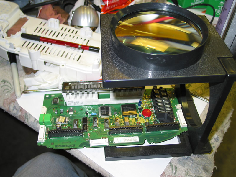
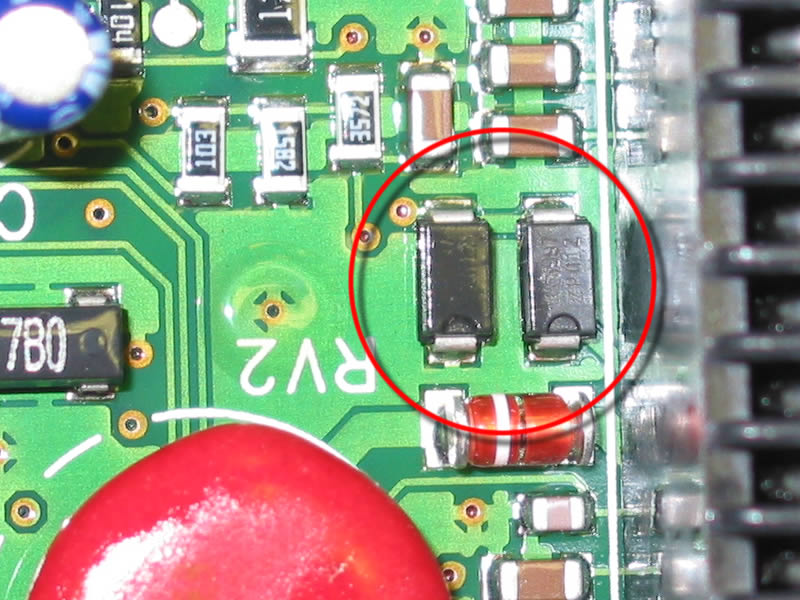
I'm suspecting one of these guys. Not sure what they are, kind of look like caps. Got a Motorola logo on them and a PR012. Both have the same number. Nothing else on the board looks like them. Hard to tell until I suck them off the board but it looks like the data goes through the one on the right, then the left of is between the data buss and ground, then through the board at the via to the upper left of the two items.
I need to find someone with a old board where they upgraded their IPC for a HUD install. Should be lots around if I could just find one.
Sparky
05-15-2006, 09:31 AM
#11
Safety Car

Member Since: May 2003
Location: Vette-hid.com Lost in DFW texas
Posts: 4,961
Likes: 0
Received 1 Like
on
1 Post
Cruise-In V Veteran
Cruise-In VI Veteran
Cruise-In VII Veteran
St. Jude Donor '06-'07
Originally Posted by SpeedyZ
Which module(s) supply power to the Class 2 serial data buss?
My buss is dead and nothing is communicating.
My buss is dead and nothing is communicating.
The pins tend to oxidize and ground out the data bus.
The harness i'm talking about is in the tube between door and door jamb
05-15-2006, 04:58 PM
#12
Tech Contributor
Member Since: Dec 1999
Location: Anthony TX
Posts: 32,736
Received 2,182 Likes
on
1,585 Posts
CI 6,7,8,9,11 Vet
St. Jude Donor '08
Looks like the one onthe left is a bit darker than the other. i googled PR012 under electrical components and got a supplier. The data base did not recongise PR012 are you sure thats the correct #???? Take a real close look at the number again. My guess,, it's a diode.
Bill
Bill
05-15-2006, 05:29 PM
#13
Drifting
Thread Starter
Member Since: Oct 2004
Location: Southwest Virginia
Posts: 1,383
Likes: 0
Received 6 Likes
on
6 Posts
Yep, it is marked PR012 (used a 12x eye loupe to be sure) but then again GM has their custom number put on everything so you don't know what they are using! At first the right one looked different but after looking close it just didn't have as much of the clear gook on it that they put on the board. I thought diode at first too, thinking two diodes back to back to limit high and low voltage, but it looks like the data buss goes through the one on the right and the left one is jumped between the buss and ground. I don't think the data buss though a diode would work since it needs to send and receive on the single wire. So I started thinking an isolation cap to prevent DC offset. Odd they would buy caps from Motorola though. You can see it is notched on one side so it looks like it makes a difference which way it is installed. I thought may zener diodes to limit the voltage levels, but they don't look like they are placed correctly for zeners. I will know more when I get them sucked off the board and see how the traces run under there. Or I should say if I get them sucked off the board. They are down between other tall stuff making them hard to access. And of course it is a multi layered board so you can't do much tracing. Leaving work now, going to go home and see what I can tear up tonight!
Sparky
At first the right one looked different but after looking close it just didn't have as much of the clear gook on it that they put on the board. I thought diode at first too, thinking two diodes back to back to limit high and low voltage, but it looks like the data buss goes through the one on the right and the left one is jumped between the buss and ground. I don't think the data buss though a diode would work since it needs to send and receive on the single wire. So I started thinking an isolation cap to prevent DC offset. Odd they would buy caps from Motorola though. You can see it is notched on one side so it looks like it makes a difference which way it is installed. I thought may zener diodes to limit the voltage levels, but they don't look like they are placed correctly for zeners. I will know more when I get them sucked off the board and see how the traces run under there. Or I should say if I get them sucked off the board. They are down between other tall stuff making them hard to access. And of course it is a multi layered board so you can't do much tracing. Leaving work now, going to go home and see what I can tear up tonight! Sparky
05-15-2006, 11:10 PM
#14
Drifting

Member Since: Feb 2000
Location: Boulder, Colorado
Posts: 1,922
Likes: 0
Received 0 Likes
on
0 Posts
Off topic, but what IS the Class 2 serial bus? Is it the OBD2 bus (VPW J1850), or something else? I write aerospace software, so I know ARINC 429, 453, 664, 708, mil std 1553, rs232, rs422, rs485, SPI, I2C, CAN, etc, but I don't know anything about automotive data busses. Which is odd, because the main one my company uses now, ByteFlight, came from BMW, and we're the only aerospace company using it.
Any place to go for docs on GM stuff? I looked for docs on OBD2, but couldn't find any free ones, and ended up buying a PIC preloaded with OBD2 <-> serial code in it, so I just sent rs232 from my uC to the PIC, and got back speed, rpm, fuel trims, O2 readings, etc, which is all I wanted at the time. It'd be cool to dig into the guts of it and be able to see all the data getting passed around.
Any place to go for docs on GM stuff? I looked for docs on OBD2, but couldn't find any free ones, and ended up buying a PIC preloaded with OBD2 <-> serial code in it, so I just sent rs232 from my uC to the PIC, and got back speed, rpm, fuel trims, O2 readings, etc, which is all I wanted at the time. It'd be cool to dig into the guts of it and be able to see all the data getting passed around.
05-15-2006, 11:42 PM
#15
Tech Contributor
Member Since: Dec 1999
Location: Anthony TX
Posts: 32,736
Received 2,182 Likes
on
1,585 Posts
CI 6,7,8,9,11 Vet
St. Jude Donor '08
The GM service manual shows a cave man schematic of how the different microprocessors are cobbled together! Thats good enough for me. I just press the "I BELIEVE" button and make it work!! When it fails, I have enough electronics background to fix it!
Your a LOT deeper into that stuff than I ever want to be but that is COOL!
Bill C
Your a LOT deeper into that stuff than I ever want to be but that is COOL!
Bill C
05-15-2006, 11:55 PM
#16
Drifting
Member Since: Feb 2000
Location: Boulder, Colorado
Posts: 1,922
Likes: 0
Received 0 Likes
on
0 Posts
Originally Posted by Bill Curlee
When it fails, I have enough electronics background to fix it!
 05-16-2006, 09:34 AM
#18
Drifting
Thread Starter
Member Since: Oct 2004
Location: Southwest Virginia
Posts: 1,383
Likes: 0
Received 6 Likes
on
6 Posts
Originally Posted by Miles in Michigan
Off topic, but what IS the Class 2 serial bus? Is it the OBD2 bus (VPW J1850), or something else?
Oh, and BTW who do you call when you see 128VAC on your data buss? All the hardware guys I know just shook their head and walked away!
05-16-2006, 12:36 PM
#19
Drifting
Thread Starter
Member Since: Oct 2004
Location: Southwest Virginia
Posts: 1,383
Likes: 0
Received 6 Likes
on
6 Posts
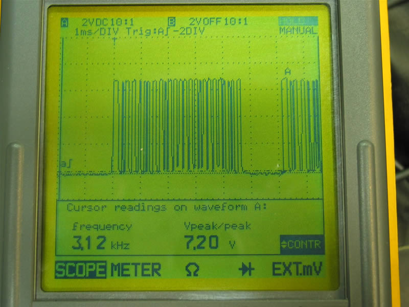
Here is an update. I'm learning waaaay too much about this data buss, more than I ever wanted to know! I sucked off the left component since it was the easiest to get too, and it was jumper between the buss and ground. Once removed the IPC data buss was released from ground. I check and both devices reads 0 ohm in both directions. I reinstalled the IPC in the car leaving the data buss disconnected for the rest of the car. I powered everything up and watched the data from the IPC on a scope. It read the same 6-7.5 VDC so I plugged the IPC onto the buss with all the other devices. Now everything seems to be working fine again! The "Reduced Engine Power" message is gone and I can once again read the codes with the DIC. After getting the component off I examined it better and found another number which I first thought was the date code, but the number is 5997 and it appears it may be a 1N5997 7.5V 500mW Zener Diode. This would make since being the buss runs just under 7.5VDC. I still don't understand the placement of these in the circuit, it looks like they would short out the buss. But with the multi-layered circuit boards you really don't know where the circuit runs. Guess I will get me a couple diodes and see how they work.
BTW: For anyone wanting to know if for any reason the IPC is not communicating you will receive the "Reduced Engine Power" message. Once working I unplugged the IPC to see the result and within 3 seconds the REP message was displayed. Not sure why the IPC is involved with the engine power. Also the data buss sits at 0VDC most of the time and is pulled up anywhere between 6VDC and 7.5VDC depending on who is talking. This makes it very hard to measure anything on the buss without a scope. Here is a screen shot of data on the data buss.
I sucked off the left component since it was the easiest to get too, and it was jumper between the buss and ground. Once removed the IPC data buss was released from ground. I check and both devices reads 0 ohm in both directions. I reinstalled the IPC in the car leaving the data buss disconnected for the rest of the car. I powered everything up and watched the data from the IPC on a scope. It read the same 6-7.5 VDC so I plugged the IPC onto the buss with all the other devices. Now everything seems to be working fine again! The "Reduced Engine Power" message is gone and I can once again read the codes with the DIC. After getting the component off I examined it better and found another number which I first thought was the date code, but the number is 5997 and it appears it may be a 1N5997 7.5V 500mW Zener Diode. This would make since being the buss runs just under 7.5VDC. I still don't understand the placement of these in the circuit, it looks like they would short out the buss. But with the multi-layered circuit boards you really don't know where the circuit runs. Guess I will get me a couple diodes and see how they work.BTW: For anyone wanting to know if for any reason the IPC is not communicating you will receive the "Reduced Engine Power" message. Once working I unplugged the IPC to see the result and within 3 seconds the REP message was displayed. Not sure why the IPC is involved with the engine power. Also the data buss sits at 0VDC most of the time and is pulled up anywhere between 6VDC and 7.5VDC depending on who is talking. This makes it very hard to measure anything on the buss without a scope. Here is a screen shot of data on the data buss.