
ebcm connector pinout
 10-26-2005, 01:23 PM
#1
7th Gear

Thread Starter

Member Since: Aug 2005
Posts: 7
Likes: 0
Received 0 Likes
on
0 Posts
Does anyone have the pinout for the connector on the ebcm module for a 2001 corvette. I have been getting code 1214 and need to check continuity.
thanks
thanks
 10-26-2005, 04:45 PM
#2
Tech Contributor


Member Since: Dec 1999
Location: Anthony TX
Posts: 32,736
Received 2,181 Likes
on
1,584 Posts
CI 6,7,8,9,11 Vet
St. Jude Donor '08

Send me your e-mail address to bill327@msn.com and i will try to help you out. I am trying to put something together for a number of forum members on this very same subject!
BC
BC
10-27-2005, 01:54 AM
#3
Burning Brakes

Document ID# 672737
2001 Chevrolet Corvette
--------------------------------------------------------------------------------
Antilock Brake System Connector End Views
Electronic Brake Control Module (EBCM)
Connector Part Information
� C1 - 15318099
� 7-Way F Metri-Pack 480 Series (BLK)
� C2 - 15354984
� 29 Way F Micro-Pack 100 Series (NAT)
Pin
Wire Color
Circuit No.
Function
A
RED
1642
Battery Positive Voltage
B
BRN
641
Ignition 3 voltage
C
GRY
1787
Variable Effort Steering Actuator High Effort Control
D
WHT
345
Variable Effort Steering Actuator Low Effort Control
E
--
--
Not Used
F
BLK/WHT
1251
Ground
G
BLK
1250
Ground
1
--
--
Not Used
2
TAN/BLK
464
Delivered Torque Signal
3
LT GRN
1763
Steering Wheel Position Signal A
4
--
--
Not Used
5
LT GRN/BLK
1338
Lateral Accelerometer Input (JL4)
6
LT BLU
20
Stop lamp Supply Voltage
7
--
--
Not Used
8
RED
885
Left Rear Wheel Speed Sensor Low Reference
9
BRN
882
Right Rear Wheel Speed Sensor Signal
10
DK GRN
872
Right Front Wheel Speed Sensor Signal
11
LT BLU
830
Left Front Wheel Speed Sensor Signa
12
ORN/BLK
463
Requested Torque Signal
13
ORN/BLK
556
Low Reference
14-16
--
--
Not Used
17
BLK
2626
Brake Pressure Sensor Signal (JL4)
18
LT BLU
1764
Steering Wheel Position Signal B
19
DK BLU
716
Yaw Rate Sensor Signal (JL4)
20
--
--
Not Used
21
LT BLU
1122
ABS/TCS Class 2 Serial Data
22
BLK
884
Left Rear Wheel Speed Sensor Signal
23
WHT
883
Right Rear Wheel Speed Sensor Low Reference
24
TAN
833
Right Front Wheel Speed Sensor Low Reference
25
YEL
873
Left Front Wheel Speed Sensor Low Reference
26
--
--
Not Used
27
GRY
1056
Steering Wheel Position Sensor 5V Reference Voltage
28
LT BLU
2627
Steering Position Sensor Signal
29
--
--
Not Used
Brake Fluid Pressure Sensor
Connector Part Information
� 15324236
� 3-Way F Metri-Pack 150 Series (BLK)
Pin
Wire Color
Circuit No.
Function
1
ORN/BLK
556
Low Reference
2
BLK
2626
Brake Pressure Sensor Signal
3
GRY
1056
Steering Wheel Position Sensor 5V Reference Voltage
Lateral Accelerometer Sensor
Connector Part Information
� 12146121
� 3-Way F Metri-Pack 150 Series (BRN)
Pin
Wire Color
Circuit No.
Function
A
GRY
1056
Steering Wheel Position Sensor 5V Reference Voltage
B
LT GRN/BLK
1338
Lateral Accelerometer Signal
C
ORN/BLK
556
Low Reference
Yaw Rate Sensor
Connector Part Information
� 12064758
� 3-Way F 150 Metri-Pack Series (BLK)
Pin
Wire Color
Circuit No.
Function
A
GRY
1056
Steering Wheel Position Sensor 5V Reference Voltage
B
ORN/BLK
556
Low Reference
C
DK BLU
910
Yaw Rate Sensor Signal
Electronic Traction/Suspension Control Switch
Connector Part Information
� 12040953
� 6-Way F Micro-Pack 100 Series (BLK)
Pin
Wire Color
Circuit No.
Function
5
BLK
150
Ground
6
BRN/WHT
1571
Traction Control Switch Signal
7
PNK/BLK
1385
Selective Ride Control Switch Low Reference
8
TAN/WHT
1384
Selective Ride Control Switch Signal
9
BRN/WHT
1244
Instrument Panel Lamp Supply Voltage - 2
10
ORN
2840
Battery Positive Voltage
--------------------------------------------------------------------------------
Document ID# 672737
2001 Chevrolet Corvette
sorry kinda long....but i hope this helps
2001 Chevrolet Corvette
--------------------------------------------------------------------------------
Antilock Brake System Connector End Views
Electronic Brake Control Module (EBCM)
Connector Part Information
� C1 - 15318099
� 7-Way F Metri-Pack 480 Series (BLK)
� C2 - 15354984
� 29 Way F Micro-Pack 100 Series (NAT)
Pin
Wire Color
Circuit No.
Function
A
RED
1642
Battery Positive Voltage
B
BRN
641
Ignition 3 voltage
C
GRY
1787
Variable Effort Steering Actuator High Effort Control
D
WHT
345
Variable Effort Steering Actuator Low Effort Control
E
--
--
Not Used
F
BLK/WHT
1251
Ground
G
BLK
1250
Ground
1
--
--
Not Used
2
TAN/BLK
464
Delivered Torque Signal
3
LT GRN
1763
Steering Wheel Position Signal A
4
--
--
Not Used
5
LT GRN/BLK
1338
Lateral Accelerometer Input (JL4)
6
LT BLU
20
Stop lamp Supply Voltage
7
--
--
Not Used
8
RED
885
Left Rear Wheel Speed Sensor Low Reference
9
BRN
882
Right Rear Wheel Speed Sensor Signal
10
DK GRN
872
Right Front Wheel Speed Sensor Signal
11
LT BLU
830
Left Front Wheel Speed Sensor Signa
12
ORN/BLK
463
Requested Torque Signal
13
ORN/BLK
556
Low Reference
14-16
--
--
Not Used
17
BLK
2626
Brake Pressure Sensor Signal (JL4)
18
LT BLU
1764
Steering Wheel Position Signal B
19
DK BLU
716
Yaw Rate Sensor Signal (JL4)
20
--
--
Not Used
21
LT BLU
1122
ABS/TCS Class 2 Serial Data
22
BLK
884
Left Rear Wheel Speed Sensor Signal
23
WHT
883
Right Rear Wheel Speed Sensor Low Reference
24
TAN
833
Right Front Wheel Speed Sensor Low Reference
25
YEL
873
Left Front Wheel Speed Sensor Low Reference
26
--
--
Not Used
27
GRY
1056
Steering Wheel Position Sensor 5V Reference Voltage
28
LT BLU
2627
Steering Position Sensor Signal
29
--
--
Not Used
Brake Fluid Pressure Sensor
Connector Part Information
� 15324236
� 3-Way F Metri-Pack 150 Series (BLK)
Pin
Wire Color
Circuit No.
Function
1
ORN/BLK
556
Low Reference
2
BLK
2626
Brake Pressure Sensor Signal
3
GRY
1056
Steering Wheel Position Sensor 5V Reference Voltage
Lateral Accelerometer Sensor
Connector Part Information
� 12146121
� 3-Way F Metri-Pack 150 Series (BRN)
Pin
Wire Color
Circuit No.
Function
A
GRY
1056
Steering Wheel Position Sensor 5V Reference Voltage
B
LT GRN/BLK
1338
Lateral Accelerometer Signal
C
ORN/BLK
556
Low Reference
Yaw Rate Sensor
Connector Part Information
� 12064758
� 3-Way F 150 Metri-Pack Series (BLK)
Pin
Wire Color
Circuit No.
Function
A
GRY
1056
Steering Wheel Position Sensor 5V Reference Voltage
B
ORN/BLK
556
Low Reference
C
DK BLU
910
Yaw Rate Sensor Signal
Electronic Traction/Suspension Control Switch
Connector Part Information
� 12040953
� 6-Way F Micro-Pack 100 Series (BLK)
Pin
Wire Color
Circuit No.
Function
5
BLK
150
Ground
6
BRN/WHT
1571
Traction Control Switch Signal
7
PNK/BLK
1385
Selective Ride Control Switch Low Reference
8
TAN/WHT
1384
Selective Ride Control Switch Signal
9
BRN/WHT
1244
Instrument Panel Lamp Supply Voltage - 2
10
ORN
2840
Battery Positive Voltage
--------------------------------------------------------------------------------
Document ID# 672737
2001 Chevrolet Corvette
sorry kinda long....but i hope this helps
10-27-2005, 01:57 AM
#4
Burning Brakes
Document ID# 670663
2001 Chevrolet Corvette
--------------------------------------------------------------------------------
DTC C1214
Circuit Description
The system relay is energized when the ignition is ON. The system relay supplies voltage to the solenoid valves and the pump motor. This voltage is referred to as the system voltage.
The electronic brake control module (EBCM) controls each solenoid valve by grounding the solenoid.
The EBCM controls the pump motor by grounding the control circuit. The pump serves 2 purposes:
Transfers brake fluid from the brake calipers to the master cylinder reservoir during pressure decrease events.
Transfers brake fluid from the master cylinder reservoir to the brake calipers during pressure increase events.
Conditions for Running the DTC
The ignition voltage is greater than 10.5 volts.
The system relay is commanded ON.
Conditions for Setting the DTC
The system voltage is less than 8 volts for 0.23 seconds.
Action Taken When the DTC Sets
If equipped, the following actions occur:
� The EBCM disables the ABS/TCS/VSES for the duration of the ignition cycle.
� The DRP does not function optimally.
� The ABS indicator turns ON.
� The Traction Control and Active Handling indicator turns ON.
� The DIC displays the following messages:
- Service ABS
- Service Traction System
- Service Active Handling
Conditions for Clearing the DTC
The condition for the DTC is no longer present and the DTC is cleared with a scan tool.
The EBCM automatically clears the history DTC when a current DTC is not detected in 100 consecutive drive cycles.
Diagnostic Aids
The system relay is integral to the EBCM. The relay is not serviceable.
Test Description
The number below refers to the step number on the diagnostic table.
Determines whether the DTC is current.
Step
Action
Values
Yes
No
Schematic Reference: ABS Schematics
Connector End View Reference: ABS Connector End Views
1
Did you perform the ABS Diagnostic System Check?
--
Go to Step 2
Go to Diagnostic System Check - ABS
2
Install a scan tool.
Turn ON the ignition, with the engine OFF.
Use the scan tool in order to clear the DTCs.
With the scan tool, perform the Automated Test.
Does the DTC reset as a current DTC?
--
Go to Step 3
Go to Testing for Intermittent and Poor Connections in Wiring Systems
3
Disconnect the pump motor harness pigtail connector of the BPMV.
Measure the resistance between each pump motor control circuit and the housing of the BPMV at the pump motor harness pigtail connector of the BPMV.
Does the DMM display the specified value?
OL
Go to Step 5 if you read OL
Go to Step 4
4
Replace the EBCM and the BPMV. Refer to Electronic Brake Control Module (EBCM) Replacement and Brake Pressure Modulator Valve (BPMV) Replacement .
Did you complete the repair?
--
Go to Step 6
--
5
Replace the EBCM. Refer to Electronic Brake Control Module (EBCM) Replacement .
Did you complete the repair?
--
Go to Step 6
--
6
Use the scan tool in order to clear the DTCs.
With the scan tool, perform the Automated Test.
Does the DTC reset?
--
Go to Step 2
System OK
--------------------------------------------------------------------------------
Document ID# 670663
2001 Chevrolet Corvette
2001 Chevrolet Corvette
--------------------------------------------------------------------------------
DTC C1214
Circuit Description
The system relay is energized when the ignition is ON. The system relay supplies voltage to the solenoid valves and the pump motor. This voltage is referred to as the system voltage.
The electronic brake control module (EBCM) controls each solenoid valve by grounding the solenoid.
The EBCM controls the pump motor by grounding the control circuit. The pump serves 2 purposes:
Transfers brake fluid from the brake calipers to the master cylinder reservoir during pressure decrease events.
Transfers brake fluid from the master cylinder reservoir to the brake calipers during pressure increase events.
Conditions for Running the DTC
The ignition voltage is greater than 10.5 volts.
The system relay is commanded ON.
Conditions for Setting the DTC
The system voltage is less than 8 volts for 0.23 seconds.
Action Taken When the DTC Sets
If equipped, the following actions occur:
� The EBCM disables the ABS/TCS/VSES for the duration of the ignition cycle.
� The DRP does not function optimally.
� The ABS indicator turns ON.
� The Traction Control and Active Handling indicator turns ON.
� The DIC displays the following messages:
- Service ABS
- Service Traction System
- Service Active Handling
Conditions for Clearing the DTC
The condition for the DTC is no longer present and the DTC is cleared with a scan tool.
The EBCM automatically clears the history DTC when a current DTC is not detected in 100 consecutive drive cycles.
Diagnostic Aids
The system relay is integral to the EBCM. The relay is not serviceable.
Test Description
The number below refers to the step number on the diagnostic table.
Determines whether the DTC is current.
Step
Action
Values
Yes
No
Schematic Reference: ABS Schematics
Connector End View Reference: ABS Connector End Views
1
Did you perform the ABS Diagnostic System Check?
--
Go to Step 2
Go to Diagnostic System Check - ABS
2
Install a scan tool.
Turn ON the ignition, with the engine OFF.
Use the scan tool in order to clear the DTCs.
With the scan tool, perform the Automated Test.
Does the DTC reset as a current DTC?
--
Go to Step 3
Go to Testing for Intermittent and Poor Connections in Wiring Systems
3
Disconnect the pump motor harness pigtail connector of the BPMV.
Measure the resistance between each pump motor control circuit and the housing of the BPMV at the pump motor harness pigtail connector of the BPMV.
Does the DMM display the specified value?
OL
Go to Step 5 if you read OL
Go to Step 4
4
Replace the EBCM and the BPMV. Refer to Electronic Brake Control Module (EBCM) Replacement and Brake Pressure Modulator Valve (BPMV) Replacement .
Did you complete the repair?
--
Go to Step 6
--
5
Replace the EBCM. Refer to Electronic Brake Control Module (EBCM) Replacement .
Did you complete the repair?
--
Go to Step 6
--
6
Use the scan tool in order to clear the DTCs.
With the scan tool, perform the Automated Test.
Does the DTC reset?
--
Go to Step 2
System OK
--------------------------------------------------------------------------------
Document ID# 670663
2001 Chevrolet Corvette
10-27-2005, 02:08 AM
#5
Drifting


Bill, I'm a victim of this problem now too. I think you should start a sticky because it appears there's a lot of us all suffering with the same or related problems. I'm getting C1226 and C1243 codes on my '98 C5 MN6 front mounted EBCTM with the typical ABS, AH and TC idiot lights and error messages everyday now. I haven't started troubleshooting yet, but have discovered that I can simply turn the ignition key to the start position while driving and it resets everything restoring my EBTCM functions back to normal. It will not engage the starter while the engine is running when you turn the key to the start position. Let's keep working this issue and maybe we'll discover the root cause which will help hundreds of CF members not to mention possibly saving us all a lot of money. I am an engineer and would love to reverse engineer and do failure analysis on a few failed EBTCMs and see what the main failure mode is. This whole thing seems to be an intermittent problem and often comes back in time after doing things such as cleaning grounds, cleaning connector contacts, replacing wheel sensors, replacing EBTCMs, etc. I wonder if a power bleed of the system using the Tech II tool would yield any positive results? Keep up the good work. You've helped many folks on here and I'm sure we all appreciate your willingness to help.
Cheers
John

Cheers
John
10-27-2005, 04:45 PM
#7
Tech Contributor
Member Since: Dec 1999
Location: Anthony TX
Posts: 32,736
Received 2,181 Likes
on
1,584 Posts
CI 6,7,8,9,11 Vet
St. Jude Donor '08
I'm so pissed off with this EBTCM issue that I could just scream!!! I got GM to replace my module and they gave me a voucher towards a new GM car for the money that I spent! ( I wonder what that will go towards???  (((((07- C6 Z06!!!!!))))
The last night the wife called me and said that I have some EBTCM codes A G A I N !!!

 I will look them up tonight and see what is going on!
I went to my local DMV a few months ago to turn in some tags and they had a poster on the wall that caught my attention! It gave me a phone number and a web site that I can use to report vehicle safety related problems. Sooo,,, I am going to try that first. I'm also going to start a thread to find out how many forum members have had this issue and see if there is some way that we can get some assistance on this issue! I wonder if there are any forum laywers that can tell us what is involved in starting a class action law suit or something! The little bit that I have become involved in this issue, I have about 20+ people asking me for assistance!
For all of you that are having EBTCM problems , you need to know that there are about three- four different types of EBCM/EBTCM's out there and I believe that each year may be different/incompatable! I have a 98 service manual and an 02 service manual. I will compare the pin outs of each year and see if they jive! The 97,98,99's are most likely simular, 2000 may be an odd ball and 2001 and 2002 should be simular to each other. I can NOT comment on 03-04. So be careful when using information from year to year. The EBTCM's with AH are much different than the earlier cars without AH. The cars that dont have AH have EBCM (Electronic Brake Control Modules) vise EBTCM's. (Electronic Brake Traction Control Modules)
The ground wire at G-101 is CRITICAL for proper EBCM/EBTCM operation!!!!!! If that ground is not connected properly, is corroded or broken, it will cause the module to set codes or fail.
I have all of my pictures ready to up load to Photobucket and will revive the Important Electrical Information (long) post again and I also plan on posting some troubleshooting procedures for the EBCM/EBTCM issues.
Bill Curlee
(((((07- C6 Z06!!!!!)))) The last night the wife called me and said that I have some EBTCM codes A G A I N !!!
I will look them up tonight and see what is going on! I went to my local DMV a few months ago to turn in some tags and they had a poster on the wall that caught my attention! It gave me a phone number and a web site that I can use to report vehicle safety related problems.
Sooo,,, I am going to try that first. I'm also going to start a thread to find out how many forum members have had this issue and see if there is some way that we can get some assistance on this issue! I wonder if there are any forum laywers that can tell us what is involved in starting a class action law suit or something! The little bit that I have become involved in this issue, I have about 20+ people asking me for assistance! For all of you that are having EBTCM problems , you need to know that there are about three- four different types of EBCM/EBTCM's out there and I believe that each year may be different/incompatable! I have a 98 service manual and an 02 service manual. I will compare the pin outs of each year and see if they jive! The 97,98,99's are most likely simular, 2000 may be an odd ball and 2001 and 2002 should be simular to each other. I can NOT comment on 03-04. So be careful when using information from year to year. The EBTCM's with AH are much different than the earlier cars without AH. The cars that dont have AH have EBCM (Electronic Brake Control Modules) vise EBTCM's. (Electronic Brake Traction Control Modules)
The ground wire at G-101 is CRITICAL for proper EBCM/EBTCM operation!!!!!! If that ground is not connected properly, is corroded or broken, it will cause the module to set codes or fail.
I have all of my pictures ready to up load to Photobucket and will revive the Important Electrical Information (long) post again and I also plan on posting some troubleshooting procedures for the EBCM/EBTCM issues.
Bill Curlee

 I love this stuff.
 11-08-2005, 10:55 AM
#11
Instructor
Member Since: Jan 2005
Location: Port Richey Florida
Posts: 213
Likes: 0
Received 0 Likes
on
0 Posts
Bill,
THANK YOU FOR STARTING THIS!
I have the same codes just like everone else, and I think this is BS!
We need to see what we can get done as a group!
Count me in!, If you need me to do anything to help this cause I am in!
THANK YOU FOR STARTING THIS!
I have the same codes just like everone else, and I think this is BS!
We need to see what we can get done as a group!
Count me in!,
If you need me to do anything to help this cause I am in!
11-08-2005, 12:59 PM
#12
Instructor

Member Since: Feb 2003
Location: Houston TX
Posts: 214
Likes: 0
Received 0 Likes
on
0 Posts

Oh my gosh, you are a Godsend! I just had a cam installed at MTI and now the damn light comes on everyday. Those guys have been no help so far and I already changed the wire harness from the brake module. I have a STRONG feeling it is an electrical problem as the problem only now shows up everday. I don't have warranty and don't feel like plunking down 3,000 dollars!
Please help and keep up the good work! I owe you all dinner if you fix this!!!!
Please help and keep up the good work! I owe you all dinner if you fix this!!!!
11-08-2005, 08:13 PM
#13
Burning Brakes
Member Since: Jan 2005
Location: Frankfort Illinois
Posts: 843
Likes: 0
Received 0 Likes
on
0 Posts
Bill, Thanks for spearheading this important issue, I believe I'm one of the 20+ with this issue. Got an appt. 1 week from today at the dealership, at this point I think I'll just get an estimate, I don't trust em.
Thanks, Ken
Thanks, Ken
11-08-2005, 10:10 PM
#14
Tech Contributor
Member Since: Dec 1999
Location: Anthony TX
Posts: 32,736
Received 2,181 Likes
on
1,584 Posts
CI 6,7,8,9,11 Vet
St. Jude Donor '08
Well,,,,,,,,,We purchased a new C6 Z51 and in the deal, I got the dealer to take a look at my EBTCM problem! 
With the codes that I was having C1226 and knowing that the EBTCM was new and that all of the wheel hub speed sensors were functioing properly, the only thing that it could have been was a bad connection/s
I asked them to do a pin pull test on all of the connectors.
Here is what the culprit was! The wiring harness connector that comes from the main EBTCM harness and branches off to the right front wheel had a bad female connector pin! There is very little grip on the male pin when it is inserted (I hate when the female pin has no GRIP!) 
Pics:
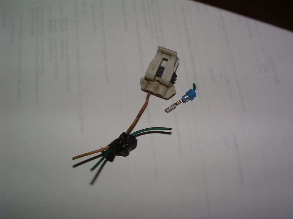
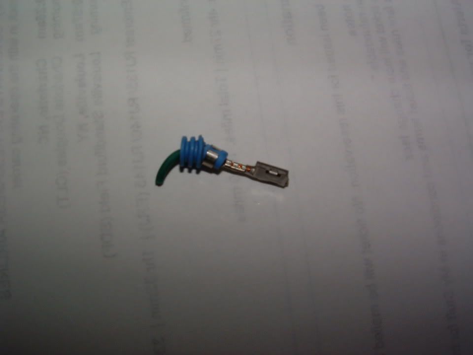
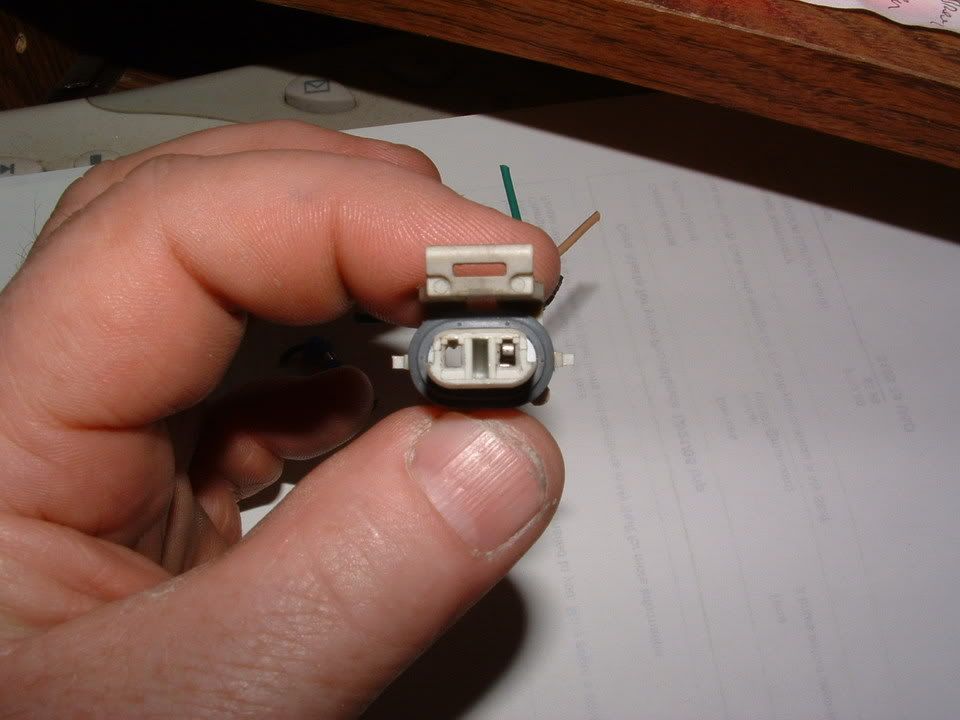
They crimped on two new female terminals and a new connector shell and it has not had a problem since.
Bill
With the codes that I was having C1226 and knowing that the EBTCM was new and that all of the wheel hub speed sensors were functioing properly, the only thing that it could have been was a bad connection/s
I asked them to do a pin pull test on all of the connectors.
Here is what the culprit was!
The wiring harness connector that comes from the main EBTCM harness and branches off to the right front wheel had a bad female connector pin! There is very little grip on the male pin when it is inserted (I hate when the female pin has no GRIP!) Pics:
They crimped on two new female terminals and a new connector shell and it has not had a problem since.
Bill
11-08-2005, 10:51 PM
#15
Drifting
I've recently noticed a discrepancy between my 98 shop manual and the error codes list that has been passed around.
Below is the error code list below we are all very familiar with:
28-TCS - Traction Control System
C1214 Sol Valve Relay Contact or Coil CKT Open
C1217 BPMV Pump Motor Relay Contact CKT Open
C1221 LF Wheel Speed Sensor Input Signal is 0
C1222 RF Wheel Speed Sensor Input Signal is 0
C1223 LR Wheel Speed Sensor Input Signal is 0
C1224 RR Wheel Speed Sensor Input Signal is 0
C1225 RF Excessive Wheel Speed Variation
C1226 LF Excessive Wheel Speed Variation
C1227 LR Excessive Wheel Speed Variation
I have a 1998 MN6 (front-mounted EBTCM) My '98 shop manual indicates C1226 is the RF excessive wheel speed variation. So is it possible that we may have been troubleshooting these problems on the wrong wheel? Anyway I have a conflict and need someone to straighten me out if I've missed something. Thanks!
John
Below is the error code list below we are all very familiar with:
28-TCS - Traction Control System
C1214 Sol Valve Relay Contact or Coil CKT Open
C1217 BPMV Pump Motor Relay Contact CKT Open
C1221 LF Wheel Speed Sensor Input Signal is 0
C1222 RF Wheel Speed Sensor Input Signal is 0
C1223 LR Wheel Speed Sensor Input Signal is 0
C1224 RR Wheel Speed Sensor Input Signal is 0
C1225 RF Excessive Wheel Speed Variation
C1226 LF Excessive Wheel Speed Variation
C1227 LR Excessive Wheel Speed Variation
I have a 1998 MN6 (front-mounted EBTCM) My '98 shop manual indicates C1226 is the RF excessive wheel speed variation. So is it possible that we may have been troubleshooting these problems on the wrong wheel?
Anyway I have a conflict and need someone to straighten me out if I've missed something. Thanks!John