When you click on links to various merchants on this site and make a purchase, this can result in this site earning a commission. Affiliate programs and affiliations include, but are not limited to, the eBay Partner Network.
If you look at the LTemple's first post to this thread, you can see his home page is altered from Joying's supplied home page, and that the temperature is displayed in degrees F.
In another post, he mentions that he downloaded Nova Launcher to enable his changes. I have been warming up to it, but I'm not there yet. https://play.google.com/store/apps/d...prime&hl=en_US
Thanks, have to go back and take a look at that! Haven't used C5 for a couple weeks. Hopefully this weekend I can get it squared away.
I had never heard of Joying, so I went with a known name; I found this Pioneer DMH-W4660NEX on Amazon and it came XM ready, with Bluetooth, HD radio, a back-up camera, built-in Alexa and a remote control. Works with both Apple CarPlay, Android Auto (i have 1 Android and 1 iPhone synced). Since I'm not mechanically inclined, I bit the bullet and paid for the installation. Having Ford Sync in my company car, it made the screen a must for my weekend touring car.
Is that the Metra console for a double din radio? I really like the look, just wish the finish would match.
Is that the Metra console for a double din radio? I really like the look, just wish the finish would match.
The Metra bezel is nice. I had purchased a new Metra bezel and Sony double din and was all set to go until I saw this Joying project. As has been discussed, the Joying install has its own unique challenges, but I enjoy that kind of thing (wiring, rooting, etc.) and decided to go in that direction. I'm just refinishing a stock bezel now that I'll use for the Joying install. Now I gotta sell the Metra bezel and Sony head unit....
But back to the Metra bezel. I've owned both VetteNuts and Metra Bezel's and I lean towards the Metra. Reason is the way it fits around the head unit. You can see in the photo above it has a nice clean fit around the head unit. The VetteNuts is not that well defined around the head unit. The bash that most have against Metra's bezel is the finish. Had I proceeded with my Metra install, I was going to add a texture finish to it with Sem's texture product. They both are nice products in their own way. Vettenuts keeps the OEM style cubby and cupholder doors, but not as well defined around the head unit. Some owners also have issues with the narrow horizontal strip separating the dd head unit and HVAC control panel. Metra has a nice head unit fit, but you lose cubby / cupholder doors and have the different texture.
Ok, so here's a live review of Car Launcher Pro. Don't laugh at my awesome video handling or speaking.....I'm a car guy, not a youtuber, lol. I just uploaded it so give it a minute if it's not live yet.
Ok, so here's a live review of Car Launcher Pro. Don't laugh at my awesome video handling or speaking.....I'm a car guy, not a youtuber, lol. I just uploaded it so give it a minute if it's not live yet.
So I just started addressing an extra AH/TCS panel for MetalMan's rotary encoder setup. You folks that bought his encoder may be interested in these pics.
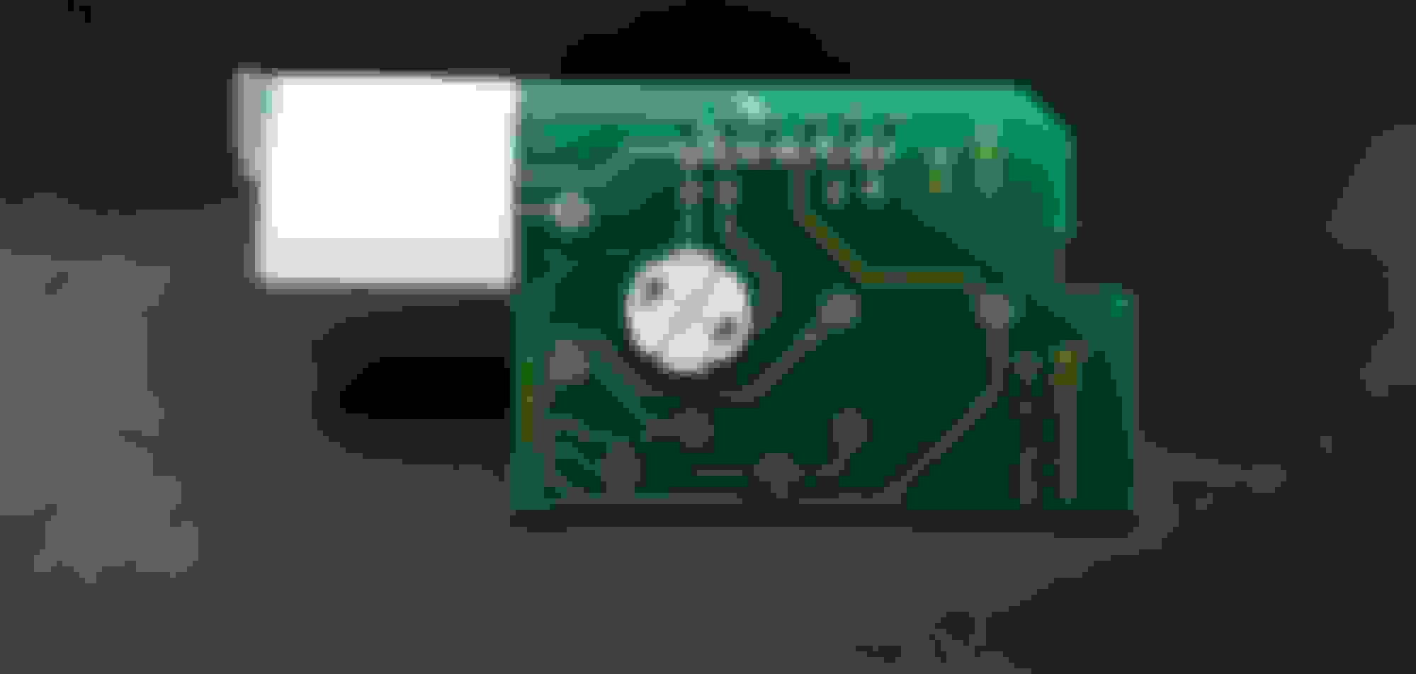
So here's the panel opened up. It simply clips together, no glue holding it together. The circuit board come out, GINGERLY. Pull it evenly, the pins are in pass throughs in the bottom of the lower panel.
Here you can see the approximate location of the Arduino and Rotary Encoder, and where the interference is.
Now, looking at the circuit board. The left side needs to go. But, the good news is that NO lighting or function will be lost on a NON-F45/F55 car. The worst case scenario would be a slightly dimmer light output due to losing the one bulb, but it should be a factor due to it's location (it's there for lighting the F45/55 Switch and Lettering on equipped cars). The one circuit that goes around that light on the left is terminated at the blank hole and not used that I can ascertain.
Moving to the inside of the switch panel, you can see the clear plastic light dispersing plastic. Half of it will need to be cut out, as well as the plastic stand. This is how the dispersing plastic is secured, but by what I can see, gluing it in place shouldn't pose any issues once it's cut.
I'll throw some more pics up after the fact, but by what I'm seeing here, I should be able to mount everything, get it back under the lower housing, and have the wire and USB both accessible. Will report back.
Then it was time to put the half diffuser back in place. Some 5 minute epoxy to the rescue. DO NOT put it around the edge near the switch. The entire switch button floats in the hole. I put epoxy on the bottom of the diffuser, and at the top right corner. Then I spread some around the base of the diffuser once it was tacky and in place. NOTE: On the bottom of the switch, there are two grey and black rubber stands. This is what supports the switch and gives it the positive feedback when you press it. They do fall right out, and just sit in place. Don't lose them, and ensure they go back in (one in the left recess, one in the right recess).
On the inside, left edge, there's a thin support ridge. I felt this was going to interfere with the Arduino so I used a dremel and drum sander to disappear it.
I made a 3/8 hole at the back.......easy access to the programming USB port now. I did this with the bottom plate ON the panel so I could clearance the lip on it (I went back after removing the bottom plate and used a sanding drum to further clearance it).
On the bottom panel, there was a hole you can see here on the right with some marks around it. I opened that up to 1/2" and ground the inside of the panel flat around the hole (there was about a 1/8" lip there). I had to elongate the hole towards the circuit board slightly just to not cause undue stress on the Arduino cable.
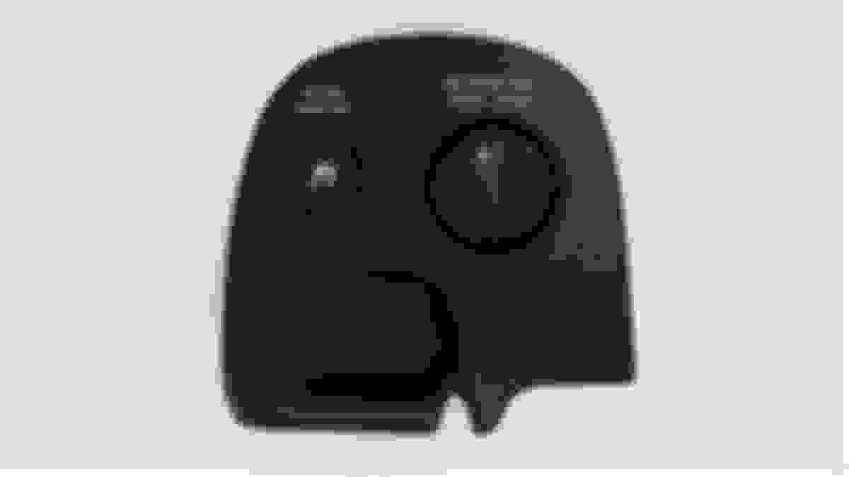
So this is what I ended up with. Looks like it was supposed to be there. Fits fine, and I have indeed verified that the Active Handling switch does indeed still light up with the vehicle lighting. Last thing I did before fully assembling was open a hole on the circular area of the bottom panel, so I've got access to the program button on the Arduino.
I am VERY happy with how this came out. The only thing is my car is a 99 and didn't have the Passenger Airbag light......so I'm not sure if I'm going to cut mine up or what at this point. May just use this one and deal with it.
@MetalMan2 Your packaging in how you assembled it was perfect to tuck into that panel. I'm actually considering finding a **** with a thumb recess on it, then opening the hole and figuring out a way to somewhat flush mount the ****. I think it would be slick if I could figure that out. Wouldn't be perfect due to the contour of the panel, but would be cool I think.
The bezel on Selective Ride cars already has the start for a flush mount. Could this be adapted for the volume control?
That was my plan but I wasn't able to locate a selective ride panel. Guy I use only had non selective ride ones (I don't want to spend $50+ to experiment on one, I got the one I used for $20).
Was just curious what's everyone's experience with the Joying in dash units? How are they holding up after a few months
of use and service? Pros/cons? Is everyone still happy with them? Looking to join the Joying club. Maybe.
Not sure if/when they'll be able to be rooted, but there's some good info in here on the differences between the old and new units (note, a lot of the Joying units appear to have the same "guts" but then they make different screen sizes for them.
I was more concerned about how they are holding up. How is the sound now that
you've lived with it for a while? Is the operation still smooth and user friendly? Those
are the things I want to know.
I was more concerned about how they are holding up. How is the sound now that
you've lived with it for a while? Is the operation still smooth and user friendly? Those
are the things I want to know.
Mine is doing well; sound quality and everything else is working great so far. A big thanks to MetalMan2 for the volume control device. I did put my own control **** on it however. Also, the setup on the screen is called "Car Widget" and the icons are "Evin Icon Pack".
I was more concerned about how they are holding up. How is the sound now that
you've lived with it for a while? Is the operation still smooth and user friendly? Those
are the things I want to know.
I wasn't responding to you (would have quoted you if so), but rather posting info for the group discussion. This thread isn't about just you.
Last edited by ArmchairArchitect; 10-02-2020 at 12:17 PM.
Anyone have trouble with Maps sizing properly on the resized (rooted) screen? I was showing the setup to my buddy but my maps for some reason didn't cooperate at all.

 09-28-2020, 10:06 AM