
removal of front turn signal lens, how?


 06-14-2010, 10:07 AM
#2
Race Director


Member Since: Jul 2008
Location: The Sunshine State
Posts: 17,010
Received 2,686 Likes
on
1,485 Posts
2022 C5 of the Year Finalist - Modified
2021 C5 of the Year Finalist - Modified
C7 of the Year - Modified Finalist 2021
Finalist 2020 C7 of the Year -- Modified
2020 C5 of the Year Finalist - Modified
C5 of Year Finalist (appearance mods) 2019
2018 C5 of Year Finalist

If you're referring to the actual corner light housings, you have two options...
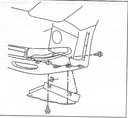
1) You can access the corners from underneath the car and removing the corner spoiler and back access panel in the wheel well.
or
2) If you are planning other mods, like HID lights, new fogs, etc., you can access the corner light housing from the top after you remove the stock lights. This is much easier than going in from underneath, however I would only recommend it if you're performing more than one mod. If it's just the corners, go in from underneath although it a little tougher on the back...
06-14-2010, 10:57 AM
#3


They are spring clipped into the fascia from the back side-if you push on them you'll feel the springs. You'll either have to get them from underneath or take the fascia off/loose (not a very tough job either).
06-14-2010, 10:58 AM
#4
Team Owner


check the C5 Tech DIY sticky..it is the first topic I even have pictures posted
06-14-2010, 11:03 AM
#5
Tech Contributor
Member Since: Dec 2003
Location: Horncastle Lincolnshire, England
Posts: 19,384
Likes: 0
Received 79 Likes
on
61 Posts
2023 C5 of the Year Finalist - Unmodified
pewter99s instructions are great
This might help too
Document ID# 655625
2002 Chevrolet Corvette
________________________________________
Park/Turn Signal/Side Marker Lamp Replacement
Removal Procedure
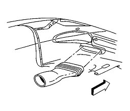
1. Raise and support the vehicle. Refer to Lifting and Jacking the Vehicle in General Information.
2. Remove the front fascia lower closeout panel.
3. Release the brake caliper cooling duct from the front fascia, and position the duct aside.
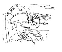
4. Remove the front turn signal lamp bracket retaining spring from the lamp bracket.
5. Remove the lamp bracket retaining spring from the front fascia.
6. Remove the front turn signal lamp bracket retaining screws.
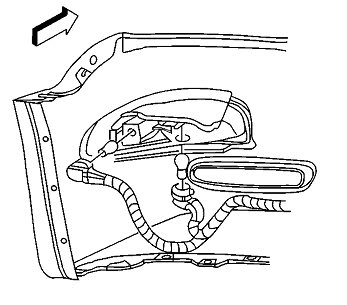
7. Disconnect the sockets from the lamp.
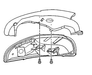
8. Remove the lamp, with the bracket, from the vehicle.
9. Remove the lamp to bracket retaining screws.
10. Remove the lamp from the bracket.
Installation Procedure
1. Install the front park/turn signal and sidemarker lamp into position on the front turn signal lamp bracket.
Notice
Use the correct fastener in the correct location. Replacement fasteners must be the correct part number for that application. Fasteners requiring replacement or fasteners requiring the use of thread locking compound or sealant are identified in the service procedure. Do not use paints, lubricants, or corrosion inhibitors on fasteners or fastener joint surfaces unless specified. These coatings affect fastener torque and joint clamping force and may damage the fastener. Use the correct tightening sequence and specifications when installing fasteners in order to avoid damage to parts and systems.
2. Install the front park/turn signal and sidemarker lamp to bracket retaining screws.
Tighten
Tighten the front park/turn signal and sidemarker lamp to bracket retaining screws to 2 N�m (18 lb in).
3. Install the sockets to the lamp.
4. Install the lamp, with the bracket, to the front fascia.
5. Align the lamp to the opening in the front fascia and hold the lamp firmly in place against the fascia, while installing the front turn signal lamp bracket retaining screws.
Tighten
Tighten the front turn signal lamp bracket retaining screws to 3 N�m (27 lb in).
6. Install the lamp bracket retaining spring to the front fascia.
7. Install the front turn signal lamp bracket retaining spring to the lamp bracket.
8. Position the brake caliper cooling duct to the front fascia and press the duct toward the fascia to secure.
9. Install the front fascia lower closeout panel. Refer to Close Out Panel - Front Bumper Fascia Lower in Bumpers.
This might help too
Document ID# 655625
2002 Chevrolet Corvette
________________________________________
Park/Turn Signal/Side Marker Lamp Replacement
Removal Procedure
1. Raise and support the vehicle. Refer to Lifting and Jacking the Vehicle in General Information.
2. Remove the front fascia lower closeout panel.
3. Release the brake caliper cooling duct from the front fascia, and position the duct aside.
4. Remove the front turn signal lamp bracket retaining spring from the lamp bracket.
5. Remove the lamp bracket retaining spring from the front fascia.
6. Remove the front turn signal lamp bracket retaining screws.
7. Disconnect the sockets from the lamp.
8. Remove the lamp, with the bracket, from the vehicle.
9. Remove the lamp to bracket retaining screws.
10. Remove the lamp from the bracket.
Installation Procedure
1. Install the front park/turn signal and sidemarker lamp into position on the front turn signal lamp bracket.
Notice
Use the correct fastener in the correct location. Replacement fasteners must be the correct part number for that application. Fasteners requiring replacement or fasteners requiring the use of thread locking compound or sealant are identified in the service procedure. Do not use paints, lubricants, or corrosion inhibitors on fasteners or fastener joint surfaces unless specified. These coatings affect fastener torque and joint clamping force and may damage the fastener. Use the correct tightening sequence and specifications when installing fasteners in order to avoid damage to parts and systems.
2. Install the front park/turn signal and sidemarker lamp to bracket retaining screws.
Tighten
Tighten the front park/turn signal and sidemarker lamp to bracket retaining screws to 2 N�m (18 lb in).
3. Install the sockets to the lamp.
4. Install the lamp, with the bracket, to the front fascia.
5. Align the lamp to the opening in the front fascia and hold the lamp firmly in place against the fascia, while installing the front turn signal lamp bracket retaining screws.
Tighten
Tighten the front turn signal lamp bracket retaining screws to 3 N�m (27 lb in).
6. Install the lamp bracket retaining spring to the front fascia.
7. Install the front turn signal lamp bracket retaining spring to the lamp bracket.
8. Position the brake caliper cooling duct to the front fascia and press the duct toward the fascia to secure.
9. Install the front fascia lower closeout panel. Refer to Close Out Panel - Front Bumper Fascia Lower in Bumpers.
The following users liked this post:
FreedomFighter (09-13-2016)
06-14-2010, 11:36 AM
#6
Race Director
Actually theere is only 1 spring and why it's even on it I have no clue. The 2 screws you take out are either 7mm or 8mm I forgot. I've take mine out about 4 times now for light upgrades.
06-14-2010, 11:47 AM
#7
Race Director
Member Since: Jul 2008
Location: The Sunshine State
Posts: 17,010
Received 2,686 Likes
on
1,485 Posts
2022 C5 of the Year Finalist - Modified
2021 C5 of the Year Finalist - Modified
C7 of the Year - Modified Finalist 2021
Finalist 2020 C7 of the Year -- Modified
2020 C5 of the Year Finalist - Modified
C5 of Year Finalist (appearance mods) 2019
2018 C5 of Year Finalist
 06-14-2010, 11:55 AM
#8
Race Director
 .
06-14-2010, 01:48 PM
.
06-14-2010, 01:48 PM
#9
Team Owner
