
Quick C5 Jacking Question
 11-07-2008, 03:37 PM
#1
Burning Brakes

Thread Starter

I've read a lot of posts about raising the C5. Is this an acceptable way to raise & support a C5?
1. Raise the front utilizing the proper jacking points.
2. Lower front on jack stands on front jacking pucks.
3. Raise the rear utilizing the proper jacking points.
4. Lower rear on jack stands on rear jacking pucks?
Do jack stands work beneath jacking pucks?
1. Raise the front utilizing the proper jacking points.
2. Lower front on jack stands on front jacking pucks.
3. Raise the rear utilizing the proper jacking points.
4. Lower rear on jack stands on rear jacking pucks?
Do jack stands work beneath jacking pucks?
 11-07-2008, 04:53 PM
#2
Drifting

Hi There:
You can do that but, you have all the weight resting on a 3" puck.Also doesn't leave much room for error when you lower on to puck. I prefer to use 2x6s & cover both sides of the frame. Much safer & no worries about damage to the under carriage.I use the pucks to raise the car and lower onto the stands.Sometimes I use the brute race ramps.Depends on the mood i guess.
robsc501
11-07-2008, 05:00 PM
#3
Burning Brakes
Thread Starter
You can do that but, you have all the weight resting on a 3" puck.Also doesn't leave much room for error when you lower on to puck. I prefer to use 2x6s & cover both sides of the frame. Much safer & no worries about damage to the under carriage.I use the pucks to raise the car and lower onto the stands
11-07-2008, 05:09 PM
#4
Tech Contributor
Member Since: Dec 2003
Location: Horncastle Lincolnshire, England
Posts: 19,384
Likes: 0
Received 79 Likes
on
61 Posts
2023 C5 of the Year Finalist - Unmodified

This is about all I know on the topic:
http://forums.corvetteforum.com/show...1&forum_id=103
Courtesy theadmiral94
Here's a diagram of the jacking points:
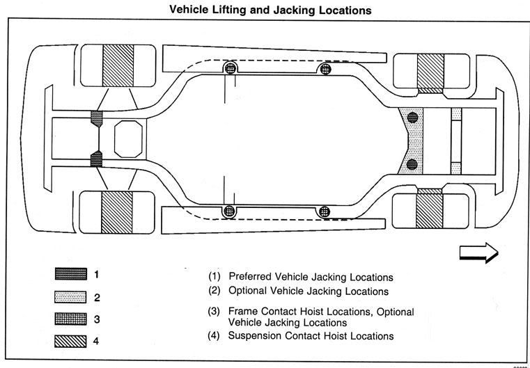
In Other Words -- how to lift and support your C5 per the GM Manual
This article will translate and document the GM Manual’s procedures for lifting and supporting a C5 (based on a 2000) and clearly define the distinction between a ‘hydraulic jack’ and where it can be placed -- versus -- ‘jack stands’ and where they can be placed.
This is not to say other suggested procedures would not work without damage.
However, after struggling through so many different suggested procedures and the manual, I decided to put this together to help the next 'new to them' owner of a C5.
The goal of this write-up is to accurately convey the GM Manual’s information so anyone can determine if a suggested procedure deviates from GM recommendations.
This information is taken from GM’s 2000 Service Manual, Volume 1 of 3, General Information, pages 0-33.
I should also credit two other websites for their information, upon which some of this article is based :
The Idaho Corvette Page and Z06vette.com
First, to identify some large differences between many suggested procedures and what the GM’s manual recommends. The GM Manual states or implies:
1. ‘Jack Stands’ should NOT be placed under the ‘frame rails’ (regardless of whether ‘hockey pucks’ are used or not).
2. A ‘hydraulic jack’ should NOT be placed directly under the CENTER of the ‘OPTIONAL’ front cross-member. The ‘Optional’ Front cross-member is FORWARD of the front fiberglass transverse spring and is the ‘optional’ front location for a ‘hydraulic jack’. By contrast, the ‘PREFERRED’ front location is to the REAR of the fiberglass transverse spring, immediately forward of the oil pan. This 'PREFERRED' cross-member can have a 'hydraulic Jack' placed directly under the center, however, doing so will most likely contact and may damage the oil pan/oil drain plug, so it is NOT advisable either.
3. A ‘hydraulic jack’ should NOT be placed directly under the CENTER of the rear cross-member to raise the rear of the car.
4. ‘Hockey Pucks’ should NOT be used at the FRONT Frame Rail location when lifting the car with a ‘service lift’. The presumably larger flat rectangular ‘service lift’ ‘pad’ is to be placed with its long side parallel with and at or immediately forward of the front ‘hockey puck’ AREA (note: this also assures a slightly higher rear end for proper oil draining from the oil pan).
Now on to what can be done.
First of all, here is the Service Manual’s vehicle diagram of the “Vehicle Lifting and Jacking Locations” (note: Jacking is NOT ‘Jack Stands’):
personal home page Lifting & Jacking Locations
The Service Manual has 3 sections within the ‘Lifting and Jacking the Vehicle section’. These sections can be easily switched and thereby confusing.
The FIRST SECTION is ‘Vehicle Lifting – Frame Contact Hoist’ (i.e. a ‘service lift’). This section clarifies the use of the ‘hockey pucks’ (special part # J43625) ONLY for the REAR, to be installed in the ‘rear frame rail shipping slots’. The presumably larger flat rectangular ‘service lift’ ‘pad’ is to be placed with its long side parallel with and at or immediately forward of the front ‘hockey puck’ AREA (without a ‘hockey puck’) AND not touching the body panels.
The SECOND SECTION ‘Vehicle Jacking’ (‘Hydraulic Jack’, not to be confused with ‘Jack Stands’ or a ‘service lift’) implies the use of ‘hockey pucks’ front and rear by specifying the use of “2 � inch or smaller diameter lifting pads when ‘jacking’ the car via the ‘frame rails’.
For the FRONT, this ‘Vehicle Jacking’ section continues to specify the ‘Preferred’ Front Suspension cross-member as the one behind the fiberglass transverse spring, immediately forward of the oil pan. This cross-member can be lifted anywhere along its width (center to 13” off-center), with the preferred location at the outer 7 � inches (and in the middle of that outer 7 � inches). Note, the usage of the ‘Preferred’ cross-member may make oil changes difficult as the cross member is more narrow at the center where it comes very close to the oil drain plug.
Further specified in this ‘Vehicle Jacking’ section is that the Front ‘Optional’ front cross-member should only be lifted at the outer 5 � inches of the overall 26 inch cross-member’s length and NOT in the center (when you look at the cross-member, you will understand why).
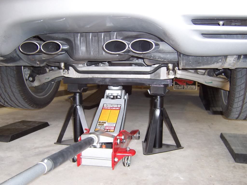
For the REAR, Similarly specified is that a ‘hydraulic Jack’ should NOT be placed in the center, it should only be placed at the outer and rearward sweeping 5 � inches (of the overall 26 inch length cross-member) (again, when you look at the cross-member and how it supports the body, you will understand why).
The THIRD SECTION ‘Supporting the Vehicle with Jack Stands’ first notes “Important: Do not place jack stands under the frame rails”.
It further specifies that ‘Jack Stands’ should only be placed under the outer areas of the three previously mentioned cross-members. Also, a ‘block or pad’ should be placed between the jack stands and the vehicle. Lastly, make sure the ‘jack stands’ ‘block or pad’ span at least 2 cross-member ribs (i.e. side to side thin aluminum ridge).
Some Personal notes/thoughts:
The cast aluminum cross-members should only be lifted with specially constructed wood ‘pads’ to prevent damage and possible cracking.
The car’s underbody is very low. There is only approximately 3� inches clearance below the front air dam, and only about 5 inches below most of the underbody, cross-members and side rails.
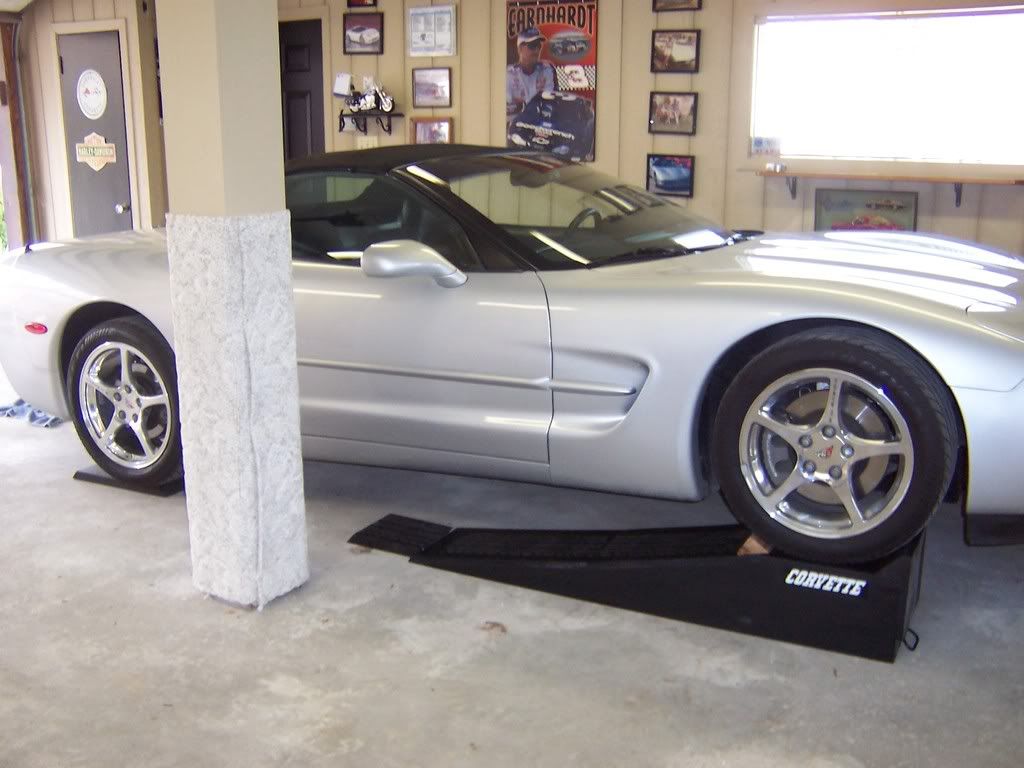
This low clearance creates a requirement for front and rear drive-on ramps with a minimum of 3” of lift to gain clearance to the cross-members for ‘jacking’ with specially constructed wood ‘pads’ and a low-profile hydraulic jack (e.g. #0950240 from Sears with 3�” to 18�” lifting range). Always first lift the front, otherwise there will not be enough clearance to do so after lifting the rear.
Now on to what you can make out of wood to comply with the GM Service Manual.
Here's a link to pictures of the home-made items:
Wood Ramps and Hydraulic Lifting Pads
Home Made Wood Ramps:
� Two 12 foot 2” x 12”
� One 8 foot 2” x 3”
� One box of #10 x 3” wood screws
Front: cut off 1’ from the worse end of the first 2” x 12” and set aside. Then cut two 3 �’ and two 2’ sections.
Rear: cut off 1’ from both ends of the other 2” x 12”, then cut two 3’ and two 2’ sections.
Both: cut eight 12” lengths for stop-blocks from the 2” x 3”. Four are for placing behind the tires after driving onto the ramps.
Cut a 30 degree angle on one end of each of the ten 2” x 12” sections. This can be done with a table-saw set at 30 degrees and each board held vertical (standing up) while passing between the guide and another guide/piece of wood (I used the first 1’ section set aside, clamped to the table).
Otherwise, if you only have a hand-held electric circular saw (which cannot cut the proper 30 degree angle on a vertical end as when set flat on the board, its 30 degree setting will actually cut a 60 degree ramp instead), then instead just cut a 45 degree angle on one end of each of the ten 2” x 12” sections.
Assemble front ramps: 12” 2”x3” stop-block on square end of 2’ 2”x12” on top of 3 �’ 2” x 12”. Pre-drill and screw together (2 screws for stop-block, 4 screws for 2’ to 3�‘).
Assemble rear ramps: 12” 2”x3” stop-block on square end of 2’ 2”x12” on top of 3’ 2” x 12”. Pre-drill and screw together. The two additional 1’ 2” x 12” sections are for placing under the tires after jacking to elevate the rear for proper oil draining. However, there may not be sufficient clearance to driver all the way off of the 3 levels, so you could roll off the 3rd level, then remove the 3rd level board before continuing down off the rest of the rear ramps.
Usage: Place the FRONT ramps with the stop block where you want the front tires to end up. Pull car just up to the ramp incline. Push the ramps up against the front tires and align the front ramps. Place the REAR ramps 6” in front of the rear tires and align (I use a 6” piece of wood as a spacer against the tire). Back car up without hitting any front mud flaps on rear ramps and accelerate smoothly. The car should hit the front ramp’s 1st level, then the rear ramp’s 1st level, then front and rear ramp’s 2nd levels almost simultaneously. Be sure the car is against the stop-blocks and set parking brake. Then set the four additional stop blocks behind each tire.
NOTE: The front ramps are only 3 �‘ long to be clear of the ‘hockey puck’ area, in case it is needed for ‘hydraulic Jacking’. The rear ramps are only 3’ and set 6” forward of the rear tire to prevent hitting both ramps at the same time thereby reducing the chance of their movement and insufficient speed to achieve making the 2nd level of both ramps.
Home Made Wood Hydraulic Jack Lifting Pads
Here's a link to pictures of the home-made items:
Wood Ramps and Hydraulic Lifting Pads
� One 8 foot 2” x 6”
� One 8 foot 2” x 8”
� #10 3 inch wood screws
For FRONT ‘Optional’ cross-member: cut two 6” sections, and one 26” section from the 2” x 6”. Assemble each 6” section on top, flush with the ends and parallel with the 26” section. Pre-drill and screw together.
When used on the ‘Optional’ front cross-member (area forward of the fiberglass transverse leaf spring), center the wood (side to side and front to back) with the 6” sections on top against the cross-member and contacting both front and rear ‘RIB’ with the hydraulic jack centered underneath the 26” section. Pre-drill and screw together. This way lifting pressure will NOT be applied under the center of the cross-member, only the ends, as specified by the GM Manual.
For FRONT ‘Recommended’ cross-member: cut two 8” sections and one 26” section from the 2” x 8”. Assemble each 8” section on top, flush with the ends and parallel with the 26” section. Pre-drill and screw together.
When used on the ‘Recommended’ front cross-member (area behind the fiberglass transverse leaf spring and immediately forward of the oil pan), center the wood (side to side and front to back) with the 8” sections on top against the cross-member and contacting both front and rear ‘RIB’, with the hydraulic jack centered underneath the 26” section. This way lifting pressure will NOT be applied to the middle of the cross-member where the wood would overlap the oil pan and oil drain plug. This could also allow still doing the oil change while the wood is in place.
‘Jack Stands’ should only be used with these wood lifting pads, placed underneath the ends of the 26” section on either side of the hydraulic jack (‘Jack Stands’ should NOT be placed under the ‘hockey pucks’ on the frame rails).
For REAR cross-member: Cut two 10” sections and one 26” section from the 2” x 6”. Assemble each 10” section on top, at each end, but perpendicular to the 26” section, somewhat centered, except that 3” should extending rearward of the 26” section, and 1�“ should extending forward of the 26” section (looks like a ‘U’ with downward legs when assembled).
When used on REAR cross-member, center (side to side and front to back) the 26” section on the center of the rear cross-member directly under both ‘ribs’, with the 10” sections upward and against the cross member and pointing rearward so as to ALSO be underneath the cross-member ends which are more rearward (tie-rod ends). Place the hydraulic jack centered underneath the middle of the 26” section. This way lifting pressure will NOT be applied under the center of the cross-member, only the ends, as specified by the GM Service Manual.
‘Jack Stands’ should only be used with this wood lifting pad, placed underneath the ends of the 26” section and centered below the 10” sections on both sides of the hydraulic jack (‘Jack Stands’ should NOT be placed under the ‘hockey pucks’ on the frame rails).
Set the rear ‘jack stands’ one (1) notch higher than the front ‘jack stands’ for a level car.
Set the rear ‘jack stands’ two (2) notches higher than the front ‘jack stands’ when performing an oil change (will level/slightly tip the oil pan to fully drain the oil).
__________________
http://forums.corvetteforum.com/show...1&forum_id=103
Courtesy theadmiral94
Here's a diagram of the jacking points:
In Other Words -- how to lift and support your C5 per the GM Manual
This article will translate and document the GM Manual’s procedures for lifting and supporting a C5 (based on a 2000) and clearly define the distinction between a ‘hydraulic jack’ and where it can be placed -- versus -- ‘jack stands’ and where they can be placed.
This is not to say other suggested procedures would not work without damage.
However, after struggling through so many different suggested procedures and the manual, I decided to put this together to help the next 'new to them' owner of a C5.
The goal of this write-up is to accurately convey the GM Manual’s information so anyone can determine if a suggested procedure deviates from GM recommendations.
This information is taken from GM’s 2000 Service Manual, Volume 1 of 3, General Information, pages 0-33.
I should also credit two other websites for their information, upon which some of this article is based :
The Idaho Corvette Page and Z06vette.com
First, to identify some large differences between many suggested procedures and what the GM’s manual recommends. The GM Manual states or implies:
1. ‘Jack Stands’ should NOT be placed under the ‘frame rails’ (regardless of whether ‘hockey pucks’ are used or not).
2. A ‘hydraulic jack’ should NOT be placed directly under the CENTER of the ‘OPTIONAL’ front cross-member. The ‘Optional’ Front cross-member is FORWARD of the front fiberglass transverse spring and is the ‘optional’ front location for a ‘hydraulic jack’. By contrast, the ‘PREFERRED’ front location is to the REAR of the fiberglass transverse spring, immediately forward of the oil pan. This 'PREFERRED' cross-member can have a 'hydraulic Jack' placed directly under the center, however, doing so will most likely contact and may damage the oil pan/oil drain plug, so it is NOT advisable either.
3. A ‘hydraulic jack’ should NOT be placed directly under the CENTER of the rear cross-member to raise the rear of the car.
4. ‘Hockey Pucks’ should NOT be used at the FRONT Frame Rail location when lifting the car with a ‘service lift’. The presumably larger flat rectangular ‘service lift’ ‘pad’ is to be placed with its long side parallel with and at or immediately forward of the front ‘hockey puck’ AREA (note: this also assures a slightly higher rear end for proper oil draining from the oil pan).
Now on to what can be done.
First of all, here is the Service Manual’s vehicle diagram of the “Vehicle Lifting and Jacking Locations” (note: Jacking is NOT ‘Jack Stands’):
personal home page Lifting & Jacking Locations
The Service Manual has 3 sections within the ‘Lifting and Jacking the Vehicle section’. These sections can be easily switched and thereby confusing.
The FIRST SECTION is ‘Vehicle Lifting – Frame Contact Hoist’ (i.e. a ‘service lift’). This section clarifies the use of the ‘hockey pucks’ (special part # J43625) ONLY for the REAR, to be installed in the ‘rear frame rail shipping slots’. The presumably larger flat rectangular ‘service lift’ ‘pad’ is to be placed with its long side parallel with and at or immediately forward of the front ‘hockey puck’ AREA (without a ‘hockey puck’) AND not touching the body panels.
The SECOND SECTION ‘Vehicle Jacking’ (‘Hydraulic Jack’, not to be confused with ‘Jack Stands’ or a ‘service lift’) implies the use of ‘hockey pucks’ front and rear by specifying the use of “2 � inch or smaller diameter lifting pads when ‘jacking’ the car via the ‘frame rails’.
For the FRONT, this ‘Vehicle Jacking’ section continues to specify the ‘Preferred’ Front Suspension cross-member as the one behind the fiberglass transverse spring, immediately forward of the oil pan. This cross-member can be lifted anywhere along its width (center to 13” off-center), with the preferred location at the outer 7 � inches (and in the middle of that outer 7 � inches). Note, the usage of the ‘Preferred’ cross-member may make oil changes difficult as the cross member is more narrow at the center where it comes very close to the oil drain plug.
Further specified in this ‘Vehicle Jacking’ section is that the Front ‘Optional’ front cross-member should only be lifted at the outer 5 � inches of the overall 26 inch cross-member’s length and NOT in the center (when you look at the cross-member, you will understand why).
For the REAR, Similarly specified is that a ‘hydraulic Jack’ should NOT be placed in the center, it should only be placed at the outer and rearward sweeping 5 � inches (of the overall 26 inch length cross-member) (again, when you look at the cross-member and how it supports the body, you will understand why).
The THIRD SECTION ‘Supporting the Vehicle with Jack Stands’ first notes “Important: Do not place jack stands under the frame rails”.
It further specifies that ‘Jack Stands’ should only be placed under the outer areas of the three previously mentioned cross-members. Also, a ‘block or pad’ should be placed between the jack stands and the vehicle. Lastly, make sure the ‘jack stands’ ‘block or pad’ span at least 2 cross-member ribs (i.e. side to side thin aluminum ridge).
Some Personal notes/thoughts:
The cast aluminum cross-members should only be lifted with specially constructed wood ‘pads’ to prevent damage and possible cracking.
The car’s underbody is very low. There is only approximately 3� inches clearance below the front air dam, and only about 5 inches below most of the underbody, cross-members and side rails.
This low clearance creates a requirement for front and rear drive-on ramps with a minimum of 3” of lift to gain clearance to the cross-members for ‘jacking’ with specially constructed wood ‘pads’ and a low-profile hydraulic jack (e.g. #0950240 from Sears with 3�” to 18�” lifting range). Always first lift the front, otherwise there will not be enough clearance to do so after lifting the rear.
Now on to what you can make out of wood to comply with the GM Service Manual.
Here's a link to pictures of the home-made items:
Wood Ramps and Hydraulic Lifting Pads
Home Made Wood Ramps:
� Two 12 foot 2” x 12”
� One 8 foot 2” x 3”
� One box of #10 x 3” wood screws
Front: cut off 1’ from the worse end of the first 2” x 12” and set aside. Then cut two 3 �’ and two 2’ sections.
Rear: cut off 1’ from both ends of the other 2” x 12”, then cut two 3’ and two 2’ sections.
Both: cut eight 12” lengths for stop-blocks from the 2” x 3”. Four are for placing behind the tires after driving onto the ramps.
Cut a 30 degree angle on one end of each of the ten 2” x 12” sections. This can be done with a table-saw set at 30 degrees and each board held vertical (standing up) while passing between the guide and another guide/piece of wood (I used the first 1’ section set aside, clamped to the table).
Otherwise, if you only have a hand-held electric circular saw (which cannot cut the proper 30 degree angle on a vertical end as when set flat on the board, its 30 degree setting will actually cut a 60 degree ramp instead), then instead just cut a 45 degree angle on one end of each of the ten 2” x 12” sections.
Assemble front ramps: 12” 2”x3” stop-block on square end of 2’ 2”x12” on top of 3 �’ 2” x 12”. Pre-drill and screw together (2 screws for stop-block, 4 screws for 2’ to 3�‘).
Assemble rear ramps: 12” 2”x3” stop-block on square end of 2’ 2”x12” on top of 3’ 2” x 12”. Pre-drill and screw together. The two additional 1’ 2” x 12” sections are for placing under the tires after jacking to elevate the rear for proper oil draining. However, there may not be sufficient clearance to driver all the way off of the 3 levels, so you could roll off the 3rd level, then remove the 3rd level board before continuing down off the rest of the rear ramps.
Usage: Place the FRONT ramps with the stop block where you want the front tires to end up. Pull car just up to the ramp incline. Push the ramps up against the front tires and align the front ramps. Place the REAR ramps 6” in front of the rear tires and align (I use a 6” piece of wood as a spacer against the tire). Back car up without hitting any front mud flaps on rear ramps and accelerate smoothly. The car should hit the front ramp’s 1st level, then the rear ramp’s 1st level, then front and rear ramp’s 2nd levels almost simultaneously. Be sure the car is against the stop-blocks and set parking brake. Then set the four additional stop blocks behind each tire.
NOTE: The front ramps are only 3 �‘ long to be clear of the ‘hockey puck’ area, in case it is needed for ‘hydraulic Jacking’. The rear ramps are only 3’ and set 6” forward of the rear tire to prevent hitting both ramps at the same time thereby reducing the chance of their movement and insufficient speed to achieve making the 2nd level of both ramps.
Home Made Wood Hydraulic Jack Lifting Pads
Here's a link to pictures of the home-made items:
Wood Ramps and Hydraulic Lifting Pads
� One 8 foot 2” x 6”
� One 8 foot 2” x 8”
� #10 3 inch wood screws
For FRONT ‘Optional’ cross-member: cut two 6” sections, and one 26” section from the 2” x 6”. Assemble each 6” section on top, flush with the ends and parallel with the 26” section. Pre-drill and screw together.
When used on the ‘Optional’ front cross-member (area forward of the fiberglass transverse leaf spring), center the wood (side to side and front to back) with the 6” sections on top against the cross-member and contacting both front and rear ‘RIB’ with the hydraulic jack centered underneath the 26” section. Pre-drill and screw together. This way lifting pressure will NOT be applied under the center of the cross-member, only the ends, as specified by the GM Manual.
For FRONT ‘Recommended’ cross-member: cut two 8” sections and one 26” section from the 2” x 8”. Assemble each 8” section on top, flush with the ends and parallel with the 26” section. Pre-drill and screw together.
When used on the ‘Recommended’ front cross-member (area behind the fiberglass transverse leaf spring and immediately forward of the oil pan), center the wood (side to side and front to back) with the 8” sections on top against the cross-member and contacting both front and rear ‘RIB’, with the hydraulic jack centered underneath the 26” section. This way lifting pressure will NOT be applied to the middle of the cross-member where the wood would overlap the oil pan and oil drain plug. This could also allow still doing the oil change while the wood is in place.
‘Jack Stands’ should only be used with these wood lifting pads, placed underneath the ends of the 26” section on either side of the hydraulic jack (‘Jack Stands’ should NOT be placed under the ‘hockey pucks’ on the frame rails).
For REAR cross-member: Cut two 10” sections and one 26” section from the 2” x 6”. Assemble each 10” section on top, at each end, but perpendicular to the 26” section, somewhat centered, except that 3” should extending rearward of the 26” section, and 1�“ should extending forward of the 26” section (looks like a ‘U’ with downward legs when assembled).
When used on REAR cross-member, center (side to side and front to back) the 26” section on the center of the rear cross-member directly under both ‘ribs’, with the 10” sections upward and against the cross member and pointing rearward so as to ALSO be underneath the cross-member ends which are more rearward (tie-rod ends). Place the hydraulic jack centered underneath the middle of the 26” section. This way lifting pressure will NOT be applied under the center of the cross-member, only the ends, as specified by the GM Service Manual.
‘Jack Stands’ should only be used with this wood lifting pad, placed underneath the ends of the 26” section and centered below the 10” sections on both sides of the hydraulic jack (‘Jack Stands’ should NOT be placed under the ‘hockey pucks’ on the frame rails).
Set the rear ‘jack stands’ one (1) notch higher than the front ‘jack stands’ for a level car.
Set the rear ‘jack stands’ two (2) notches higher than the front ‘jack stands’ when performing an oil change (will level/slightly tip the oil pan to fully drain the oil).
__________________
Last edited by DeeGee; 11-07-2008 at 05:11 PM.
11-07-2008, 05:26 PM
#5
Instructor


Member Since: Mar 2008
Posts: 142
Likes: 0
Received 0 Likes
on
0 Posts
OK, I'll bite.
Why should you not place the jack stands under the "hockey pucs" if that is where the dealer will place the lift pads.
The only reasons I can think of is 1) movement of the car could cause it to rock off of the jack stands (this would also happen no matter where they were placed). 2) The rocking action of lifting up the car by one end and then the other end could cause the jack stands to tip.
11-07-2008, 07:27 PM
#6
Drifting
Hi geezel
Sorry I forgot to mention I use 2 floor jacks & a helper as to jack the car evenly using the pucks.Then the 2x6s on top of the j/stands.
I just think its a little unsafe to put j/stands under the puck. What do you think?
robsc501
Sorry I forgot to mention I use 2 floor jacks & a helper as to jack the car evenly using the pucks.Then the 2x6s on top of the j/stands.
I just think its a little unsafe to put j/stands under the puck. What do you think?
robsc501
 11-07-2008, 08:36 PM
#8
Pro

Member Since: Mar 2007
Location: Mission Viejo CA
Posts: 574
Likes: 0
Received 0 Likes
on
0 Posts

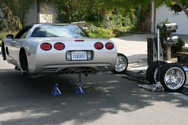
When going onto four jack stands here is the method I use. This will greatly reduce movement which can put pressure on the jack stands as you go up.
Make absolutely sure you are on flat ground!!
1. Drive it onto ramps to lift the front
2. Raise the rear and place it on jacks stands
3. Raise the front, place it on the jack stands and remove the ramps.
To lower repeat in reverse.
 savage1
Make absolutely sure you are on flat ground!!
1. Drive it onto ramps to lift the front
2. Raise the rear and place it on jacks stands
3. Raise the front, place it on the jack stands and remove the ramps.
To lower repeat in reverse.
savage1
11-07-2008, 11:19 PM
#11
Safety Car

12-01-2010, 01:31 PM
#12
Racer

Member Since: Jun 2002
Location: Lonoke Arkansas
Posts: 254
Likes: 0
Received 0 Likes
on
0 Posts
When going onto four jack stands here is the method I use. This will greatly reduce movement which can put pressure on the jack stands as you go up.
Make absolutely sure you are on flat ground!!
1. Drive it onto ramps to lift the front
2. Raise the rear and place it on jacks stands
3. Raise the front, place it on the jack stands and remove the ramps.
To lower repeat in reverse.
savage1
Make absolutely sure you are on flat ground!!
1. Drive it onto ramps to lift the front
2. Raise the rear and place it on jacks stands
3. Raise the front, place it on the jack stands and remove the ramps.
To lower repeat in reverse.
savage1
12-01-2010, 02:26 PM
#13

When going onto four jack stands here is the method I use. This will greatly reduce movement which can put pressure on the jack stands as you go up.
Make absolutely sure you are on flat ground!!
1. Drive it onto ramps to lift the front
2. Raise the rear and place it on jacks stands
3. Raise the front, place it on the jack stands and remove the ramps.
To lower repeat in reverse.
savage1
Make absolutely sure you are on flat ground!!
1. Drive it onto ramps to lift the front
2. Raise the rear and place it on jacks stands
3. Raise the front, place it on the jack stands and remove the ramps.
To lower repeat in reverse.
savage1Although I don't support the weight of the car on these I also like to chock up some stands on the rear rail lifting points just for extra insurance/peace of mind after I've lowered the rear onto stands under the cross member.
12-01-2010, 03:05 PM
#15
Melting Slicks

Member Since: Jun 2010
Location: Yorktown Virginia
Posts: 2,809
Likes: 0
Received 3 Likes
on
3 Posts
When going onto four jack stands here is the method I use. This will greatly reduce movement which can put pressure on the jack stands as you go up.
Make absolutely sure you are on flat ground!!
1. Drive it onto ramps to lift the front
2. Raise the rear and place it on jacks stands
3. Raise the front, place it on the jack stands and remove the ramps.
To lower repeat in reverse.
savage1
Make absolutely sure you are on flat ground!!
1. Drive it onto ramps to lift the front
2. Raise the rear and place it on jacks stands
3. Raise the front, place it on the jack stands and remove the ramps.
To lower repeat in reverse.
savage1
12-01-2010, 06:05 PM
#16
Melting Slicks
Member Since: Apr 2009
Location: Gastonia NC
Posts: 2,772
Likes: 0
Received 2 Likes
on
2 Posts
St. Jude Donor '10
I drive up on some 2x6s, put a 2x6 on top of your jack and lift (see DeeGee's post as to where). Set it down with the jack stands under the wood and your done. I found that I only need 1 2x6 under the wheels on the stock height with a low profile jack to get under it.

01-17-2014, 07:16 PM
#17
Instructor
Member Since: Aug 2011
Location: Te Kauwhata New Zealand
Posts: 200
Received 0 Likes
on
0 Posts
Just to ask, I prefer to make my own gear.
Can someone advise me what sizes I need to make them. I am thinking of 100(l)x75(w)x50(h).
To keep it simple I will not be making them round. Don't see this as being an issue.
From my reading on the pucks, they appear to only remove the risk of damaging the panels.
Thanks Kevin.
Can someone advise me what sizes I need to make them. I am thinking of 100(l)x75(w)x50(h).
To keep it simple I will not be making them round. Don't see this as being an issue.
From my reading on the pucks, they appear to only remove the risk of damaging the panels.
Thanks Kevin.