
LED Radio Install Guide... {Dial Up Warning}
 03-16-2005, 01:21 AM
#1
Le Mans Master

Thread Starter
Hey guys, I finally got the radio back in the car after 8 long hours of installing LED's in the stock radio. Let me say that it's not easy to do this and should not be done by anyone without prior soldering experience... With that said, I want to thank Stephen (EnglandGreen) for donating a radio to me! He even covered shipping ! Your a class act, thanks  !
!
Now before you get started, I'll say again that this is a major PITA (there you go Dave) but the results are worth it if you have the time (or enough money to bribe a friend to do it)! Make sure you read through the entire thread before starting on this project.
So here's the tools and supplies I used throughout the project:
#15 Torx screwdriver
7mm 1/4" socket
10mm 1/4" socket
Two flathead screwdrivers
A wood etching tool with a soldering tip (for the circuit board)
A soldering gun
Solder (just in case)
Liquid electrical flux
(10) 5mm blue LED's
(10) 470 ohm resistors
(1) 3mm blue LED (o resistor)
Dremel with Cutting and Sanding Tool
Side cutters
Needle-nose Pliers
Small Heat Shrink Tubing
and a 9V battery with ends to test the circuit board
(I might have forgot something here or there, sorry)
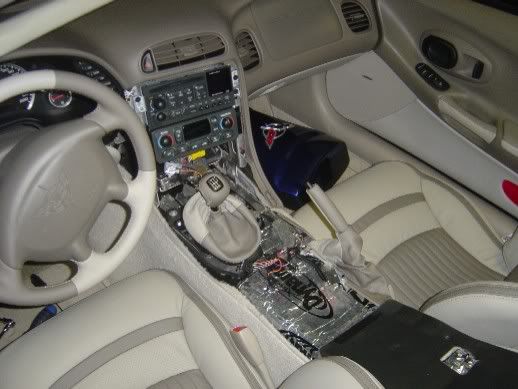
Now, the first thing you are going to have to get the radio out of the car. Do this first by pulling off the waterfall, which is attached with 4 #15 Torx screws (a least for us vert guys) .
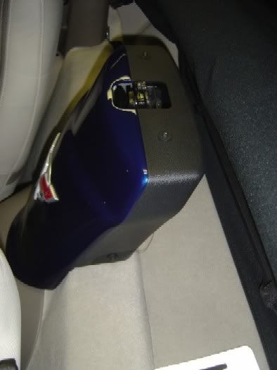
To remove the center console, open it up, pull up the two tabs in the back, and remove the two nuts with a 10mm socket.
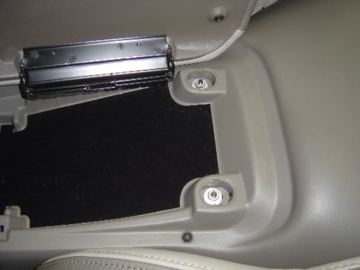
Pull up the A/H / SRC console with your fingertips or screwdriver wrapped in a towel. Detach the wires and remove those nuts too with a 10mm socket. Put the console in a safe place...
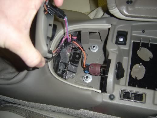
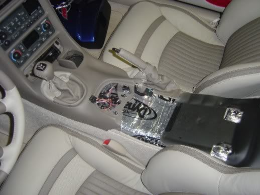
Now you have to remove the dash piece. There are three #15 torx screws holding this in place. Two are located in the ashtray area (one is behind the ashtray) and the third is located behind the little vent looking cover by the ignition (remove this with a small towel wrapped screwdriver from the bottom. With these removed and your MN6 in 2nd gear (1st for you A4 guys), remove the shifter boot (it just clicks in) and lift the cover up and out of the car. (There is a wire to the outlet in there so detach theat before removing the console).
!Now before you get started, I'll say again that this is a major PITA (there you go Dave) but the results are worth it if you have the time (or enough money to bribe a friend to do it)! Make sure you read through the entire thread before starting on this project.
So here's the tools and supplies I used throughout the project:
#15 Torx screwdriver
7mm 1/4" socket
10mm 1/4" socket
Two flathead screwdrivers
A wood etching tool with a soldering tip (for the circuit board)
A soldering gun
Solder (just in case)
Liquid electrical flux
(10) 5mm blue LED's
(10) 470 ohm resistors
(1) 3mm blue LED (o resistor)
Dremel with Cutting and Sanding Tool
Side cutters
Needle-nose Pliers
Small Heat Shrink Tubing
and a 9V battery with ends to test the circuit board
(I might have forgot something here or there, sorry)
Now, the first thing you are going to have to get the radio out of the car. Do this first by pulling off the waterfall, which is attached with 4 #15 Torx screws (a least for us vert guys) .
To remove the center console, open it up, pull up the two tabs in the back, and remove the two nuts with a 10mm socket.
Pull up the A/H / SRC console with your fingertips or screwdriver wrapped in a towel. Detach the wires and remove those nuts too with a 10mm socket. Put the console in a safe place...
Now you have to remove the dash piece. There are three #15 torx screws holding this in place. Two are located in the ashtray area (one is behind the ashtray) and the third is located behind the little vent looking cover by the ignition (remove this with a small towel wrapped screwdriver from the bottom. With these removed and your MN6 in 2nd gear (1st for you A4 guys), remove the shifter boot (it just clicks in) and lift the cover up and out of the car. (There is a wire to the outlet in there so detach theat before removing the console).
Last edited by CUlookin; 03-16-2005 at 11:29 AM.
 03-16-2005, 01:21 AM
#2
Le Mans Master
Thread Starter
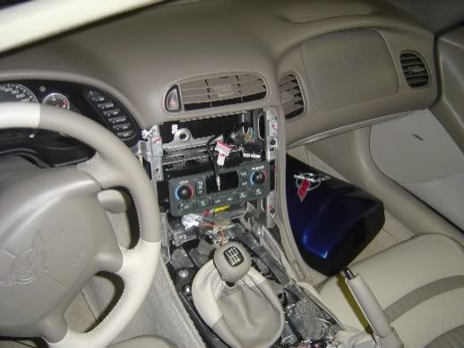
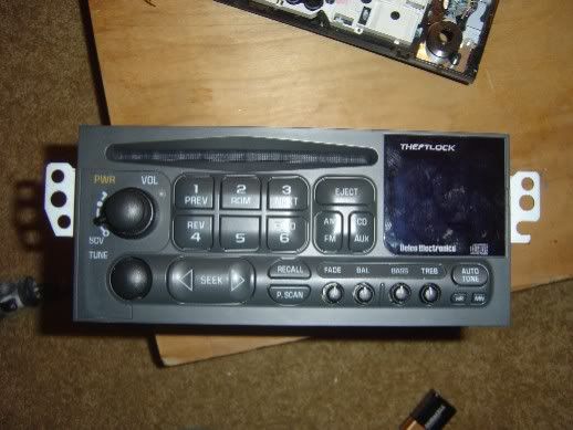
Now the radio is exposed. There are (2) 7mm screws holding this on. Remove them and pull the radio out so that the rear wires are exposed. Unclick the 4 wires in the back. The 12disc CD changer cord pulls directly out the back if so equipped.
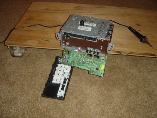
Now let the fun begin! To remove the cover on the radio, first pull out the Tune **** (it comes right off). Next, there are 8 taps located around the sides protruding from the face. Gently pry these up enough to release the face. Note: they face and circuit board are attached with wires!! Don't pull too hard.
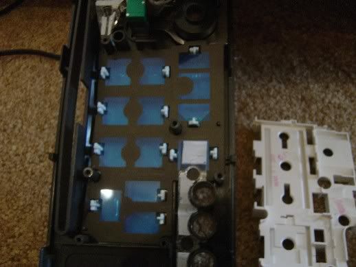
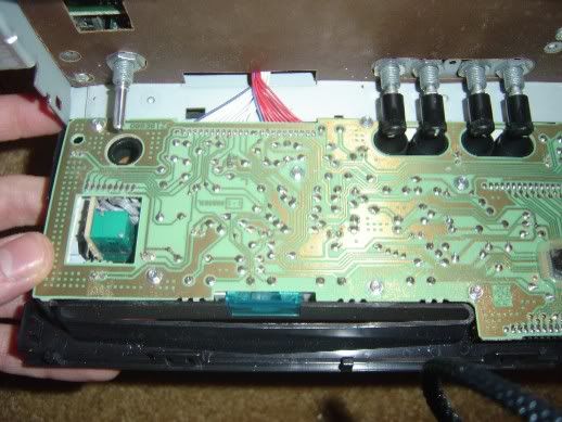
I placed the radio on my homemade workbench in my apartment and let the face droop off as to allow easier access to it. There are 7 screws holding the circuit board onto the face. Remove these and the face will be released from the board, as well as the blue plastic piece for radios equipped with the CD player. The grey wires connecting these is coiled around itself. Rotate the face as to uncoil them and give yourself more room (you'll see what I'm talking about).
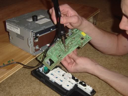
With this removed, begin removing the lights. This was done by touching the wood etcher with soldering tip ($20 bucks at Sears) to the back of the light leads until the solder pooled. Gently pull and they will come out) Do not worry about the LED polarity yet, I will provide a schematic for them later in this tutorial. While I removed them one by one, I installed my LED's in place to make sure they worked. You can remove all of the lights at once)
Now let the fun begin! To remove the cover on the radio, first pull out the Tune **** (it comes right off). Next, there are 8 taps located around the sides protruding from the face. Gently pry these up enough to release the face. Note: they face and circuit board are attached with wires!! Don't pull too hard.
I placed the radio on my homemade workbench in my apartment and let the face droop off as to allow easier access to it. There are 7 screws holding the circuit board onto the face. Remove these and the face will be released from the board, as well as the blue plastic piece for radios equipped with the CD player. The grey wires connecting these is coiled around itself. Rotate the face as to uncoil them and give yourself more room (you'll see what I'm talking about).
With this removed, begin removing the lights. This was done by touching the wood etcher with soldering tip ($20 bucks at Sears) to the back of the light leads until the solder pooled. Gently pull and they will come out) Do not worry about the LED polarity yet, I will provide a schematic for them later in this tutorial. While I removed them one by one, I installed my LED's in place to make sure they worked. You can remove all of the lights at once)
03-16-2005, 01:22 AM
#3
Le Mans Master
Thread Starter
With the board lightless, it's time to fabricate our LED's with resistors small enough to fit on the board. This requires skill and a steady hand!
I used the 5 mm LED's because I felt that they would disperse the light better. I originally painted their tips black to dissipate the light but this made them too dim, so I sanded that off... Live and Learn...
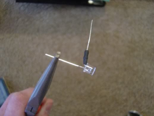
Follow the pictures on how to cut these down and solder them up. I used a regular soldering gun for this... On a quick note, the resistor goes on the longer lead (+) from the LED! I used the heat shrink to protect the LED from touching other stuff on the board.
5mm vs. 3mm
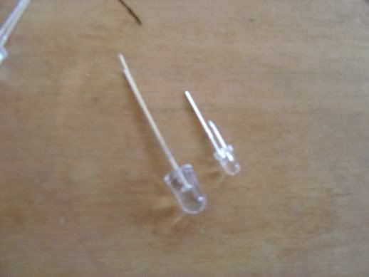
cut 5mm vs. 3mm
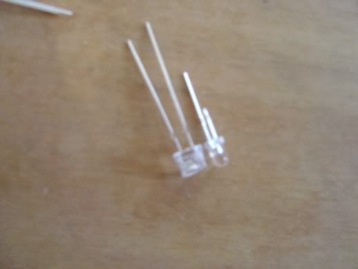
pos leg bent
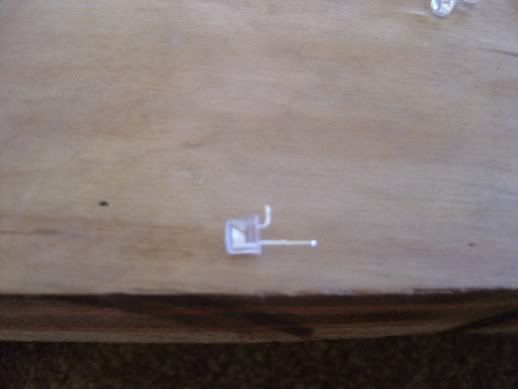
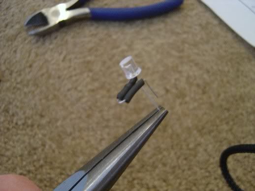
resistor soldered on
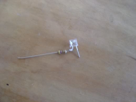
Heat Shrinked
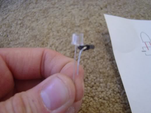
Bent around for board with more heat shrink
I used the 5 mm LED's because I felt that they would disperse the light better. I originally painted their tips black to dissipate the light but this made them too dim, so I sanded that off... Live and Learn...
Follow the pictures on how to cut these down and solder them up. I used a regular soldering gun for this... On a quick note, the resistor goes on the longer lead (+) from the LED! I used the heat shrink to protect the LED from touching other stuff on the board.
5mm vs. 3mm
cut 5mm vs. 3mm
pos leg bent
resistor soldered on
Heat Shrinked
Bent around for board with more heat shrink
Last edited by CUlookin; 03-16-2005 at 01:25 AM.
03-16-2005, 01:22 AM
#4
Le Mans Master
Thread Starter
I had an army of these things when I was done...
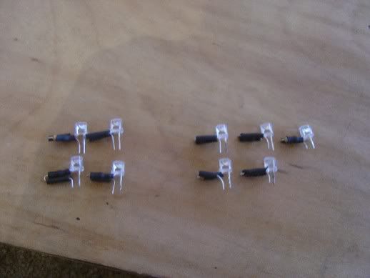
Now it's time to solder these guys onto the board... GOOD LUCK!! Here�s a diagram of the polarity of each LED.
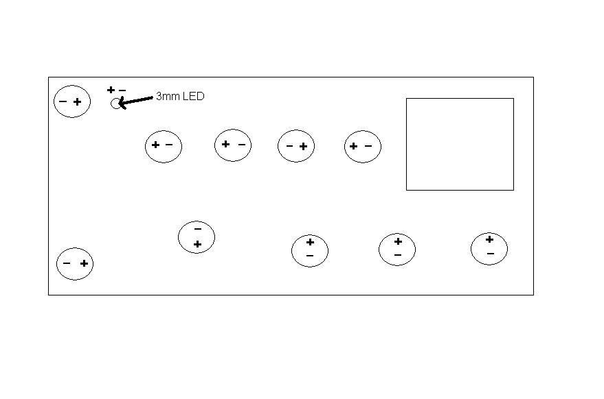
Simply reverse what you did for the bulbs. If you need more solder, use it sparingly! I twisted the resistors in such a way as to try to avoid contact with other things. Test the board with a 9V to check to make sure everything works...
I also replaced the small 3mm LED on the board with one of my 3mm Blue LED�s. DO NOT TOUCH THIS WITH THE 9V (unless you have an inline resistor� it will BLOW!)
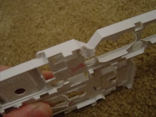
After you�re all done with soldering, some custom work must come into play. Remove the white piece from the face of the unit with a pick or flat head screwdriver
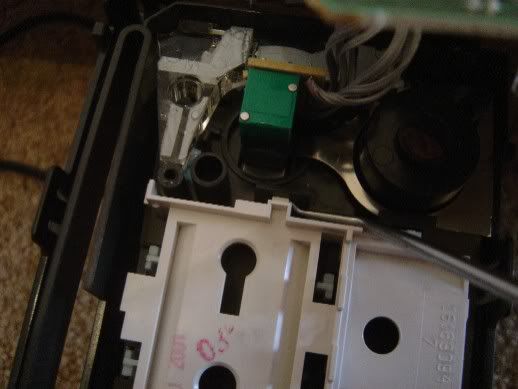
Notice that blue "window like" plastic, LEAVE IT!! I tried it both ways and this stuff helps disperse the light very effectively!
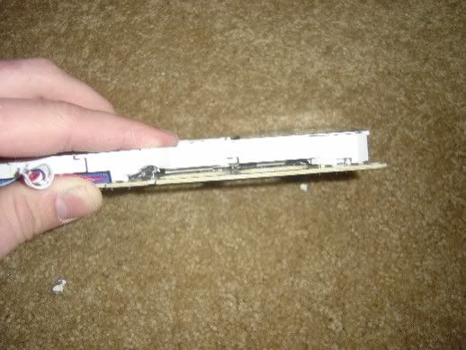
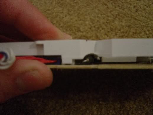
You'll have to shave down the white plastic piece to allow room for the resistors.
Now it's time to solder these guys onto the board... GOOD LUCK!! Here�s a diagram of the polarity of each LED.
Simply reverse what you did for the bulbs. If you need more solder, use it sparingly! I twisted the resistors in such a way as to try to avoid contact with other things. Test the board with a 9V to check to make sure everything works...
I also replaced the small 3mm LED on the board with one of my 3mm Blue LED�s. DO NOT TOUCH THIS WITH THE 9V (unless you have an inline resistor� it will BLOW!)
After you�re all done with soldering, some custom work must come into play. Remove the white piece from the face of the unit with a pick or flat head screwdriver
Notice that blue "window like" plastic, LEAVE IT!! I tried it both ways and this stuff helps disperse the light very effectively!
You'll have to shave down the white plastic piece to allow room for the resistors.
Last edited by CUlookin; 03-16-2005 at 01:25 AM.
03-16-2005, 01:23 AM
#5
Le Mans Master
Thread Starter
After your done this, it's time for reassembly. This part was hard to say the least. I found the best way to do this was to put the white plastic piece on the board itself. After it was all lined up, I carefully put it into the face (the white piece will snap in). Make sure you don't forget the blue plastic piece (I put this is after the face and board were together by lifting the board up a little and sliding it in).
Replace the 7 screws and snap the cover back on... Your almost there!!
Put on the Tune **** and reinstall the radio in the car by hooking the plugs back into the sockets (and 12 disc cord if equipped). Reinstall the rest of the car in the reverse order as mentioned above!!
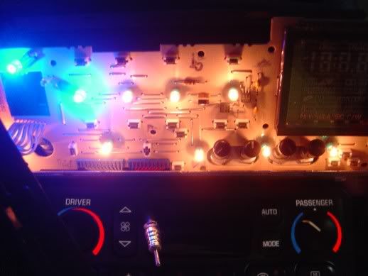
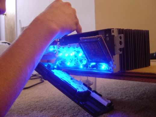
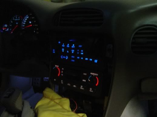
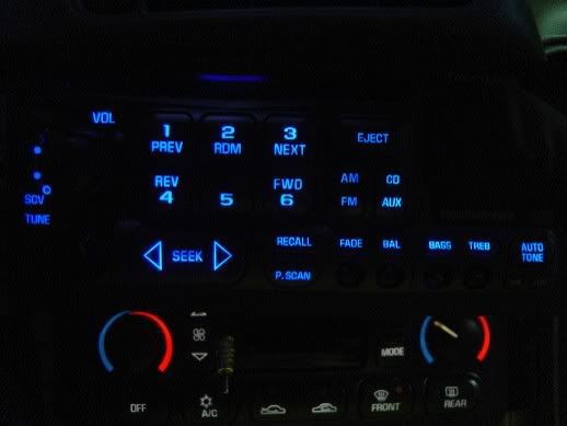
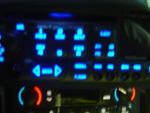
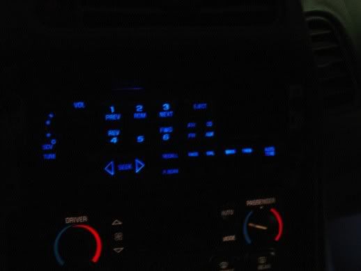
Here's the final product. Although it appears the radio has bright spots, I assure you there are none! It's just how the camera picked up the light so I included a blurry one that shows it's true effect. Trust me, it looks REALLY good and was worth my effort, but definately not Dave's (MyVetteDream)... Next week I�m doing the HVAC and DIC, but for now I�m packing for Florida� I need a break!
(This pics DON'T do it justice, you really need to see it in person...)
I want to thank Doug (WhiteC5Vette) for help with the wiring by sending me diagrams and Carelton (Spdkilz ~ spdkilz.com) for countless help through the whole LED process. Check out his website, it�s tight! I couldn�t have done it without you all!
Now just a quick word of advice... GO OUT AND BUY AN AFTERMARKET RADIO... with that said, Enjoy!
See you guys in a week or so, Spring Break starts tomorrow afternoon
Rob :
:
Replace the 7 screws and snap the cover back on... Your almost there!!
Put on the Tune **** and reinstall the radio in the car by hooking the plugs back into the sockets (and 12 disc cord if equipped). Reinstall the rest of the car in the reverse order as mentioned above!!
Here's the final product. Although it appears the radio has bright spots, I assure you there are none! It's just how the camera picked up the light so I included a blurry one that shows it's true effect. Trust me, it looks REALLY good and was worth my effort, but definately not Dave's (MyVetteDream)... Next week I�m doing the HVAC and DIC, but for now I�m packing for Florida� I need a break!
(This pics DON'T do it justice, you really need to see it in person...)
I want to thank Doug (WhiteC5Vette) for help with the wiring by sending me diagrams and Carelton (Spdkilz ~ spdkilz.com) for countless help through the whole LED process. Check out his website, it�s tight! I couldn�t have done it without you all!
Now just a quick word of advice... GO OUT AND BUY AN AFTERMARKET RADIO... with that said, Enjoy!
See you guys in a week or so, Spring Break starts tomorrow afternoon
Rob
:
Last edited by CUlookin; 03-16-2005 at 01:36 AM.


 , you do have infinite patience... I took the easy way out and bought a HU that already had the blue LED's to match the others
  03-16-2005, 02:37 AM
#8
Burning Brakes


Looking GREAT Rob! I am glad everything worked out  Thanks for the props
  There is like a little "LED" group running around the forum now...haha! Have fun on spring break...Mine was two weeks ago! I have nothing to look forward too now except summer when a few other things are going to get done to the Z06
Carleton
Thanks for the props There is like a little "LED" group running around the forum now...haha! Have fun on spring break...Mine was two weeks ago! I have nothing to look forward too now except summer when a few other things are going to get done to the Z06 Carleton
03-16-2005, 06:23 AM
#9
Supporting Tuner


That is an awesome write up Rob!! That's for the kudos - hey!, just trying to give back to this forum a little of all the excellent things it has done for me. Glad I could help.
On a scale of 1 to 10, this mod is a 11 and way, way 
Man, you do have infinite patience!!
Take care and have a good spring break
Stephen
On a scale of 1 to 10, this mod is a 11
and way, way Man, you do have infinite patience!!
Take care and have a good spring break
Stephen
 03-16-2005, 08:44 AM
#12
Safety Car

Member Since: Feb 2004
Location: Rochester MN
Posts: 4,208
Likes: 0
Received 2 Likes
on
1 Post
CI 5-6-7-8 Veteran
St. Jude Donor '04-'05-'06-'07
NCM Ambassador
Rob, Great post and very helpful info. Would you consider making it a Tech Tip so it is easier for folks to find in the future (we all know how the serach function is...)? Here is the link to submit a Tech Tip
03-16-2005, 10:26 AM
#13
Melting Slicks

Member Since: Jul 2002
Location: DFW Texas
Posts: 2,722
Received 63 Likes
on
35 Posts
CI 7-8 Veteran
CI 8 Car Show Winner
St. Jude Donor '07

You must have been reading my mind with that right up cause i just finished the doors, dic, tc button ,mirror and trunk switch, ordered more for the hvac and was waiting for you to complete your radio you mention before, great job on the write up, and thanks for posting, 3 more days and ill have enough led's to finsih things off. ive done everything in blue. it looks awsome!!!!!!!!!
03-16-2005, 10:39 AM
#14
Race Director

Member Since: Feb 2004
Location: HOW FAST WAS I GOING OFFICER? Los Angeles Hating GM Dealership Service Dept.'s Since Sept. 2004
Posts: 11,651
Likes: 0
Received 6 Likes
on
5 Posts
St. Jude Donor '04-'05-'06-'07
Outstanding write up Rob! Thanks for taking the time to do it. 
Now ... I have an Alpine IVA-D900 headunit ... can you do mine next?
Dave Q.
Now ... I have an Alpine IVA-D900 headunit ... can you do mine next?
Dave Q.
03-16-2005, 10:43 AM
#15
Melting Slicks
Member Since: Jul 2002
Location: DFW Texas
Posts: 2,722
Received 63 Likes
on
35 Posts
CI 7-8 Veteran
CI 8 Car Show Winner
St. Jude Donor '07
Originally Posted by MyVetteDream
Outstanding write up Rob! Thanks for taking the time to do it.
Now ... I have an Alpine IVA-D900 headunit ... can you do mine next?
Dave Q.
Now ... I have an Alpine IVA-D900 headunit ... can you do mine next?
Dave Q.

 03-16-2005, 11:31 AM
#16
Supporting Tuner
My Sony head unit can change through 12 colours
EG
EG


