The Forced Induction Crankcase Evac Thread
#61
Tech Contributor
Yes. You are mixing the "clean"& the "dirty" side of the crankcase evac system rendering it inoperative. You are venting excess pressure to the air....but no evacuation or flushing is occurring and unless you have a SD tune you have fuel trims hunting for stoic.
Need more details? Just ask and we can guide you through it.
Need more details? Just ask and we can guide you through it.

Unless you have a really crappy, dirty or totally undersized air filter, your system has no vacuum when the vehicle's under boost correct? Having some sort of restriction between the blower inlet and air filter is the only way you're going to have any vacuum there.
#62
? not following you.......if you are using the RX dual valve system while not under boost the vacuum from the intake manifold provides evacuation. As soon as the intake manifold becomes pressurized from boost, the primary check valve closes and the secondary valve opens using vacuum from the inlet side of the head unit. If you are connecting to the air filter then you are correct as the filter will not allow enough suction to do anything. If you install it correctly you are tapping into a spot just before the inlet turbine on the head unit and the venturi effect will give you between 8-12" of vacuum when measured there (see a few of the others on here that have run vac guages and measured).
Since you have a SD tune you have no MAF related fuel trim issues like those with the clean & dirty sides mixed together do.
You description said you are running both the clean and dirty side together if you described it accurately.
Since you have a SD tune you have no MAF related fuel trim issues like those with the clean & dirty sides mixed together do.
You description said you are running both the clean and dirty side together if you described it accurately.
#63
You need fresh air pulling through the motor from the left side valve cover and out the right side valve cover. Right now your just letting the blow by breath so you don't push oil out the front and rear seals, your motor needs to be aired out with fresh air to get the contaminated gases out! Its like your home filled with smoke and only 1 window open! but if you open 2 windows one on each side of the home it will get the cross air flow and blow the smoke out faster  Correct me if I'm wrong just trying to help
 Correct me if I'm wrong just trying to help

#64
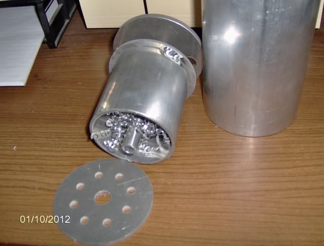
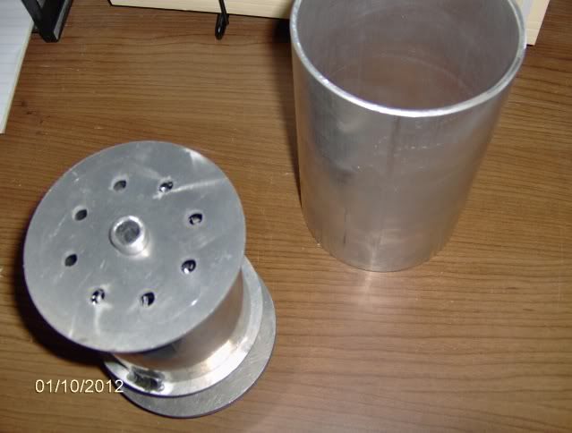
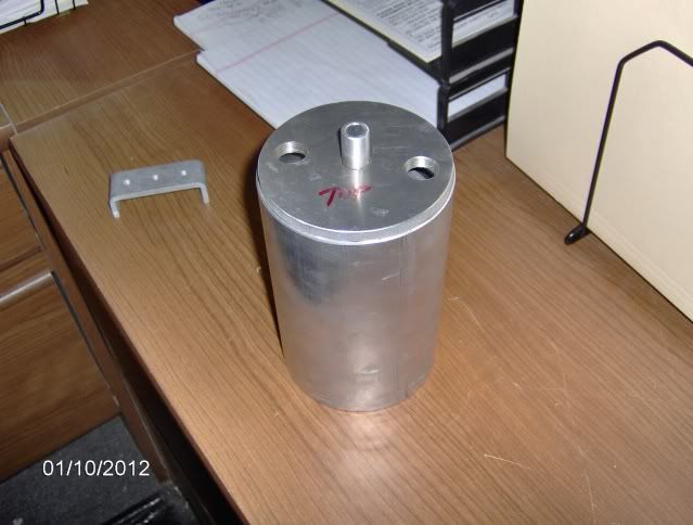
Here are some pictures of the unassembled separating system for big boost turbo or front mount SC's:
Shows the inner components:

Assembled but not in the canister...the bottom is facing up:

From the top. It comes with -8 or -10 AN fittings and inline flow control checkvalves:

It is large and not for the avg street build.
4" wide x 7.5" high with triple baffleing and good to 1200 hp turbo or front mount SC.
Shows the inner components:

Assembled but not in the canister...the bottom is facing up:

From the top. It comes with -8 or -10 AN fittings and inline flow control checkvalves:

It is large and not for the avg street build.
4" wide x 7.5" high with triple baffleing and good to 1200 hp turbo or front mount SC.
Last edited by The Bat Car; 01-10-2012 at 04:50 PM.
#65
Team Owner


Member Since: Jan 2007
Location: cookeville tennessee
Posts: 28,847
Received 1,762 Likes
on
1,529 Posts

Here are some pictures of the unassembled separating system for big boost turbo or front mount SC's:
Shows the inner components:

Assembled but not in the canister...the bottom is facing up:

From the top. It comes with -8 or -10 AN fittings and inline flow control checkvalves:

It is large and not for the avg street build.
4" wide x 7.5" high with triple baffleing and good to 1200 hp turbo or front mount SC.
Shows the inner components:

Assembled but not in the canister...the bottom is facing up:

From the top. It comes with -8 or -10 AN fittings and inline flow control checkvalves:

It is large and not for the avg street build.
4" wide x 7.5" high with triple baffleing and good to 1200 hp turbo or front mount SC.

 Only kinding man I will be putting the D/cans on the car this weekend. Robert
#66
Drifting


I guess if you want to run all that oil vapor through the blower, IC, engine at full load go right a head. Catch cans don't do THAT good of a job at oil seperation, especially under high flow. I'd like to see crankcase pressure numbers under load to see if it can actually pull vac on the engine though. Better run a big line.
Factory turbo cars have done this type of thing for years without the catch can in between. For emissions they need to keep a closed system, but end up with oil all over the intake track, not just in the intake manifold.
Factory turbo cars have done this type of thing for years without the catch can in between. For emissions they need to keep a closed system, but end up with oil all over the intake track, not just in the intake manifold.
#67
Why are you talking about fuel trims "hunting for stoich" here?
Unless you have a really crappy, dirty or totally undersized air filter, your system has no vacuum when the vehicle's under boost correct? Having some sort of restriction between the blower inlet and air filter is the only way you're going to have any vacuum there.
Unless you have a really crappy, dirty or totally undersized air filter, your system has no vacuum when the vehicle's under boost correct? Having some sort of restriction between the blower inlet and air filter is the only way you're going to have any vacuum there.
I remember when I first got my breather from ECS I hooked up HPtuners and saw a change but it wasn't a lot. That was a long time ago though...
#68
Premium Supporting Vendor
Member Since: Oct 2004
Location: Providing the most proven supercharger kits for your C5/6/7 609-752-0321
Posts: 23,321
Received 1,090 Likes
on
658 Posts

I have had the discussion with several customers about the use of a breather and tuning. (the unmetered air)
Basically yes it is unmetered air, where as the factory set up pulls it's air from after the MAF-before the TB so it is not. However, the amount of air is so minimal being pulled threw a PCV/check valve.
It is also a constant value, so it is very easily tunable. Definitely not something to be in the least bit concerned about IMO.
#69
Tech Contributor
I think what he means is if you add the oil cap valve cover breather and you are still running your MAF, your STFTs are going to change because of the unmetered air.
I remember when I first got my breather from ECS I hooked up HPtuners and saw a change but it wasn't a lot. That was a long time ago though...
I remember when I first got my breather from ECS I hooked up HPtuners and saw a change but it wasn't a lot. That was a long time ago though...
For the record, I completed my changes to my existing valve covers, adding -8AN ports to the valve covers and baffles and have driven the car quite a bit. Now mostly only water comes out when I crack the drain open.
I still have new valve covers in the works. I'll be picking them up next week and off to powder coat.
Bat Car dude, since you're deeper into this than anyone in the thread and have spoken about contaminating the oil by not pulling fresh air through the crankcase and the damage caused by it, I'm wondering where you gathered your evidence from. Oil analysis by chance? I would love to see all of the evidence you've gathered from your studies. I think it would be helpful. So far I've made the decision to stay with my current configuration, but that may change depending on what you bring to the table.
Next issue is: how much flow do we really need? In other words, what size ports is necessary in order to satisfy a purpose-built F/I motor? I'm aware the demand will vary based on ring gaps, displacement and cylinder pressure, but how about a range here?
Say an "average" 346 with .027" ring gap on the top ring, running 17psi boost and making 800RWHP.
Then change to a 434 with a .028" ring gap making 20psi boost and making 1100RWHP.
#70
I guess if you want to run all that oil vapor through the blower, IC, engine at full load go right a head. Catch cans don't do THAT good of a job at oil seperation, especially under high flow. I'd like to see crankcase pressure numbers under load to see if it can actually pull vac on the engine though. Better run a big line.
Factory turbo cars have done this type of thing for years without the catch can in between. For emissions they need to keep a closed system, but end up with oil all over the intake track, not just in the intake manifold.
Factory turbo cars have done this type of thing for years without the catch can in between. For emissions they need to keep a closed system, but end up with oil all over the intake track, not just in the intake manifold.

Trims are always bouncing around. They could change with an SD tune as well as MAF tuning. Changes in vacuum more than 1.5" will move you to a different cell at idle. I know you're aware the trims are based on feedback coming from the 02's and while we try to zero them out, they will never stay zero'd out.
For the record, I completed my changes to my existing valve covers, adding -8AN ports to the valve covers and baffles and have driven the car quite a bit. Now mostly only water comes out when I crack the drain open.
I still have new valve covers in the works. I'll be picking them up next week and off to powder coat.
Bat Car dude, since you're deeper into this than anyone in the thread and have spoken about contaminating the oil by not pulling fresh air through the crankcase and the damage caused by it, I'm wondering where you gathered your evidence from. Oil analysis by chance? I would love to see all of the evidence you've gathered from your studies. I think it would be helpful. So far I've made the decision to stay with my current configuration, but that may change depending on what you bring to the table.
Next issue is: how much flow do we really need? In other words, what size ports is necessary in order to satisfy a purpose-built F/I motor? I'm aware the demand will vary based on ring gaps, displacement and cylinder pressure, but how about a range here?
Say an "average" 346 with .027" ring gap on the top ring, running 17psi boost and making 800RWHP.
Then change to a 434 with a .028" ring gap making 20psi boost and making 1100RWHP.
On builds like your talking we have had success with -6, but if ring seal is not excellent then we go -8 or -10 like the unit above. But for most builds the -6 (3/8"ID) has been fine to 900-1000 rwhp. Problem we see FAR to often are pinched ringlands & pistons damaged by detonation that are allowing far to much blow-by for any system do deal with. These make good power and seem to run well but a leak-down test (not a compression test) will pinpoint the problem cylinder(s).
Of course the tuners that do the damage never seem to acknowledge they went lean or added a little more timing than the combo could stand, and how many see knock sensors desensitized or turned off because the tuner was fight spark knock?

#71
Tech Contributor
Yes, years of oil analysis with the drag motors (Pennzoil was sponsoring one of the cars for a season and did analysis with every oil drain) and we have done them for years as well. The PPM levels of the abarsive carbon particles, unburnt fuel, and acid levels were the ones we look at the closest and then iron, brass, etc. for wear indicators.
On builds like your talking we have had success with -6, but if ring seal is not excellent then we go -8 or -10 like the unit above. But for most builds the -6 (3/8"ID) has been fine to 900-1000 rwhp. Problem we see FAR to often are pinched ringlands & pistons damaged by detonation that are allowing far to much blow-by for any system do deal with. These make good power and seem to run well but a leak-down test (not a compression test) will pinpoint the problem cylinder(s).
Of course the tuners that do the damage never seem to acknowledge they went lean or added a little more timing than the combo could stand, and how many see knock sensors desensitized or turned off because the tuner was fight spark knock?

Heck, if you don't have the data retained, I may just sample my oil and send it off and post it up. Then we'll all know what to expect on this side of the fence.
#72
Great suggestion....lets get an unbiased example. There are sevral good companies doing this for reasonable $ and results are pretty quick. I would really like to see it from the same car where it is the same amount of serivce on the oil, same driving (as close as possible) that is running kjust breathers or a breathered can and then switch to the proper evac system to show. :thumbsup:
#73
Instructor


Member Since: Dec 2006
Location: Minnesota Corn Fields
Posts: 168
Likes: 0
Received 0 Likes
on
0 Posts
Is there a way to use the front passenger side valve cover port for the fresh air source in conjuction with the breather? I don't like the looks of the breather on oil fill cap.
#74

#75
Instructor


Member Since: Dec 2006
Location: Minnesota Corn Fields
Posts: 168
Likes: 0
Received 0 Likes
on
0 Posts
#77
Instructor


Member Since: Dec 2006
Location: Minnesota Corn Fields
Posts: 168
Likes: 0
Received 0 Likes
on
0 Posts
So in non-boost, the intake manifold & blower inlet will pull vacuum on the outer two fittings?
And in boost the one-way valve in the outer fitting to the intake manifold simply closes and continues to pull vacuum on the other outer fitting from the blower inlet?
And in boost the one-way valve in the outer fitting to the intake manifold simply closes and continues to pull vacuum on the other outer fitting from the blower inlet?
Last edited by No Juice; 01-12-2012 at 05:53 PM.
#78
Instructor


Member Since: Dec 2006
Location: Minnesota Corn Fields
Posts: 168
Likes: 0
Received 0 Likes
on
0 Posts
How do I make sure to order the breather w/check valve not bonded to the cap?
Also how long are the hoses in the F-body kit? I plan to mount that down below as well.
Also how long are the hoses in the F-body kit? I plan to mount that down below as well.
#79


