
The True FI crankcase evac solution!


 12-01-2011, 09:28 PM
#44
Drifting


Member Since: May 2008
Location: Petal Ms
Posts: 1,621
Likes: 0
Received 2 Likes
on
2 Posts
St. Jude Donor '08-'11
I set this up like you said and I ended up with a dip stick blown out and oil all over my engine 
I never had this problem with no catch can at all. You sure that is the correct routing?
I never had this problem with no catch can at all. You sure that is the correct routing?
On a LS1 turbo you run one line from the drivers side valve cover from the nipple on the rear part to the center fitting on the can, then cap off the pass ide valve cover fittings both the front & rear one. The breather kit provides the filtered fresh make up air then. Then from the intake manifold passenger side of the snout (plastic) there is a vacuum nipple. Connect that to one of the outer fittings on the can (it is one of the dual checkvalves). The other checkvalve/outer fitting runs to as close to the turbo inlet as possible. Tap in a 1/4 NPT x 3/8" barb fitting so it is utilizing as much of the inlet side suction as possible. The closer the the air cleaner the less vacuum is realized.
The bolt should be included by RX, but we will make sure.
Hi Steve,
Both GM & Ford designed very effective oil separating cans in the past....some even used a centrifuge type spin to separate and filter the contaminates out of the collected oil and returned it to the crankcase. All were nixed for one reason or another. If you look into the GM LLT V6 intake manifold they have molded in a 1 pint capture bowel just inside the snout that can be cleaned during service.
I have a early 60's maserati mistral and it has the motor used to race LeMans in the late 40's/50's and it has a factory oil separator that kept it out of the intake manifold for the power, but they reintrodced it to the crankcase not knowing back then all the harmful compounds that were produced.
On todays industrial diesels this is the most effective system developed to date:
http://www.alfalaval.com/about-us/pr...separator.aspx
Pricey but it is amazing.
Although these are used on huge idustrial diesels, the propblem & solution remains the same.
Here is an excerpt:
Catalytic fines, a hazardous by-product of the refining process, are a particular concern in dealing with these oils, as failure to remove them can lead to increased wear and permanent engine damage.
Lubricating and marine diesel oils, shown to the right on the scale (LO/TP = lube oil trunk piston engine, LO/XH = lube oil cross head engine, GO/MDO = gas oil/marine diesel oil), are of lower and more consistent density. While still complex and potentially impure, they have a known composition and can be handled by a less adaptive separator. The impurities involved are usually limited to soot and particles, and if water is present, it is generally only freshwater condensate.
Alfa Laval�s S- and P- separators approach this scale from opposite ends, as can be seen from the illustration above. By addressing oil treatment in this manner, Alfa Laval lets shipyards, engine builders and ship owners choose the level of performance and automation that matches their oil and application needs.
12-03-2011, 12:43 AM
#45
Burning Brakes


I used to run two cans,
This as been on my car for some very hard driving and a long trip.installed on a fresh forged motor and it is really doing the job.no fouled plugs cleaner intake and drains very easily.This a guy that knows what he is building.Mine is a ls6 fixed orifice set up.
Thanks Tracey,
Mike
This as been on my car for some very hard driving and a long trip.installed on a fresh forged motor and it is really doing the job.no fouled plugs cleaner intake and drains very easily.This a guy that knows what he is building.Mine is a ls6 fixed orifice set up.
Thanks Tracey,
Mike
12-03-2011, 05:05 PM
#46
 12-03-2011, 05:59 PM
#47
Drifting
Member Since: May 2008
Location: Petal Ms
Posts: 1,621
Likes: 0
Received 2 Likes
on
2 Posts
St. Jude Donor '08-'11
I think I found the problem, compression was 95 in cylinder four...
Are you using the RX dual valve system? If so the checkvalves prevent any excess pressure and evac in both boost & non boost operation. PM me detailed pictures so I can look at your routing....someting is not right for sure. I just got back from PRI so going through hundreds of emails & PM's right now.
12-05-2011, 06:45 PM
#48
Safety Car


Alright guys it's true! I can actually keep my engine bay clean now with this system. No more oil mist. I drove all over the place today and could not get it to mist once or smoke. Tracy did a great job of explaining everything he was doing and why. I enjoyed checking out the cars and Tracy even helped resolve my recent starter issues. So far so good. Now I just have to fix some other little electrical issues.
Much thanks to The Bat Car Owner !!!!! I am getting my Supra PCV setup done there next...
Much thanks to The Bat Car Owner
!!!!! I am getting my Supra PCV setup done there next...
12-07-2011, 05:34 PM
#49
Have this system for any single & twin turbo applications and the ECS & A&A front mount SC kits. The ONLY solution for under $200 that properly addresses crankcase evacuation under both boost & non-boost operation.
12-07-2011, 05:59 PM
#50
Le Mans Master

I want a polished one for my Magnacharged LS-7, I only need the 2 hose unit since I always have vacumn at my throttle Body. With breather cap please, shipped to 95687
 01-14-2012, 11:32 AM
#52
Melting Slicks


... Maybe i missed the reasoning for this, but couldnt one with an AA/ECS setup run a single valve setup and just route to the filter in front of the charger? Or does the BOV cause issues with this?
I would just think this area would create vaccum at all times, boost or not.
I would just think this area would create vaccum at all times, boost or not.
01-18-2012, 12:32 PM
#53
... Maybe i missed the reasoning for this, but couldnt one with an AA/ECS setup run a single valve setup and just route to the filter in front of the charger? Or does the BOV cause issues with this?
I would just think this area would create vaccum at all times, boost or not.
I would just think this area would create vaccum at all times, boost or not.
The dual valve unit ensures evac at both boost & non-boost operation.
Here is the latest "Stage Two Monster" unit for big boost radical builds. Comes with either -8 or -10 AN fittings and inline high flow checkvalves:
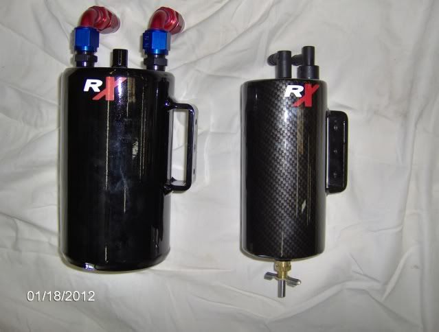
Fitment is difficult and it is not a easy bolt on install, but is the ultimate.
02-24-2012, 07:26 PM
#54
Team Owner

I had my poor lil' 1998 LS1 tuned when I added a 2001+ intake manifold. The tuner "cleaned up" the intake by eliminating some of the evap/air lines, rerouting PCV...
...and now I've got some kind of weird vacuum condition which makes the oil filler cap very, very hard to remove when the engine is warm.
Would your single-valve system and the optional breather check valve get rid of this condition, aside from probably being a "hunting gnats with an elephant gun" option?
02-27-2012, 02:27 PM
#55
Pro


I'v seen two methods to get vacuum in this thread.
1: using a 45' angled fitting in the intake (similar to exhaust gas evacuation)
2: Using the vacume port on equipped turbos to pull vacuum
I have a remote mount turbo (STS). Can adequate vacuum be pulled from that far back in the car? I'm running ~ 7lb, would that be enough for the 45' valve in the intake?
02-28-2012, 09:15 PM
#56
Got my kit from ColoradoSpeed about a week ago...couple of questions:
1) How do I know if I got the right kit for my A&A supercharger? I don't see a longer bolt included so I'm wondering if I got the normal kit
2) Where and how am I supposed to tap the back drivers side valve cover?
1) How do I know if I got the right kit for my A&A supercharger? I don't see a longer bolt included so I'm wondering if I got the normal kit
2) Where and how am I supposed to tap the back drivers side valve cover?