When you click on links to various merchants on this site and make a purchase, this can result in this site earning a commission. Affiliate programs and affiliations include, but are not limited to, the eBay Partner Network.
If the vacuum pump is turning on and off with the key on say every 10 seconds more or less (the vacuum pump if no leaks will actually turn on for a few seconds and then shut off for several minutes) you have a vacuum leak.
1. With plenum off (with key on) disconnect the vacuum lines one at a time starting from the pump and hold your finger over the end of the vacuum line. The pump should shut off and stay off. If the Vacuum Pump does not stop cycling the leak has been located. If the Vacuum Pump does stop cycling, the connections checked are in good condition and continue to the next Vacuum connection.
2. Now go to the next suspect connection and do the same. Once you get to the plenum Connection (the vacuum line that goes under the Plenum next to the Alternator, you have to remove the Plenum to investigate further).
3. A possibility not yet discussed.........
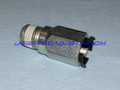
There is a Vacuum Check Valve under the Plenum that isolates the Vacuum Pump from the Plenum Vacuum as long as the Vacuum Pump is pulling greater vacuum than the Plenum.
With the Key On but engine NOT running the Vacuum Check Valve can be tested for proper operation without removing the Plenum as follows........
The Plenum source of vacuum is located on the drivers side center of Plenum. Disconnect that Vacuum Connector from the Plenum and place finger over end of vacuum line rubber connector to see if the Vacuum Pump quits cycling. With Key ON the Vacuum Pump will cycle every two or three seconds with that vacuum rubber connector NOT blocked and failed vacuum check valve. With that Vacuum Rubber Connector blocked if the Pump now stops cycling you have located the Vacuum Leak which actually is a faulty check valve located under the Plenum. If disconnecting that Vacuum line results in the Vacuum Pump not Cycling without blocking with finger, the Vacuum Check Valve is operating correctly.
The Plenum has to be removed to replace that check valve.
This faulty check valve can fail intermittently and will then cause intermittent operation of the Vacuum Pump. The test as described is a simple test and can be conducted with the Plenum in place.
4. Once you get just past the leaky connection, holding your finger over the end of the vacuum line will not stop the pump from recycling. You have now found the leaky connection
Usually the rubber connectors leak from age (hardened rubber).
I have a 90' and 91' with identical Wilwood/C5 Z06 Brake Conversions as shown. A-Molds fit this conversion without any issues other than the redistribution of wheel weights. The question came up regarding Stock Sawblades fitting this Wilwood/C5 Z06 Brake Conversion.
I measured a stock Sawblade wheel and found the inside diameter is about identical to A-Molds at the two critical locations of the Calipers (see 13B below).
I also measured the spoke Offset from the Hub and found it to be .75 inch as compared to 1 inch for A-Molds (see 13A below). When installing the Sawbade wheel the spoke of the Sawblade JUST came into contact with the C5 Z06 Caliper as shown. In other words I would say the offset of the stock Sawblade wheel is 1/4 inch short of what would be required (3/4 inch vrs 1 inch).
It would be easy to place a 1/4 inch spacer on the Hat of the Wilwood Rotor but you would then be 1/4 inch shorter on the stud length for the wheel nuts which you end up with 1/4 inch less than the bit over 1/2 inch threaded contact now (as I view my Hubs with the Wilwood Rotors installed with Hats).
The inner wheel Clearance of this brake setup using A-Molds was identical (90' and 91'). For OTHER wheels (other than A-Molds and Sawblades) the information below will apply. See item # 13A and 13B of ZR-1 (90' and 91') Wilwood Rotors and C4 to C5-Z06 Conversion for do it your self wheel measurements to determine if your wheels will fit this Brake Set Up. Copied here
13. Wheel Dimensions that will fit on this brake Set-Up. This would be the limit of a wheel inner dimensions which would fit/clear this Brake Caliper Set-UP.
Rather than try to measure the offset and the maximum radius of the Caliper it was easier just to measure the A-Mold wheel which just clears the spokes as well as the Caliper outer radius as shown below. I would say this is Minimum Clearance. The clearances of this Set-Up is on the order of 1/4 inch on spoke and 1/8 inch on wheel inner radius so very close. There is slop in the Caliper pins riding in the bracket so this clearance is definitely required.
A. Spoke Offset.
The Spoke Offset from hub surface is 1 inch at the widest part (outer edge) of the Caliper.
The wheel weights are located on the inner rim and single stacked.
B. Wheel inner diameter.
Two Inner wheel diameters are shown. The one on the left is the wheel diameter at the hub surface which is 15.25 inches (this would coincide with the the radius of the outer part of the caliper) . The Second wheel diameter on right is the wheel diameter at 4.5 inches up from the spoke where the inner (larger radius) part of the caliper which is larger radius sits which dimension is 15.75 inches.
See Post 270 for the latest information on Wilwood 140-8337 Brake Kits which do fit the 1990 Standard Corvette and 1990 ZR-1 with Sawblades using 1/8" Spacers between the Wheel and Hat Post 270 - Wilwood 6 Piston Brakes with 13" Rotors and Wheel Alignment
Our tensioners are made by Dayco. So I called them and got in contact with a wonderful guy named Randy. He verified my thoughts that the LT1 and LT4 tensioners have the same internals as our tensioner. So I ordered a new Dayco tensioner from rock auto with a discount coupon and came out to a total of $38 and it came with the pulley with the belt guides so that was handy because all you can buy right now is the smooth pulley.
One 10 inch cresent wrench (Box Wrench is best), One vice, Air compressor, Angle Grinder (with Cut Off wheel). The best tool for cutting the SS Braided Hose is a Small Angle Grinder (with Cut Off wheel) which does not fray the SS braids on the hose ends. It is also best to use an appropriate size Box Wrench on the Hose Fittings (box end) to minimize leaving marks on the fittings. [B]I use Aeroquip Reusable Fittings and SS Braided hose from Summit Racing.
To remove existing 12AN x 3/4 NPT fittings from the Oil Filter Housing use a 1-1/8 inch box wrench (combination box/open end) with the box end on the fitting interlocked with a 3/4 inch box wrench on the other end. This will provide the leverage/torque without excessive horizontal pressure to remove the fittings. I use permatex when installing the New 10AN x 3/4 inch NPT fittings into the Oil Filter Adapter (lower fitting first). Let the ZR-1 sit over night before removing the existing Oil Cooler Hoses to minimize oil spilling.
I use all 10AN Aeroquip Reusable Fittings and 10AN Hose....The 10AN SS Braided hose I use has ID of 9/16 inch and the 12 AN SS Braided Hose has ID 5/8 inch. As it turns out.....the 12AN hose with 5/8 inch ID is identical to stock Oil Cooler Hose having ID of 5/8 inch. Also I noted the ID Fittings on the stock Oil Cooler Hoses on the Oil Cooler end where the tubing is located is less ID than the SS Braided 10AN Oil Lines.
The Stock Oil Cooler hoses have 6 inches of steel tubing on Oil Cooler end that are identical in ID (9/16 inch) to SS Braided 10AN. Further, the Stock Oil Cooler hoses are 17 inches long as compared to 13 inches long for SS Braided Oil Cooler Hoses. The Oil Filter Adapter end of the Stock Oil Cooler hoses is only about 1/2 inch ID at the fittings. Which if you add all that up I would say the total head loss in the stock Oil Cooler hoses is about identical to the SS Braided 10AN with Aeroquip 10AN Fittings.
2. Measuring SS Braided Hose Length.
A. Follow Step #3 below and make up one end of each SS Braided Hose (cut longer than required to reach the Oil Cooler Adapter) with the 45 degree Aeroquip Reusable Hose Ends.
B. Install and snug up but not tight the 45 degree Aeroquip 10AN Hose ends onto the 10AN x 3/4 inch NPT fittings installed into the Oil Filter Adapter.
C. Take the free SS Braided Hose ends curved freely around the radiator housing as they would look in the final installation. Mark the SS Braided Free Hose Ends along Red Line A and Red Line B as shown.
D. Cut these Hose Ends about 1/4 inch longer than that mark.
E. Install the 90 degree Aeroquip 10AN hose ends as in step #3 below.
F. After installation of all four 10AN Aeroquip hose ends is complete, install the 90 degree hose ends on the Oil Cooler Adapter.
G. Tighten the 10AN Fittings into the Oil Cooler Adapter (18mm x 1.5 or 6AN Straight Fittings).
H. Tighten the 10AN 90 degree Aeroquip Fittings onto the 10AN male fittings of the Oil Cooler Adapter at the angles shown by CD and EF. Make sure there is a small gap between the bottom 10AN 90 Degree Fitting and the AC Line and the two 10AN 90 degree fittings (top and bottom)
I. Install the other end of the SS Braided Hoses 45 degree Aeroquip Fittings onto the respective Oil Filter Adapter male fittings and tighten.
J. Now making sure the "O" rings are in place on the Oil Cooler Adapter (I use Permatex on the adapter "O" ring face), position and the adapter on the face of the Oil Cooler and insert the 6mm x 1.0 x 35 mm SS Allen head bolt with SS washer into the Oil Cooler Adapter and tighten the bolt. No modification of the Fiberglass Radiator Housing is required since the Oil Cooler Adapter is installed on the Oil Cooler AFTER the fittings are connected and tightened on the Oil Cooler Adapter.
3. General SS Hose Assembly with Re-Usable Fittings.
A. Place SS Braided hose in vice and cut SS Braided hose to length using Angle Grinder with Cut Off wheel. Angle grinder is preferred since minimal SS wires are left free of the cut.
B. Make sure NO SS Braided wires enter the hose end and make sure ALL loose SS Braided wires are ground flush with end of hose. Keep the hose in the vice with about 2 inches on the free end out of the vice. (Clean the inside of the hose end Cut Off before going further with Cotton Cue Tip .
C. Take the AN reusable hose fitting and unscrew the male part from the female part. The other end of the male part will have an NPT pipe thread or "O" ring seal thread size (AN) as desired.
D. Take the AN reusable hose fitting female part and screw/push onto the SS Braided hose (counterclockwise) by hand pushing onto the hose as you rotate the female hose fitting counterclockwise. Aeroquip Nickel Plated Aluminum Reusable Fittings are not threaded but ARE serrated requiring a push onto the hose only. Make sure ALL SS Braids are inside the hose fitting just pushed onto the hose.
E. Screw/push the AN female reusable hose fitting onto the hose fitting such that the hose is at a depth into the female fitting as defined by the lines on the female fitting surface.
F. Lubricate the inside diameter of the SS Braided hose with oil through the end of the female fitting.
G. Insert the male reusable hose fitting into the lubricated hose through the end of the female fitting.
H. Push the male fitting into the hose as you rotate the male fitting clockwise using a cresent wrench (Box Wrench preferred). Once the threads are caught, continue rotating the male fitting into the hose untill approximately 1/16 inch space is left between the hexigon of the male fitting and female fitting.
I. Install the second hydraulic reusable hose fitting on the other end of the hose as per steps 2 through 8 above.
J. Last...but not least....take an air hose (Air Compressor) and blow the hose clear to make sure you have a clean assembly (if the SS Braided hose is not too long look through the hose end to end for any debree). You now have a SS Braided hydraulic hose with fittings good for maybe 2,000 psi hydraulic pressure more or less.
4. Parts Required for SS Braided Oil Cooler Lines with Re-Usable Fittings.
The SS Oil Cooler Lines are very easy to make up in SS Braided hose using Aeroquip reusable fittings and SS Braided hose available from Summit Racing. The Aeroquip Fittings are Swivel so self aligning when installing.
The first seven items can be found at Summit Racing.
Secondchance Design of Oil Cooler Adapter..................Jeffvette Design of Oil Cooler Adapter
I have never had one of these hydraulic lines with Aeroquip Reusable Fittings leak and they are much much tougher than original crimped fittings and easily replaced or adjusted if you want to at some point make them longer or shorter (the fittings are reusable and swivel). And......you will find a much better routing of the lines if you make them yourself by looking at the routing of the existing Hydraulic Lines. The Aeroquip Reusable Fittings come in all sizes and angles to fit any situation. You can make your own oil cooler lines as shown here and Power Steering Lines or any other hydraulic line you might need on the ZR-1.
As an aside, I use the similar Aeroquip reusable fittings and Aeroquip 1509 hydraulic hose on all my farm implements and tractors. I make up all my implement hydraulic lines often replacing relatively new lines that come with the implements with my own lines that are much more dependable under extreme usage. We are talking hydraulic pressures over 2,000 psi on the hydraulics of some of these implements when the cylinders reach the stops.
Once you experiment with making your own hydraulic lines with some using SS Braided hose you will never look back at buying ready made hydraulic lines again. All you need is a vice, hand grinder (or even a hack saw will work), and a couple box wrenches of appropriate size. Oh...and an air compressor to blow clean the lines after assembly.
5. The TRICK to Remove the 12 AN Flare Fittings.
Use a 1-1/8" 12 Pt Box Wrench with another Box Wrench for leverage. The issue using a Deep Socket is that the torque is applied too far out causing the socket to twist off the fitting. With the box wrench there is no twisting off the fitting with all torque applied directly to the fitting flats.
The two coolant manifolds attached to the injector housings should get warm within 30 seconds with engine running if the water pump is pumping coolant. If not......you have to get that air out of the water pump area (Air Locked Water Pump). SeeLT5 Air Locked Water Pump Simplified
1. Disconnect the drivers side Injector Housing Coolant Manifold "L" and tip it up. Fill that "L" with coolant and blow into that "L" forcing coolant into the water pump through the passenger side water pump inlet and passenger side Injector Housing Coolant Manifold.
2. Refill the Drivers Side "L" with coolant and do that trick a couple times until the coolant flows out of the drivers side Injector Housing Coolant Manifold where you have disconnect the "L".
3. Do NOT rely on the temperature gauge to tell you if the Water Pump is functioning. If the two Injector Housing Coolant Manifolds are NOT getting warm rather quickly (within 30 seconds), your coolant is NOT flowing.
4. Once the Water Pump is Pumping Coolant, ALL other air within the coolant system will rapidly be forced to the top of the radiator once the thermostat opens. That Air will be forced into the Coolant Reservoir located at the high point of the coolant system just in front of the passenger side firewall.Make sure that Coolant Reservoir is full at all times (once the engine is running that Coolant Reservoir becomes pressurized) so be careful in removing the "radiator" cap.
5. Keep a hand on both Injector Housing Coolant Manifolds making sure they continue to get hot after the initial warming (within 30 seconds). As the Injector Housing Coolant Manifolds get hot place your hand on the Radiator Hose (Coolant Connection To Radiator) indicating the thermostat has opened when the Coolant Connection To Radiator starts getting warm. At that time the rest of the Air in the Coolant System will purge itself as the engine heats up and coolant expands forcing all air into the Coolant Reservoir and ultimately into the Coolant Overflow container under the Passenger Side Headlight. After the engine is turned off as the engine cools, the Coolant will be topped off within the engine as the coolant is sucked back into the engine from the Coolant Overflow container under passenger side headlight.
Replacing Bolts in various Components and the use of Loctite
Some Tips of Replacing Bolts in various Components and the use of Loctite.
Clean, dry bolts with a couple drops of blue Loctite on bottom threads of bolts (Injector Housing) and thin coat of Permatex on gaskets (except when I have a gasket NOT exposed to coolant in which case NOTHING on gasket). Red Loctite on everything inside the Front Cover. Blue Loctite on Oil Pan Bolts. Nothing on Head Gasket and nothing on Plenum gasket since I have TB/Plenum coolant locked.
Actually I do not use any Loctite on my SS Allen Head Bolts (Cam Covers or Plenum). I use Aluminum Stat-O-Seal Washers on all Allen Head SS Steel Bolts installed in the Plenum and Cam Covers (including the IH Coolant Manifolds).
Aluminum Stat-O-Seal washers with molded Buna-N inner seals are much more reliable than the more common steel stat-o-seals. If the rubber portion fails to make contact all around the port, the aluminum will act as a crush washer, providing a reliable metal to metal seal. Use them to seal screws, bolts or plumbing fittings. The Buna-N seal is resistant to petroleum fuels and oils.
Before you tighten down the Plenum (with Plenum tipped up in front) and ALL vacuum lines, and DIS module connections in place....check your vacuum systems.
With all vacuum lines connected, turn key on and listen for vacuum pump to shut off. If it does not shut off, start at the closest vacuum line to the vacuum pump disconnecting the line and holding your finger over the end. If the pump shuts off the leak is on other side of that. Go to next fitting and do the same until you are past the leak wherein the vacuum pump will NOT shut off. You have now located the leak.
Also check your HVAC and Cruize Control Vacuum System (check ALL connections). Also check your EVAP Purge system connections (charcoal canister which is under drivers side headlight on your 90'). That single small vacuum port under front of plenum facing rearward (90' only) is for the Evap Purge System. The second larger vacuum port on drivers side lower front of plenum is the main vacuum line for the Charcoal Canister. The second Vacuum port right next to that Charcoal Canister port is your PCV Vacuum port.
With the key on, ground the pink wire in the green connector (third from drivers side) on ECM. Use a small finishing nail stuck in alongside the wire connector with an alligator clip pigtail attached to the end for grounding. This will activate the Secondaries which you can watch with the plenum tipped up in front before you bolt it down. This after you are sure you have NO vacuum leaks in the Secondary System. SeeSecondary Functional Test and Reconditioning the Secondary Actuators
You should eliminate TB coolant so you do not have to mess with coolant every time you remove the Plenum.
All you need is a 15/64 drill bit to pin the camshafts
You also need timing chain mechanical tensioners.
Or you can visually even get closer if you want to advance the pinning hole in the camshaft a bit past or before the pinning hole in the Camshaft Retainer.
I have removed the Heads with engine in car but then camshaft timing as well as Head Bolt Torque application is almost impossible with engine in car.
Pull the C-Frame, the Transmission, Bell Housing, exhaust manifolds....pull Plenum and IH to make it easy. I have actually installed the LT5 with Headers attached
Oh.....I pulled windshield wiper motor and cover off AC Evaporator just to get those out of the way for easy engine installation.
So.....you are pulling most oil through the Cam Cover Filters l at WOT and if you have a clogged air filter you are pulling even more vacuum at WOT from the Cam Cover vents but that is prolly just not a factor. Now if the Cam Cover Filter is clogged up, you might have a positive crankcase pressure since there is not much vacuum on the PCV system. The crankcase pressure would be greatest at WOT with the most gasses escaping into the crankcase around the rings.
In the case of a positive crankcase pressure you might see oil around the Cam Covers Or Oil in Spark Plug Area. Just guessing here to determine what can be done if the Cam Cover Filters get clogged upCam Cover Filters
It seems that the Crankcase pressure would be totally dependent on the condition of the rings. PCV valves, and Cam Cover Filters. The amount of gas passing through the PCV system and Cam Cover Vents is equal to the amount of gas passing past the rings at all times.
I switched from Scotch Brite to Marc Haibeck's new Cam Cover Vent filter material Cam Cover Filters
You can see a faint image around the first spark plug access hole where the "O" ring makes contact with Cam Cover.
Resizing Photos for Forum Posts and Reference Links
Resizing Photos for Forum Posts and Reference Links
ALERT
The BIG Trick for Photo Album Use on the Registry is.....
After you have selected 800 or 400 or other pixels using Paint (or other photo pixel resize software) on your computer and applied to any photo on your computer....and after you have uploaded that photo to your Registry Album of Albums.
Once the photo is in your Registry Album (resized by PAINT on your computer) you go to that Album and LEFT Click on the photo....It will then appear the size you PAINTED. You then select and copy the BB Code. Then Paste the BB Code into a post.
Another way is to LEFT Click on the photo......It will then appear the size you PAINTED. You then right Click and Select Copy. Left Click on Insert Image in the Post Heading and Paste the Copy in the Insert Image Box. Click on OK and the image will be Inserted where your curser was set before you selected Insert Image.
DISCUSSION 1. Photo Resizing for Forum Posts (this applies to Registry Albums which CF Albums are a bit different (see item #3 below).
It is assumed you have Paint on your computer. If so you can resize photos on your computer to any size you would like to see in a post using Paint.
Click START....select Paint.......File......Open....and select your photo. Then once photo is loaded into Paint.....select Resize.
Chose 50% for Percentage for example. Save resized photo in same original folder but with an m after the title indicating Medium Size for example. Load that photo into your albums on this Forum. Click on that Album Photo and copy the BB code. Then paste the BB code into your post.
This Photo BB Code is [IM G]http://www.zr1.net/forum/picture.php?albumid=211&pictureid=1614[/IMG] for example for the first photo (space between M and G or you would see photo).
These three photos have been resized using three different Percentages in Paint. You can select various Percentages in Paint depending on the size of your original Photo. The first photo is 450x600 pixels. The second photo is 245x327 pixels. The third photo is 123x164 pixels. You can right click on any photo and select properties to see the Address (url) as well as photo Dimensions (size in pixels). I now use Pixels in PAINT and shoot for 800 or 400 pixels.
You could make your photos a bit smaller but it does depend also on the viewers screen aspect ratio and screen size. Each computer (with different size screen) will see the post photos a bit different.
Also.....if you make your photos a smaller size you can place them in the post side by side with no space between the closing [/IMG] of one photo and the opening [IMG] of the adjacent photo.
Here is how you do the Link Reference with a space between the r and l or it would show up as above
[ur l=http://forums.corvetteforum.com/c4-zr-1-discussion/3005470-tech-info-lt5-modifications-rebuild-tricks-500-hp.html#post1580070548]Tech Info - LT5 Modifications Rebuild Tricks 500 hp[/url]
More Suggestions regarding Uploading Photos from your Albums.
1. This photo was resized on my computer using PAINT.
2. Then the photo was uploaded to my Registry Albums on this Forum.
3. I then clicked on that photo and copied the BB Code which is posted as [IM G]http://www.zr1.net/forum/picture.php?albumid=211&pictureid=3056[/IMG]
4. I left a space between the M and G so the photo would not show
OR ALERT
The BIG Trick for Photo Album Use on the Registry is.....
After you have selected 800 or 400 or other pixels using Paint (or other photo pixel resize software) on your computer and applied to any photo on your computer....and after you have uploaded that photo to your Registry Album of Albums.
Once the photo is in your Registry Album (resized by PAINT on your computer) you go to that Album and LEFT Click on the photo....It will then appear the size you PAINTED. You then select and copy the BB Code. Then Paste the BB Code into a post.
Another way is to LEFT Click on the photo......It will then appear the size you PAINTED. You then right Click and Select Copy. Left Click on Insert Image in the Post Heading and Paste the Copy in the Insert Image Box. Click on OK and the image will be Inserted where your curser was set before you selected Insert Image.
Just showing what you can do with Album Photos using Paint on your computer before you upload to your Albums on the Registry Forum.
3. Differences between the Registry and CF Album Functions.
We do have Photo Album Capability on the Registry and on CF now (with 3rd Party Hosting). The Photo Albums on the Registry now allow up to maybe 400 photos. Corvette Forum has a Photo Album Storage Capacity of 500 Photos. And.......using CF Forum Photo Albums is sooooooo easy sizing photos as you post.......... CF Photo Albums functions
You will see if you quote me the dimensions for each photo I Experimented tested are different. I use photo widths of 400, 600, and 800.
One example of a Photo Insert.......
([IM G][u rl]https://cimg1.ibsrv.net/gimg/www.corvetteforum.com-vbulletin/400x300-1/80-picture_php_pictureid_164659_1eb7e7d265d f47de66e0e117d87c54c1cd05fe5a.jpg[/url][/IMG])
You will see 400x300 for small size photo...you can just change that number to 800x600 for large size photo or any size you want....I use multiple of 400 and sometimes 600 for width. The photos will then show as you sized them when you save the post. Now that is SIMPLE....if in fact you see them as different sizes on your cell phone/computer? In other words you upload just one photo and as you post it you can size it as you like. Unlike Photobucket you have to resize photo on Photobucket (then two or three photos) to Post the one size you like.
Except on the ZR-1 Registry Forum I have to use PAINT to resize (pixels) photos before I upload as shown below. The two Forums Albums function a bit different....on CF you can right click on photo to see Pixels under Properties. In Edit Mode on CF you can change pixels as you post. If you right click on these photos below shown on CF you CAN see the Pixels but cannot change the Pixels as you post if you are using Registry Photo Albums on CF........
On the Registry right clicking the photo does not show pixels but the photo number is shown which has been sized by photo number using PAINT before you upload ........It gets complicated but if you know how CF and Registry Photo Albums function....it is SIMPLE
The photos below top are CF 133, 400, 800 widths.
The photos bottom are Registry 800 and 400 pixel widths.
There is a lot to be said about your Laptop or Desk Top screen size, screen resolution, and Text/App Size when viewing photos in Forum Posts. How the Forum Post photos appear on other screens was a mystery to me until I visited Best Buy today (Aug 13, 2017). Also checked how the Forum Post photos appear on very large flat screen. :thumbsup:
No longer a mystery how this 800 pixel wide photo appears on the latest and greatest laptop screens or a desktop Wide Flat Screen. Went to Best Buy and then loaded the ZR1- Net Registry Forum and this photo on ten or more different NEW Laptops/Desk Top Computers on Display.....
My Laptop (relatively older Laptop) screen Resolution is 1366x768.
ON ALL THOSE NEW Laptops tested (At Best Buy) as well as the New Desktop Wide Screen (at Best Buy) the Screen Resolution can be adjusted as well as Text, app Size.
This Photo appeared identical in terms of percentage of screen width (about 3/4 screen width) and PERFECT High Quality with the proper combination of Screen Resolution and Text/App Size %. That includes the DeskTop Wide Flat Screen in which this photo appeared with complete perfect Quality with ALL Details showing with the proper Selection of Resolution and Text/App Size %
I tested New Laptops with Resolutions/Text Sizes as Follows Using this Registry Photo shown here sized to 800 Pixels as Posted.
1289x768 100%
1289x768 125%
1856x1392 150%
1856x1392 200%
1920x1080 100% Desk Top Large Flat Screen
1920x1080 150% Desk Top Large Flat Screen
2256x1504 150%
2256x1504 200%
3000x2000 200%
3000x2000 300%
My Best Buy Experiment today leads me to believe 800 pixel wide photos is perfect for ALL Laptops and Desktops with Wider Flat Screens simply because Screen Resolution and Text/App Size is Adjustable on the New Computers.
Anyone can repeat this experiment at Best Buy. On any Laptop on Display, just go to where you place a web address on the screen and erase the current Microsoft link and type ZR1 Registry Forum and select the Forum and then go this thread and this post as you like. You can test as many Laptop, Ipads, Desk Tops as you like
Go to Laptop Settings and select Display and check the Resolution and Text Size % which you can adjust for optimum on screen Display of this 800 Pixel Photo no matter what Screen Resolution you select. You adjust the Display Resolution and Text/App size by going to Settings and then Display (Click on the Windows 10 symbol bottom left corner of screen).
There are lots of options using Forum Albums for most that post. It is fast, simple and you can size photos for posting easily on either Forum (Registry or CF).
I just determined we can NOW have up to 10 images in each post on the Registry.
On CF Albums you only need to reload one photo which can be sized as you post using pixels.
You can load 400 photos on Registry Albums and Resize using Paint before you load using Pixel Sizing.
A. Creating Personal Photo Albums on CF.
The photos below are CF 133, 400, 800 widths.
a. Creating Personal Photo Albums on CF.
1. Log on to the Forum.
2. Left Click on User CP on the menu bar (left hand side).
3. View Your Control Panel in left column.
4. Go down to Networking and left click on Pictures & Albums.
5. Left Click on Add Album on left.
6. Fill in Title: (Any title you want for the Album you are creating).
7. Fill in a brief description of the Album (My Red Corvette for example).
8. Left Click on Album Type: (Public or Private) I always select Public.
9. Left click on Submit.
b. Uploading Photos to Personal Album on CF.
1. View your Albums (you can have several) and left click on an Album.
2. Left click on Upload Pictures upper left of Album title.
3. You will now see Pictures to Upload and Browse in boxes.
4. Left click on Browse. You will now see your folders and files on your computer.
5. You can select up one level (folder with green arrow) or you can open a folder (left click on a folder).
6. Finally you get to the folder that contains your photos. Left click on any Photo Title and left click on open. The path will be inserted in the box left of Browse.
7. You can select three photos to upload at a time on this Forum.
8. Left click on Upload Pictures at bottom of page.
9. Once pictures are uploaded, select Save Changes and you are done.
c. Posting Pictures using Photos in your Personal CF Albums.
1. Left click on your ID and go to your Personal Albums.
2. Left click on a Personal Album in the right hand column.
3. Left click on the picture you want to post.
4. Copy (left click and then right click and select copy) the BB Code (bottom of picture) and right click paste in a post.
d. Resizing Photos after inserting in Posts.
You will see in (Properties) the dimensions for each photo below are different (right click on photo and left click on Properties). I use photo widths of 400, 600, and 800.
One example of a Photo Insert ([IM G][u rl]https://cimg1.ibsrv.net/gimg/www.corvetteforum.com-vbulletin/400x300-1/80-picture_php_pictureid_164659_1eb7e7d265d f47de66e0e117d87c54c1cd05fe5a.jpg[/url][/IMG])
you will see 400x300 for small size photo...you can just change that number to 800x600 for large size photo or any size you want....I use multiple of 400 and sometimes 600 for width. The photos will then show as you sized them when you save the post.
The first photo is the 400 x 275 pixel photo. The second photo is the 800 x 550 pixel photo for single post photos one above the other. The third photo is the 800 x 600 pixel photo if you want to show detail. The first two photos are a 1990 (L98) with SW Headers and Magnaflow exhaust. Eliminated air pump, eliminated EGR, Haibeck Chip and some other stuff (over 100 mph in the quarter). The next photo is a 800 x 600 two ZR-1s. The next two photos are 400 x 300 a modified 91' ZR-1. The last photo is 600 x 450 a 1995 ZR-1.
B. Creating Personal Photo Albums on ZR-1 Registry.
The photos Below are Registry 800 and 400 pixel widths.
1. From your Laptop...............
2...... Opened "Paint" on Laptop.
3.......then opened this photo in "Paint" from my ZR1 Folder.
4.......resized the Photo using Pixel Resizing to 800x600 Pixels.
5.......saved photo replacing original photo.
6.......Logged in to ZR1 Registry and clicked on my ID.
7.......Opened my Photo Albums and selected Album AMP19 for experiments.
8.......Selected "Upload Pictures".
9.......Browsed my Laptop ZR1 Folder and selected the Newly Saved Photo.
10.....Left Clicked on "Upload Pictures".
11.....Left Clicked "Save Changes".
12.....Left Clicked Photo just uploaded.
13.....Right Clicked on Photo just Opened and selected Copy.
14.....Hit Edit on this post and pasted what I just copied.
15.....Placed [IMG] in front and [/IMG] behind what I just pasted.
16.....Saved Post.
The current Registry Photo Album Capacity is 400+ photos and each post can now contain 10 images. The Corvette Forum Photo Album Capacity is near 400+ photos
ALERT
The BIG Trick for Photo Album Use on the Registry is.....
After you have selected 800 or 400 or other pixels using Paint (or other photo pixel resize software) on your computer and applied to any photo on your computer....and after you have uploaded that photo to your Registry Album of Albums.
Once the photo is in your Registry Album (resized by PAINT on your computer) you go to that Album and LEFT Click on the photo....It will then appear the size you PAINTED. You then select and copy the BB Code. Then Paste the BB Code into a post.
Another way is to LEFT Click on the photo......It will then appear the size you PAINTED. You then right Click and Select Copy. Left Click on Insert Image in the Post Heading and Paste the Copy in the Insert Image Box. Click on OK and the image will be Inserted where your curser was set before you selected Insert Image.
C. Screen Size and Screen Resolution Effects when viewing Photos on Forums.
There is a lot to be said about your Laptop or Desk Top screen size, screen resolution, and Text/App Size when viewing photos in Forum Posts. How the Forum Post photos appear on other screens was a mystery to me until I visited Best Buy today (Aug 13, 2017). Also checked how the Forum Post photos appear on very large flat screen. :thumbsup:
No longer a mystery how this 800 pixel wide photo appears on the latest and greatest laptop screens or a desktop Wide Flat Screen. Went to Best Buy and then loaded the ZR1- Net Registry Forum and this photo on ten or more different NEW Laptops/Desk Top Computers on Display.....
My Laptop (relatively older Laptop) screen Resolution is 1366x768.
ON ALL THOSE NEW Laptops tested (At Best Buy) as well as the New Desktop Wide Screen (at Best Buy) the Screen Resolution can be adjusted as well as Text, app Size.
This Photo appeared identical in terms of percentage of screen width (about 3/4 screen width) and PERFECT High Quality with the proper combination of Screen Resolution and Text/App Size %. That includes the DeskTop Wide Flat Screen in which this photo appeared with complete perfect Quality with ALL Details showing with the proper Selection of Resolution and Text/App Size %
I tested New Laptops with Resolutions/Text Sizes as Follows Using this Registry Photo shown here sized to 800 Pixels as Posted.
1289x768 100%
1289x768 125%
1856x1392 150%
1856x1392 200%
1920x1080 100% Desk Top Large Flat Screen
1920x1080 150% Desk Top Large Flat Screen
2256x1504 150%
2256x1504 200%
3000x2000 200%
3000x2000 300%
My Best Buy Experiment today leads me to believe 800 pixel wide photos is perfect for ALL Laptops and Desktops with Wider Flat Screens simply because Screen Resolution and Text/App Size is Adjustable on the New Computers.
Screen Shots of the same 800 pixel photo on Laptop and Desktop screens of different Resolutions and Text/App Sizes.
1289x768 100%
1289x768 125%
1856x1392 150%
1856x1392 200%
1920x1080 100% Desk Top Large Flat Screen
1920x1080 150% Desk Top Large Flat Screen
2256x1504 150%
2256x1504 200%
3000x2000 200%
3000x2000 300%
Anyone can repeat this experiment at Best Buy. On any Laptop on Display, just go to where you place a web address on the screen and erase the current Microsoft link and type ZR1 Registry Forum and select the Forum and then go this thread and this post as you like. You can test as many Laptop, Ipads, Desk Tops as you like
Go to Laptop Settings and select Display and check the Resolution and Text Size % which you can adjust for optimum on screen Display of this 800 Pixel Photo no matter what Screen Resolution you select. You adjust the Display Resolution and Text/App size by going to Settings and then Display (Click on the Windows 10 symbol bottom left corner of screen).
Summary of 1990 Reconditioning/Modifications (#0072)
Everything removed/restored/replaced on Top End (Plenum, Secondary Vacuum system, HVAC Vacuum, Plugs, Coils, Starter, Crank Case Vent Cover, Alternator, AC Compressor (not disconnected).
1. Replaced Power Steering Pulley with Billet Aluminum Pulley.
2. New Modified Fuel Pressure Regulator (Apr 2019).
3. Replaced Crank Case Vent Cover Gasket (several loose bolts - use Red Loctite).
4. Replaced Aftermarket Spark Plug Wires with LT5 Original Plug Wires.
5. Blocked TB Coolant at Injector Housing (appearance is as stock).
6. TB Coolant Return Line to Coolant Surge Tank Blocked.
7. New Spark Plugs.
8. New Secondary Port Throttle Linkages.
9. New RC Injectors.
10. New Charcoal Canister
11. New Primary and Secondary Injector "O" rings.
12. New Plenum Gasket (use NO gasket sealant of any kind.....Dry Gasket- NO Loctite).
13. New Crank Case PCV "L" hoses under Plenum.
14. Reconditioned Vacuum Canisters (shined up).
15. Reconditioned Starter Solenoid (wire brush contacts on plunger).
16. This time I had to replace bearing on Solenoid end of starter armature (it was a bit rough).
17. New Radiator Hoses with rounded edge clamps and installed New 180 deg F Thermostat from Marc Haibeck.
18. Checked all Coils for proper and consistent resistance.
19. Reconditioned Coil Plate (shined up).
20. Checked Alternator Bearings and shined up Alternator.
21. Replaced Fuel Line "O" Rings at Connection Rear Passenger Side of Plenum.
22. Replaced Injector Housing Coolant Manifold Gaskets and bolts (Use Heat to remove original Torx bolts).
23. Checked ALL Injector Housing Bolts for tightness (Did NOT remove Injector Housings as there were NO oil leaks).
24. Used light Steel Wool (0000) and Simple Green on Plenum and Cam Covers (Will leave Cam Covers Stock Look without Painting or Powder Coating).
25. Removed cover (six 4mm Torx 20 bolts) and dried out TB Coolant Area above TB. Will Replace this cover with Carter Billet Aluminum (ZR-1).
26. Added the Starter Relay installed just under the ECM.
27. Air Duct Support Hoops.
28. Replaced Heater Core SeeReplacing the Heater Core and Heater Hose Connection
29. Replaced Windshield SeeReplacing the Windshield and Wiper Motor
30. New Secondary Vacuum System and Linkage (Complete.
31. Wilwood Brake Kit 140-8337.
32. New Nitto Tires and "New" Salad Shooter Rims.
A. Changing Engne Oil and Other Fluids.
For Engine Oil Change, Let it sit overnight....drain oil in morning including filter change without starting engine. Sitting overnight should make oil filter change easy with no spilled oil (Drain....not Extract). Draining is better than extracting for the simple reason any unreasonable contaminants sit in the bottom of the oil pan where extraction is impossible....also.....water is heavier than oil.
When the oil draining starts to drip vice run you are done
25% of the oil you do not get this time you will get 75% of that next time......which is just fine.
For those that have not done so......change ALL fluids when you get the ZR-1 (Engine, Transmission, Differential.....extracting Brake/Clutch Fluid) and then change Oil as well as Transmisison fluid on schedule (see Notes in LT5/ZR-1 Fluids).
Wipe clean Brake Fluid reservoirs and Clutch Fluid reservoir under ECM (replace with Dot 4).
B. Typical Low Mileage 1990 #0072ZR-1 Restoration (Audio, Injectors, Starter, Clutch Master and Slave Cylinder)
1. Audio. BOSE Speaker Amp Options for 1990 and 1991 ZR-1
I picked up some more 975 Amps from 95 Nissan Maxima and some 075 Amps from Infinities I think or newer Nissan Maxima.
I just disconnect this connector (shown in photo) and plug and Play New (used) Amps into the ZR-1....they ALL sound great (I have 975 Front and 975 Rear). WOW....what great sound in all four speakers....speaker Fade, Base, Treble works perfectly and volume will drive you out of the Z as you like.Had to re-install the CDM as someone removed it thinking that was the lack of sound issue and they just stuck it back held in place by the right lower knee bolster.
2. Fluids and Injectors.
ALL Fluids changed out (AMSOIL 10W-40, Castrol 10W-60, Mobile 1 75W-90, DOT 4)......and Differential Case Drain Installed. See Item #4 LT5 Added Systems
The Standard Dynomite Top End Restoration....... a. New Gaskets (Inj Housing, Plenum, Crank Case Vent). b. TB Coolant blocked. c.New SL4-205 RC Injectors (pressure washed valley BEFORE removing Original Injectors). d. New Coolant Hoses with rounded edge clamps. e.Pressure wash (hot water) under Plenum and total engine pressure wash (with everything under Plenum removed and valley drain cleaned). f. Starter Solenoid restored and Alternator polished (not painted). g. A Billet Aluminum Belt Tensioner Pulley was added. h.Checked all Oil Pan bolts and Water Pump bolts for tightness (One bolt at a time).
Before Alternator/Starter Removal (Note Injector Housing Coolant Blocked to TB - Red Allen Head Plug)
The Clutch Pedal was SOFT indicating low Clutch Fluid and it was difficult to shift the ZF 6-40 Transmission into various gears including reverse.
Typically the Clutch Fluid Reservoir Fluid Level is not maintaned on low mileage ZR-1s simply because the Clutch Fluid Reservoir cannot be found. The Clutch Fluid Reservoir is located under the ECM (disconnect the two 10mm nuts and swing the ECM upside down to locate the Clutch Fluid Reservoir. Clean the Reservoir of old Brake Fluid and fill full indication with DOT 4 Brake Fluid. Pump the Clutch Pedal many times slowly self bleading the air from the Clutch lines. The Clutch Pedal will become a bit harder to push from the initial depression all the way down indicating the Clutch is being fully released. This will allow easy shifting of the ZF 6 -40 Transmission in all gears including reverse.
Just in case it is a leaking Slave Cylinder (as in the case for this low mileage 90') or Leaking Master Cylinder, you will have to install a new Clutch Master and New Clutch Slave Cylinder. The New Slave Cylinder has a much better bleeding system wherein the original Save Cylinder was almost impossible to bleed.I installed a New Clutch Master Cylinder and New Clutch Slave Cylinder from Jerry's Gasketsand Clutch functions perfectly.
4.Fired it up (March 13).....WOW....runs so smooth in all gears The TB Coolant Elimination at the Injector Housing is hidden and cannot be seen from an external inspection (the return line to the Coolant Overflow tank in front of Passenger Side was blocked internally with a soldered nipple)
The 10 minute Plenum Removal has been confirmed (once coolant is drained as in this case without TB coolant blocked at the start) The 10 Minute Plenum Removal TIPS
6. New Tires and "New" Salad Shooters.
New Tires on new Salad Shooter Rims Mar, 2024
Front........Nitto 555G2 275/40 ZR17XL 102w
Rear.........Nitto 555G2 315/35 ZR17XL 106w
7. New Tools These from Harbour Freight......
a.1/4 inch drive Torx #40 hardened steel for Plenum and Cam Cover Bolts (just long enough to reach between those two tight runners on the Plenum).
b.14 inch long combination 1/4 inch and 3/8 inch drive Flex Head Socket wrench strong enough (even using the 1/4 inch end) to remove the hardest to remove Torx Cam Cover Bolts. The 14 inch leverage eliminates the need for a cheater bar on the typical socket wrench.
Notes:
1. If I had the gaskets in hand and new coolant hoses.....this complete restoration I would expect to take maybe a day with the wrenches. It is almost a must to have a high pressure washer connected directly to HOT water. The Transmission, Under the engine, front of engine, front suspension.....and particularly around the Oil Filter Adapter and below the Dipstick seem to be places where the most oil has been spilled over the years. Also have on hand a can of engine degreaser. Spray with degreaser and let it sit for a few minutes before hitting it with Hot High Pressure water.
2. On this LT5 it will appear TB coolant is intact as I plugged the rubber hose (going to Coolant Surge Tank) at the connection to Plenum and inserted 1/8 inch Allen Pipe Plug in Injector Housing. Also will retain original #40 Torx Plenum and Cam Cover Bolts. Carter Bling in Engine Compartment will be added. Original LT5 Color will be retained.....making this engine appear TOTAL STOCK.
Continued........Minimum Restoration of a 1990 (#0072) ZR-1
Continued........Minimum Restoration of a 1990 (#0072) ZR-1
For those wondering what to do when you receive your first ZR-1 here is a short list of the Minimum Restoration of a 1990 (#0072) ZR-1 (something I do to ALL ZR-1s).
This list is a Minimum and keeps the LT5 Stock in appearance and function (except for TB Coolant Elimination and some other items that cannot be seen).
List of What should be Done if it Needs it or NOT. The very first think I do is check Compression shooting for 210 lbs within 5 lbs each cylinder (see item #10).
1. Change ALL Fluids (Includes Coolant with NAPA Green).
2. Add Differential Drain Plug, Billet Aluminum Belt Tensioner Pulley, Debree Screen, Gun Metal Oil Cap and 60/80 Amp Starter Relay.
Associated with Debree Screen is Clean Radiator (including Oil Cooler) of ALL Oil and dirt using Engine Cleaner and Hot Pressure Washer.
3. Remove Plenum and Block TB Coolant at Injector Housing (Undetected and appears stock).
Install 1/8 inch NPT allen head pipe plugs (21/64 or 11/32 drill) two each Injector Housing (IH) Coolant as shown.
Photo by Ccmano
This will require you insert a plug in the Coolant Return Line on the Passenger side of the Plenum (the only TB Coolant hose that requires a hose clamp).
See Summit Racing 1/8 inch Aluminum Pipe Plugs for Aluminum Pipe Plugs.When you install the plugs.....keep trying the plugs as you tap to make sure the final installation is flush and use Red Loctite on the plugs..
Also check Water Pump Area and Thermostat Area and other areas for coolant leaks. Tighten Bolts, Hose Clamps as required or replace Components/gaskets/hoses as required.
4. With Plenum Removed, Recondition Starter Solenoid, Check Injectors Resistance which should be around 12 Ohms each (I use RC Engineering 205s changing out ALL 8 Primary and 8 Secondary Injectors), Check Coils, Check and fix any vacuum leaks, Check Fuel Pressure at Fuel Rails (should be around 45-50 lbs).
5. With Plenum Removed, secondaries, vacuum system, coils, starter removed, spray everything with Engine Degreaser and then Steam Clean entire area including Under Starter (where starter was before removal) and Clean Valley Drain, Tighten/replace gaskets and use red Loctite where required. Steam clean Crank Case Vent Cover before removal and replace Crank Case Vent Cover Gasket.
6. Painted Plenum and Replaced Plenum with New Gasket (dry gasket with no sealant applied). Replace Plenum Bolts (SS Allen Head with Stat-O-Seal Washer) with NO Loctite as no need with TB Coolant Blocked at Injector Housing.
7. Check and re-install INFL REST Sensors (Drivers Side and Passenger Side). Replace Battery Hold Down Bolt with Allen Head Stainless Steel Bolt.
9. Check for Oil Leaks or Clutch Master/Slave Leaks and clean/add fluid as appropriate.
10. Replace Plugs. While Plugs are out check Compression shooting for 210 lbs within 5 lbs each cylinder (Check Compression with fully charged battery).
11. In general Clear ALL Codes after Fixing Systems and adding Marc Haibeck Chip AYBKGHaibeck AYBKG
12. If Sound System is NON Working....Replace associated BAD Speaker Amps with Nissan Max 975s.
13. LAST BUT NOT LEAST.....adding Carter Bling.
1. Set Throttle Cable Billet Brackets.
2. One Fuel Line Billet Clamp (87 and 91 in red).
3. Two Brake Reservoir Tops.
4. One Oil Filter Cover with Etching AMSOIL 10W-40.
5. Coolant Reservoir Top.
6. Coolant Overflow Top.
7. Power Steering Reservoir Top.
8. Winshield Wiper Reservoir Top.
9. TB Top polished Billet Aluminum with Chev and LT-5.
14. Add Lee's MAP Sensor Cover with ZR-1 Year and Car Number.
16. The Air Injection Hose from the Air Injection Control Valve to the Intake Air Filter is usually missing.
I replace this hose with two GOODYEAR Heater Hose Part # 63924 I.D. 0.750"; Length 27" cut and spliced together as shown.
The splice is made up of a 3 inch x 1/2 inch electrical PVC coupling (inside) the two Goodyear Heater Hoses cut and coupled at about the Hood Cylinder.
17. Check Tire Pressure (I start at 30 psi), Fill gas Tank with Clean New 91 Octane and Go for a Ride
This is my standard Top End Restoration.
This time I will leave the Water Pump as there are NO leaks at all and ALL bolts were tight.
1. Replaced Power Steering Pulley with Billet Aluminum Pulley.
2. Replaced Belt Tensioner Pulley with Billet Aluminum Pulley.
3. Replaced Crank Case Vent Cover Gasket (several loose bolts - use Red Loctite).
4. Replaced Aftermarket Spark Plug Wires with LT5 Original Plug Wires.
5. Blocked TB Coolant at Injector Housing (appearance is as stock).
6. TB Coolant Return Line to Coolant Surge Tank Blocked.
7. New Spark Plugs.
8. New Secondary Port Throttle Linkages.
9. New RC Injectors.
10. New Charcoal Canister
11. New Primary and Secondary Injector "O" rings.
12. New Plenum Gasket (use NO gasket sealant of any kind.....Dry Gasket- NO Loctite).
13. New Crank Case PCV "L" hoses under Plenum.
14. Reconditioned Vacuum Canisters (shined up).
15. Reconditioned Starter Solenoid (wire brush contacts on plunger).
16. This time I had to replace bearing on Solenoid end of starter armature (it was a bit rough).
17. New Radiator Hoses with rounded edge clamps and installed New 180 deg F Thermostat from Marc Haibeck.
18. Checked all Coils for proper and consistent resistance.
19. Reconditioned Coil Plate (shined up).
20. Checked Alternator Bearings and shined up Alternator.
21. Replaced Fuel Line "O" Rings at Connection Rear Passenger Side of Plenum.
22. Replaced Injector Housing Coolant Manifold Gaskets and bolts (Use Heat to remove original Torx bolts).
23. Checked ALL Injector Housing Bolts for tightness (Did NOT remove Injector Housings as there were NO oil leaks).
24. Used light Steel Wool (0000) and Simple Green on Plenum and Cam Covers (Will leave Cam Covers Stock Look without Painting or Powder Coating).
25. Removed cover (six 4mm Torx 20 bolts) and dried out TB Coolant Area above TB. Will Replace this cover with Carter Billet Aluminum (ZR-1).
26. Added the Starter Relay installed just under the ECM.
27. Air Duct Support Hoops.
28. Replaced Heater Core SeeReplacing the Heater Core and Heater Hose Connection
29. Replaced Windshield SeeReplacing the Windshield and Wiper Motor
NOTES: Everything Degreased and HOT WATER Pressure Washed when TOP END Disasssembled. This included clearing the Valley Vent through Bell Housing.
Oh....LT5 ran great (I thought) but found four bad Injectors (resistance 10 ohms, 10 ohms, 6 ohms, 6 ohms)
Compression checked earlier and ALL Cylinders 215 lbs within 5 lbs.
ALL Fluids were Replaced (Engine Oil, Transmission Oil, Differential Oil, Coolant) and Differential Drain Plug Installed Earlier. Haibeck Chip and Starter Relay were also installed earlier.
Typically I check and locate ALL vacuum leaks on secondary system but this LT5 had NO Vacuum Leaks (Secondary Canisters functioned perfectly BEFORE Start of Top End Restoration)
Replacing the Heater Core and Heater Hose Connection
1. Removing the Heater Core.
I replaced the Heater Core on a 1990 ZR1 (#3032) WITHOUT pulling the Dash but you have to remove the CDM.
There is a little trick on removing one 7mm screws on top of the front vent connection (two 7mm screws). The first 7mm screw is easily removed using a 7mm combination ratchet wrench from underneath. The second top 7mm screw can be reached by taking a long (large) screw driver and pry out on the top duct and against the Heater Core housing top. That gives you just enough room to use a 7mm combination ratchet wrench followed by a needle nose to make the final turns on the 7mm top screw on that vent flange.
So there you have it....a new trick....one guy on Youtube said it was impossible but what does he know
Quickly......as I recall......all accomplished mostly with a 7mm 1/4 inch socket and various 1/4 inch extensions
Outside
1. Drain Coolant.
2. Disconnect Battery (I use a simple quick disconnect).
3. Remove two 7mm screws in Coolant Reservoir in front of Passenger side.
4. Remove two Heater Hoses from Heater Core and set aside the Coolant Reservoir with bottom hose still connected to Coolant System. I had to cut the Heater Hose between the Coolant Reservoir and Heater Core to remove it. GATES 19743 {#11743, SID9743} Molded Heater Hose; 23/32" x 29/32" x 13" Inside
1. Remove Passenger Seat (4 nuts and two electrical).
2. Remove hush panel two 7mm screws (and maybe one on right side also).
3. Disconnect light connector on Hush Panel and set Hush Panel aside.
4. Remove three 7mm screws at bottom of Heater Core Housing accessing from under right side Hush Panel area.
5. Remove one 7mm screw on right side of Heater Core Housing (half way down) accessing from under right side Hush Panel area.
6. Remove several 7mm screws back side of glove box.
7. Remove phillips screw front latch glove box and remove glove box.
8. Remove one top 7mm screw on left side that can be seen on Heater Core Housing from glove box area.
9. Remove one 7mm screw top right side Heater Core Housing that cannot be seen directly but use a mirror.
10. Remove bottom 7mm screw from Heater Core Housing holding air duct flange (there is a bottom and top screw). Use a 7mm combination ratchet wrench.
11. Pry open a great space between Heater Core Housing and top duct with large screw driver.
12. Remove top 7mm screw from Heater Core Housing holding air duct flange. I actually used a needle nose pliers to rotate the screw and lift out after it was loose using a 7mm combination ratchet wrench.
13. Remove the CDM. See item #2 for CDM Removal Bose Speaker Amps and CDM Replace
14. Now........wiggle out the Heater Core Housing down and out.
15. Remove bottom Heater Core holder screw and open Heater Core Holder.
17. Remove Heater Core.
Notes: A. There are a couple wire holders held by fittings inserted in holes in the Heater Core Housing which you just slip out of the fitting and poke out holder once Heater Core Housing is removed. B. The hoses to the Top Vent (one goes to the right and forward and one goes to left and rearward) have to be removed from the vent plastic tube. C. The left Top Vent tube has to be pulled forward a bit (you can get a hand in the gap) as you pull down on the Heater Core Housing. D. Make sure electrical connectors to the right side are not getting caught on the Heater Core Housing as you pull down on the Housing. E. The wires that are under the Heater Core Housing have to be disconnected (3 or 4 connectors) to allow the Housing to be removed. F. There is a vent tube connected (slip fit) to the vent from which the two bolts were removed in step 10, 11 and 12. G. The Air Duct Flange has a nipple on it which helps if that flange is pulled from the Heater Core Housing at initial removal. H. There is a 1/2 inch long flange (inside flange) on the Heater Core Housing where it connects to the main air tube to the left. That means it helps to initially pull/push the Heater Core Housing to the right when removing.
Replacement of Heater Core Housing will involve a magnetic 7mm 1/4 inch socket to insert the various 7mm screws
Actually pretty easy with the trick of step 11 to remove the 7mm screw in step 12.
2. Replacing the Heater Core.
The Heater Core has a Top Clip that can be removed after the Heater Core is removed. The Top Dual Conduits can also be removed from the Heater Core outer half of the case once that case is removed.
A. Heater Core Top Clip.
The Top Clip has a single 7mm head screw that can be removed once the Heater Core is removed. The CDM has to be removed to gain access in front of the New Heater Core for the replacement of the front cover. Removal of the CDM also allows enough room for the installation of the Top Heater Core screw and clip once the New Heater Core is positioned by using a 7mm socket and 1/4 inch socket wrench with 2 inch extensions from the Hush Panel area. Without that Top Clip removed it would be almost impossible to re-install the Heater Core Tubes through the Fire Wall.
Removal of the CDM in the Heater Core Housing Removal first steps also helps considerably giving considerable more space to install the Heater Core Top Clip and the Outer Heater Core Housing half.
B. Top Dual Conduits.
The Top of the Heater Outer Housing (the one that is removed) has the top dual conduits for two vents attached to the Heater Core Outer Housing by two rivets (defrost and vent into passenger side just below glove box). Those two Conduits (one forward to left and one rearward to right) actually stick out interfering with the removal and installation of the Heater Core Outer Housing. You can get the Outer Housing removed by wiggling and bending the plastic Heater Housing but it is difficult because of the two conduits on top attached to that housing by two rivets. the top Dual Conduits for the two vents were attached to Heater plastic hoses (defrost and vent into passenger side just below glove box) which the two plastic hoses could be disconnected allowing removal of the Heater Core Housing with this dual top conduit attached. Those two Heater Plastic Hoses would be almost impossible to re-install after the Heater Core Housing is positioned and wiggled back into position having to connect the two plastic hoses after the Heater Core Housing is in place.
The Solution.......
The Solution is to separate the Top Dual Conduit from the Outer Heater Core Housing after it is removed by drilling out the existing Aluminum Pop Rivets. The Top Dual Conduit is installed by itself (with the plastic hoses connected to the Top Dual Conduit) followed by installing the Outer Heater Core Housing. This is then followed by connecting the two components together (using the Nylon Push Rivets) after both are in position.
Using a 3/16 drill bit or a bit smaller I drilled out the two rivets holding the Top Dual Conduit to the Outer Heater Core Housing. The Top Dual Conduit that is removed has two molded holes (which are not drilled but molded) 15/64 diameter. I use a 15/64 drill bit the same diameter as the two holes in the Top Dual Conduit and drill out the two holes which are a bit smaller where the original aluminum rivets were inserted in the Outer Heater Core Housing.
First I install the Dual Top Conduit (one plastic piece) onto the two plastic hoses (one to the rear and one to the front) with easy access having the outer Heater Core Housing removed. Push the Dual Top Conduit into the plastic hose going forward and it will "snap" into place securing that plastic hose to the Dual Top Conduit. Same regarding the plastic hose connection on the right side going rearward. Next the New Heater Core is lifted into position and secured at the bottom clamp with one 7mm screw and at the top with one 7mm screw and the Top Clip.
I then slip the Heater Core Outer Housing up into place and install two Nylon Push Rivets replacing the two removed rivets connecting the Dual Top Conduit to the Heater Core Housing. The two Nylon Push Rivets are shown before final installation. The installation of the Nylon Push Rivets is very easy as there is room to place and push the Rivets after installation of the Heater Core Housing.
Lastly the CDM is replaced and all wiring placed back into position.
3. Heater Hose Connection.
I am assuming the Heater Hose Connection is something like this....
I am thinking this Connector (with black insert) is actually the Heater coolant (hot coolant) to the Heater.
Photo of quick connect Heater Connector from Jerry
If you use SAMCO Hose Clamps for example you can use an 8mm socket and 1/4 inch socket wrench with two 1/4 inch universal joints with a short and long extension. The screw on the SAMCO hose clamp is 8mm. You can set the hose clamps such that they can easily be reached with the 1/4 socket combination....even the Water pump hose connection on the thermostat housing from the passenger side frame rail.
I like the SAMCO Hose Clamps because they do not bite into any kind of coolant hose you might use. And......using an 8mm socket rather than a long screw driver with no universal joint gives you all kinds of options in those tight areas for tightening the various hose clamps.
Be very careful moving the AC compressor around with hoses attached to the Evaporator
2. 7mm Screws/U-Nuts and Magnetic Metric Sockets
Every One needs these screws, U-nuts and Magnetic Metric Sockets if you are working on the interior (Center Console, Dash, Hush Panel, Glove Box). Working on the interior I have found many times these screws missing and in need of replacing
Not shown also are 1/4 inch Wobble Extensions for the 1/4 inch socket wrench.
I use this Permatex Super 300 and Headliner Glue......seems to work great for me
1. Permatex.
Oh...yes.....it is not so easy to remove my Permatex Super 300 gaskets (I use single edge razer blade) but having said that....it is hard to imagine a gasket that is not sticking upon removal also sticking enough to do its job......if that makes any sense
I have NO leaks on ZR1 (LT5s), Corvette (L98s), Toyota Trucks, John Deer Tractors......
I use Permatex Super 300 on gaskets such as oil pan, Injector Housing Gasket to Head, and water pump gasket (including thermostat gaskets or in our case thermostat mating surfaces) where oil or coolant is involved. I also use a bit of this Permatex on coolant pipes by lightly coating the inside of the hoses before I slip them on the coolant pipes. I also use Permatex Super 300 on oil pan drain plug metal gaskets and oil pan drain plug threads. I do not use Permatex on Head Gaskets, Plenum Gaskets, or Cam Covers.
On gaskets, I coat each side of the gasket lightly (very lightly) with Permatex Super 300 and then let it sit until the Permatex gets tacky such that the gasket will stick in place (helps keep gaskets in place while placing water pump or oil pan for example).
Permatex Super 300 is a non-hardening sealant designed to resist heat transfer fluids such as oil or antifreeze. Temperature range -65�F to 400�F (-54�C to 204�C); resists antifreeze, aviation fuels, aggressive detergent bearing oils and lubricants - See more at: http://www.permatex.com/products-2/p....cpTjeJ8R.dpuf
There....admitted it....let the debate begin......
This is one of those personal preference things where there are many opinions.
2. Headliner Glue.
I just installed yesterday the ZR-1 splash with Life Begins At 180 mph.
The BLACK Suede is absolutely the best for color and smoothness
Perfect in every way and absolutely NO SAG
I used Headliner Glue from ORielly auto parts applying three coats to the existing Foam Base (existing Foam Base is about 3/4 inch thick) and a three coats to the new Headliner.
The existing Foam Base was glued in about 4 places to the top but came out easily without much damage at all.
The existing Foam Base is wedged in on all sides by the top frame and can be pushed down easily popping into place. I laid the new Headliner (with three coats of Headliner Glue) on top of the Foam Base (Foam Base on floor with three coats of Headliner Glue) and smoothed out rubbing the Headliner with hands outward from center. I then folded over the excess on the radius of the Foam Base and cut leaving about 1/4 inch excess Headliner material.
I then popped the Foam Base into place making sure the Headliner excess material was folded under the top frame on all sides. I did NOT glue in any way the Existing Foam Base as it is wedged solid into place and will be very easy to remove just in case.
ASOLUTELY BETTER THAN NEW
I had trouble figuring out which way I wanted the lettering and splash to read.....finally figured I would not be looking up when driving so installed such that the lettering and splash could be read looking up and rearward from outside open window/door :p
If you have a very cold concrete floor you may get condensation from warm air passing over the cold floor which collects on the underside of the ZR-1. These interlocking 2 ft x 2 ft closed cell EVA 3/8 inch thick foam pads are ideal to add a bit of a moisture barrier between the floor and underside of the ZR1 as well as nice anti slip when working on the LT5 or getting in and out of the ZR-1.
Search 12 COLOR EVA Foam Floor Mat Interlocking Flooring GETRUNG 24 Ebay
You select color and total coverage in square feet.
mats are packaged in packs of 24 SQ FT
- There are 6 tiles and 10 border pieces per pack
- Each tile measures 24" x 24" and is 3/8" thick (10mm)
- Each tile weighs ~ 1 pound
- The material is closed cell EVA foam
I selected 168 square feet or 42 2 ft x 2 ft Black mats.
I also selected 168 square feet or 42 2 ft x 2 ft Red mats.
One complete mat is 10 squares x 4 squares.
The other complete mat is 11 squares x 4 squares.
I have five ZR1s and a 1990 (L98).....
1995 ZR-1 U2 SLOW
New 200 amp Alternator
TB Coolant Blocked at Injector Housing
Haibeck Chip
Wilwood C5 Z06 Brakes
1991 ZR-1 BAD Z
TB Coolant Blocked at Injector Housing
RC Injectors
SW Headers with Air Injection Eliminated
Haibeck Chip
Modified Camshafts
Ported Plenum/Injector Housing
Secondaries Eliminated
Wilwood C5 Z06 Brakes
1990 ZR-1 UL LOSE
TB Coolant Blocked at Injector Housing
RC Injectors
SW Headers with Air Injection Eliminated
Haibeck Chip
Wilwood C5 Z06 Brakes
1990 ZR-1 UWLNTWN Reconditioned (NOT MODIFIED)
TB Coolant Blocked at Injector Housing This modification cannot be seen for those that do NOT LIKE ANY MODIFICATIONS
Haibeck Chip
RC Injectors
1990 ZR-1 ULNOTWN Reconditioned (NOT MODIFIED)
TB Coolant Blocked at Injector Housing This modification cannot be seen for those that do NOT LIKE ANY MODIFICATIONS
Haibeck Chip
RC Injectors
1990 L98 UWONTWN
SW Headers with Air Injection Eliminated
Oil Filter Adapter Modified to fit with SW Headers
Haibeck Chip
The 95 96 97 98 99 Nissan Maxima and Infiniti I30 Front and Rear Bose Speakers Sigma 975 (and 075s) Nissan Maxima Speaker with Amps should look like this.....
95 96 97 98 99 Nissan Maxima Front Speakers.............95 96 97 98 99 Nissan Maxima Rear Speakers
The 1995 96 97 98 99 Nissan Maxima and Infiniti I30 Bose Speakers Sigma 975 (and 075s) Amps (Front and Rear Amps) are direct replacements for Bose Amps in the ZR-1.
The only issue is the little white connector on the Nissan Amps is much more usable than the original soldered connection on the 1990 ZR-1 Bose Amps. I just disconnect this connector and plug and Play New (used) Amps into the 1991 ZR-1 (the 1990 ZR-1 has soldered connectors on the Bose Amp so have to get the pigtail with white connector for 1990 ZR-1s)....they ALL sound great (I have 975 Front and 975 Rear).
All you need are the speaker Amps and a Pigtail white connector for the 1990 ZR-1 (the 1991 ZR-1 has the pigtail white connector installed)
Doctor Donhas extra Pigtails with connector and wire harness plug on other end for $5 (the short wire harnes that is mounted on the speaker frame attaching the Amp to the ZR-1 wire harness (two different lengths for Front and Rear the Front being longer).
This addresses the CDM on a 1990.....1991 (Not 1995 as the 1995 CDM is easily replaceable located in compartment behind passenger seat).
I just ran into the CDM Installation since a 1990 ZR-1 I have acquired was found to NOT have the CDM re-installed like it should have been but rather just set back in place sitting among the wires and connectors held in place by the passenger side Knee Bolster.
Couple of notes for easier Bose CDM (Control Data Module) Installation on a 1990 ZR-1: A. Slide ALL Connectors that are attached to the CDM box plastic cover (under the CDM) off their respective Connector Tabs. B. Remove those tabs from the plastic Cover(squeeze the tabs on top of the plastic cover and the pins should drop out). Install those tabs back onto the Connectors(slide into the recessed groove of the connectors). C.Disconnect ALL connectors (separate the male from the female part of the connector) under the plastic Cover allowing the CDM to be dropped down a lot easier without having the electrical wires in the way (See Notes below item #3 below). D.Do not connect the two Connectors drivers side of CDM and the three Connectors Passenger side of CDM before Installation of CDM This allows the CDM To be slid to the rear when removing and slid to the front when installing as in item F below. E.The CDM Plastic Cover can be slid to the rear and down after the two 10 mm nuts are removed holding the CDM and Plastic Cover in place (leave the fuse holder attached to rear of Plastic Cover in place as well as the flasher). F. Be carful when installing the CDM and CDM Plastic Cover. The CDM slides forward in the Plastic Hanger Tabs inserting the plastic dowel of the CDM into the flange mounting hole just below the glove box. The CDM Plastic Cover slides reward on the CDM studs. Do NOT tighten the two 10 mm nuts too much.......just tight enough or the plastic tabs will break G.The last step re-installing the CDM is to reconnect ALL connectors under the CDM. Install the connector tabs with connectors attached by inserting them into the appropriate 1/4 inch holes in the Plastic CDM Cover (actually under the CDM). See Typical Low Mileage ZR-1 Issues (Audio, Injectors, Clutch)which link includes Bose Amp Repair.
Originally Posted by -=Jeff=-
yes only 3 connectors on the passenger side of the CDM.. there should be 2 smaller ones, those go to the speakers.
the larger one is for the head unit and power. The other larger one is not used. Be sure the antenna plug is full seated in the CDM and that it did not work its way out during the install, assuming you plugged it in before mounting it completely
The three connectors on the passenger side of the CDM are each unique in the connector design so not to worry which goes where.
4. CDM Failure.
Had sound on all four speakers quit all of a sudden on my 91'. It has been said that if you do not have 12v to the speakers (orange wire with black ground) the problem is the CDM. Well......as luck would have it, I had 12v at the speakers. Also had a little hush sound on the speakers.
So....replaced the Bose with one I knew was working from a 90' and still no sound. so now what......Oh geez......the CDM had to be removed as I had a spare from a 90' to try out. Well.....this is the second CDM I had to remove/replace. One CDM I found earlier not installed correctly above the Hush Panel (just sitting on the hush panel). Trust me.....I know why some guys just sit the CDM back riding on top of the hush panel
As it turns out the spare CDM worked perfectly and have to say......replacing the CDM is NO FUN but I accomplished it without breaking the plastic tabs holding the CDM in place
CDM Repair will cost between $125 and $180. Used working CDMs can be found on Ebay for $100.
Notes
My Main Guy (Jeff Flint) that taught me a lot of what I know about the ZR-1 and knows everything I still do not know about the ZR-1 sent me this description of the ten pin connectors that can be disconnected for easier access to the CDM.
You typically disconnect the ten pin connectors to give you some slack with the big wire bundle underneath the passenger hush panel. The connectors are held in place to the panel with push pins to keep them from rattling around.
They are connectors 238 & 239. Both are ten pin, and they are easy to swap, so you must pay attention to the wire colors on each side to make sure a mistake is not made when reconnecting.
238 contains
A Valet key (91)
B Speed input for CCM, cruise, Radio
C serial data
D serial data
E
F Ground
G
H
I
J SES light
239 contains
A Low oil
B Selective ride control speed
C Fuel enable ECM/CCM
D
E
F Fuel pump, start
G AC request
H Power 3 amp ECM
I
J oil pressure
As you can see, C239 contains power for the ECM and the fuel enable. Two important things to get the car to run
Change plugs on number 6 plug wire....using good plug. You can change a plug wire without removing plenum??
1 and 6 fire with 1 TDC compression and 6 TDC exhaust.
8 and 5 fire with 8 TDC compression and 5 TDC exhaust.
4 and 7 fire with 4 TDC compression and 7 TDC exhaust.
3 and 2 fire with 3 TDC compression and 2 TDC exhaust.
Then we get to 1 and 6 again but this time 6 is TDC compression.
 09-23-2013, 11:29 AM