When you click on links to various merchants on this site and make a purchase, this can result in this site earning a commission. Affiliate programs and affiliations include, but are not limited to, the eBay Partner Network.
Yep. That is old HRM test data the Richard has repackaged into these vids. He has a lot of pretty good, interesting and some times, eye opening videos. One comparing a late '80's 5.0HO with the 305 TPI....On the engine dyno, the 305 TPI made a good bit more hp and tq than the 5.0 HO...which surprised me until I thought about it; as installed vs. GROSS/engine dyno hp.
Great video and glad you posted it. I was about to post it myself until I found you had - thanks. Pretty interesting results and I think it covers it all for TPI manifolding. Has me reconsidering a dual plane EFI conversion again.
Here's a link to the written article from 2005. In the video he says Air Flow Research heads were used. However, the printed version indicates Trick Flow heads were used and the corresponding pictures validate it (pretty sure they were TFS 195s). http://xtremecarzone.com.au/STORAGE/...akeOptions.pdf
Back when the article came out I painstakingly used a triangular ruler to chart the HP numbers to be able do a better comparison.
Regardless of the discrepancy of the heads used, the main point of the test (article and video) is how the power curves react to different intakes. My biggest complaint when the article came out was the lack of information on the engine (explained why in the video) and the use of different sized throttle bodies - so keep that in mind when comparing the curves.
Not sure if I'm psychic or psychotic but this is exactly what I was looking for. My '87 has headers and 1.6:1 roller rockers, which seemed to help a little but I wanted to try something on the intake side as well. BBK sells a 58mm throttle body for around $320 ($240 for reconditioned one) so it is in my comfort zone. Only problem is the manifold openings are 48mm. Rather than modify my manifold, I bought one from eBay for around $60. I started with some machinist blue and the new gasket to mark the larger bores.
Stock throttle body bores.
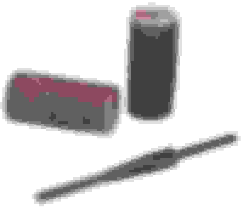
I was going to use my pneumatic die grinders but found some 1/8" burrs that would allow more delicate material removal using a Dremel at lower speed. The burrs on the right are good for hogging out aluminum and the ones on the left are more for steel.
Took my time and got it close with the burrs.
I was going to finish it off with abrasive rolls on the pneumatic die grinder but Eastwood sells a Dremel size mandrel so I can control the speed better. Need to remember to use Grinder's Grease on the spinning stuff.
I was concerned about the holes in the bottom of the manifold. I assume they are to draw off any fuel or oil that ends up in the manifold and the wall in front of those holes (visible in the first photo) served some purpose to help that process. Then I saw a photo of the ported stock manifold in the video and those holes are visible like mine. I'll still have to use the pneumatic die grinder to get to the back of the manifold but this will allow me to smooth the bores up front.
Not sure this modification is going to have a huge payback but for the money it seemed like a good gamble.


 06-16-2020, 06:16 PM