Flow and tuning considerations for L98 MAF Units
 03-31-2011, 08:40 PM
#1
Race Director

Thread Starter

This thread is a consolidation of recent posts addressing MAF flow and tuning considerations for people with moderate-to-wild builds. I believe there is a benefit to this consolidation as I've yet to see this subject breached in the CF before.
The first thing everyone wants to know is what do stock MAF units flow? Please click on this link to see university measurements for intake-tract-related elements.....
http://dtcc.cz28.com/flow/index.htm
But here is where the conversation gets more interesting.....
"My 383 HSR motor peaked the MAF at 4500-4800 rpm. It read 255 and stopped reading. BUT i made 400whp at 6300 rpm and pulled to 6600 without falling off. 4500 rpm is about where I peaked torque. It was flat from 4000-almost 5000
So the 3" MAF was not a restriction. I changed to a 3.5" setup and it did not help power from what I could see at the track."
The first thing everyone wants to know is what do stock MAF units flow? Please click on this link to see university measurements for intake-tract-related elements.....
http://dtcc.cz28.com/flow/index.htm
But here is where the conversation gets more interesting.....
Originally Posted by vetteoz
The misunderstood problem with MAF is not the physical air flow though the sensor but how the '165 ECM " calculates " airflow......
http://www.thirdgen.org/techboard/di...-5000-wot.html
The good news is that both limitations can be easily overcome with minor programming and hardware changes.
All it takes is a MAF with increased measurement range, a larger housing diameter to reduce the air flow restriction, programming changes to rescale the fueling calculation, and the know-how to do so.
The stock MAF will peg around the 280-300 rwhp mark. After this point, PE vs rpm can be used for additional enrichment, but the ECM is blind to the additional airflow.
Easiest way to increase the housing area is to convert to a sensor element that can be easily installed in a larger tube.
Of course, programming changes and a suitable air cleaner will be required.
Originally Posted by GREGGPENN
So, it sounds like programming is more of an issue than flow thru the housing?
Originally Posted by Orr89rocZ
"My 383 HSR motor peaked the MAF at 4500-4800 rpm. It read 255 and stopped reading. BUT i made 400whp at 6300 rpm and pulled to 6600 without falling off. 4500 rpm is about where I peaked torque. It was flat from 4000-almost 5000
So the 3" MAF was not a restriction. I changed to a 3.5" setup and it did not help power from what I could see at the track."
Originally Posted by tequilaboy
The answer [Gregg] is dependent upon flow, rpm and the AFR requirements.
For example, At 4,800 rpm with a pegged MAF, the normal bpw calculation will be limited at an AFR target of 10.19:1 or richer.
For an N/A car, with a relatively lean 13:1 actual AFR, the resulting bpw can support approx. 360-390 rwhp.
For a forced induction car thats happy with an 11.5:1 actual AFR, the same bpw limit can only support approx. 320-345 rwhp.
The situation improves with increased rpm (and gets worse at lower rpm), so the answer will depend upon entirely upon the flow vs rpm characteristics of the engine as well as the need for extra enrichement.
A turbo car, that might peg the MAF as low as 3,200 rpm, and want an 11.5 actual AFR, will be limited for any target AFR richer than stoich. It will be dangerously lean due to the high MAF readings at low rpm. Another method for fuel control is a must.
Most N/A cars can live within these limits when tuned for worst case condtions and run a little rich otherwise. Blower and turbo cars need special attention.
Fortunately, all of these situations can be addressed with the appropriate hardware and tuning methods. No need to compromise.
Originally Posted by USAsOnlyWay
Interesting as always tequilaboy... perhaps I should be planning on trying your MAF solution sooner than later at least for the additional mods coming in the pipeline. At the time after the recent mods the wideband wasn't functioning and thus I have since purchased one but...
My MAF flow begins to flatline at 4,900 RPM, right about 395rwhp and maxing at 403rwhp at 5,300 RPM and staying above 400 from 5k-5.6k. It will be interesting to see what the AFR is with this setup...
These numbers jive pretty well with your comments.
I don't think the flow will necessarily result in more power, as much as accurate fueling would if anything.
Originally Posted by GREGGPENN
Just like any point in the intake system, there is some air resistance. As flow increases, so does that resistance. So, at a certain point, going from a 3" to a larger housing on the MAF will allow more air. If what I'm understanding is correct, a MAF that's too small will result in a couple of things...
Once you pass the 254g/s point (which is the highest measurement in the MAF table), additional flow can't be measured by the MAF/ECM. However, you can see the results on the backside by looking at WB data. As higher amounts of air are "forced" past the upper limit of the MAF, simply add fuel to acheive the desired AFR.
Since the combination of PE by Temp and PE by RPMs could create some very high-percentage increases in fueling, getting enough fuel is not the problem. Getting "enough" air is the potential issue. If the MAF is sufficiently restricting flow in comparison to other parts in the intake tract, you could be losing some power. And, if you don't measure the results with a WB sensor, you're AFR may also be wrong. And, it may be too rich.
Someone let me know if I'm interpreting this wrong.
For me, I looked at the flow data for the TB and the MAF. When the cross-section/flow of the TB is bigger than the MAF, you probably have a restriction. (Or an oversized TB).
I also considered two other things. Since I had an accurate simulation of my combo, it showed air requirements. I was just under the need for needing an upgrade (especially in TB).
I also considered that a V8 motor has 4-cycles. With 8 cylinders and 4-cycles, I presume 2 cylinders must be on the intake stroke at any given time. So, multiply a single runner flow by 2 to see if you're TB is big enough -- and the MAF too. For good measure, add 10-15% to allow for VE above 100. Also, they typically say the intake should flow 15% more than your heads.
Originally Posted by tequilaboy
Getting enough fuel is exactly the problem. Once you go rich enough with the Target AFR, the bpw will be limited within the calculation. This is what limits the power potential of this tuning method.
PE tuning does work to address additional unmetered air, but only to a point. That is what I tried to describe in the earlier post.
Look out for flat pulse widths in your datalogs as rpms increase.
$32 and $32B users can get some relief by using the optional bpw table. This requires a little more tuning effort, but at least offers one solution to the problem.
Originally Posted by GREGGPENN
I haven't figured out how the bpw can be limited "within the calculation". Does this refer to the PE percentage of whatever value it's acheived when the MAF initially hits 254g/sec? IOW, If you're at 80% IDC when the MAF hits max, I guess you can't add 100% PE since you only have 20% headroom, right?
(I'm using IDC vs BPW since it's easier to related to the 100% where the injector goes static.)
(I'm using IDC vs BPW since it's easier to related to the 100% where the injector goes static.)
Originally Posted by tequilaboy
PE tuning does work to address additional unmetered air, but only to a point. That is what I tried to describe in the earlier post.
Look out for flat pulse widths in your datalogs as rpms increase.
$32 and $32B users can get some relief by using the optional bpw table. This requires a little more tuning effort, but at least offers one solution to the problem.
Look out for flat pulse widths in your datalogs as rpms increase.
$32 and $32B users can get some relief by using the optional bpw table. This requires a little more tuning effort, but at least offers one solution to the problem.
Originally Posted by GREGGPENN
I assume that "point" is where the PW causes the injector to go static? Or, can you have flat pulse widths creating say... 70% IDC (as an example). If so, I'm still missing something. (I assume as long as you can add PE and get the IDC to go up, you haven't hit that limit.)
FWIW, I'm hitting 254g/sec on my setup at 4100rpms. At that point, my IDC is about 85%. OTOH, I'm running a modified TPI that probably peaks pretty close to 4100.
To figure my PE above that, I added a percentage for the increase in RPMs (like you described in your attached TGO thread.) But, I also subtracted my estimate for drop in VE as the motor move up BEYOND it's TQ peak. IOW, my increase is almost flat above peak.
Originally Posted by tequilaboy
The limitation that I'm referring to can occur long before the injector goes static and also before you run out of adjustment range in the PE tables. It occurs during the pulse width calculation before the injector constant is considered, when the product of the rpm, flow and AFR target is limited to 65536 due to the 16 bit math.
The larger the injector, the shorter the resulting pw will be when the limitation occurs.
Rough numbers: 24 lb injectors will result in a pw limitation of around 12 ms. 42 lb injectors will result in a pw limitation of around 6.8 ms.
I tried to illustrate in my previous post a couple of examples when this will occur based upon rpm, flow and AFR target.
The point is you can't always achieve the expected enrichment via PE even if you have extra range in the tables and available duty cycle for a given rpm and injector.
Originally Posted by Lemme
Don't understand what you mean by a MAF conversion. Please explain.
Originally Posted by tequilaboy
By MAF conversion, I meant conversion from the factory Bosch MAF to a modern analog MAF in a custom housing. Such a conversion is available from Blowerworks in various configurations.
See GM L98 MAF SENSOR page for details.
http://blowerworks.net/
Note: Keep in mind that the info contained in the link [from TGO] is rather old and somewhat out of date.
At this point in time, I was considering a digital MAF and MAF translator. This approach would require re-pinning the ecm to use the F-MAF input, as well as reconfiguring the bin for the frequency MAF and related tuning.
The analog approach has proven to be much simpler and more flexible without the need for any external translator.
I don't think it is quite 'plug and play'. If the blowerworks maf is scaled to read 500 g/s then the bin has to be changed (the website does say that). Also if one opts for a larger diameter 3.5" or 4" (to address the bottleneck theory) then the air ducting will have to change. All up a pretty expensive mod at about $500 especially if you are not yet making 500 crank horsepower. Having a 600hp c4 is certainly not ruled out though. Supercharger project down the track.
Originally Posted by tequilaboy
The plug and play adaptor that I mentioned is only a jumper harness. It has a 6 pin tyco connector on one end to connect to the new MAF sensor. The other end is a mating connector for the original 5 pin MAF harness-side connector.
This allows you to plug the jumper harness into the original connector and plug in the new sensor without cutting and spicing any wires.
There is also an optional breakout including a 2 pin weatherpack connector which permits use of the sensor's integrated IAT instead of the plenum mounted MAT, if desired. This is intended to mate with the factory 2 pin weatherpack, which is back by the distributor, eliminating the short factory jumper between the harness and the MAT sensor.
The quality of the re-man maf's are not very good, and will have a impact the tune. If you can find a new Bosch maf, the cost is approx. 500. This swap not only can accommodate larger values (of choice for the build) but once completed will also allow for consistency. When needed to be replaced, a new ford/oem maf unit sells for less money (in comparison).....if I had a maf car this is the way I would go.
Tequilaboy, this is going back a couple pages now, but regarding the BW/your MAF do you know if when upgrading the MAF you end up losing resolution by having to change MAF scalars or does the modified BIN actually have hacked programming that allows for additional MAF tables to be added on. As you know, I'm working with a 1986 so $32 mask.
Also, I'm looking for a good datalog for you to use. The ones I have at home on this computer are all in the tuning process and seem to peak the MAF at 247 on that day, though I know with this combo I've flat-lined it at 254 before, which I'd call (perhaps incorrectly?) maxing it out. But I'll try to dig them up, DC was around ~80s, PW around 8-9 as well, so it looks like I have room...though LTermO2 counts are still lean at 138 (like I said, still tuning there) This is with 28 lb/hr LS1 injectors running 58-60psi.
Also, I'm looking for a good datalog for you to use. The ones I have at home on this computer are all in the tuning process and seem to peak the MAF at 247 on that day, though I know with this combo I've flat-lined it at 254 before, which I'd call (perhaps incorrectly?) maxing it out. But I'll try to dig them up, DC was around ~80s, PW around 8-9 as well, so it looks like I have room...though LTermO2 counts are still lean at 138 (like I said, still tuning there) This is with 28 lb/hr LS1 injectors running 58-60psi.
Originally Posted by tequilaboy
Resolution is limited by the 8 bit A/D converter. You have 256 values between 0 and 5.12 volts, or 0.02 volts per step. The change in flow that corresponds to a 0.02 volt step is the effective resolution.
Due to the parabolic nature of a typical MAF transfer function, this resolution is not fixed. Since the transfer function is relatively flat at low voltage, you have high resolution in terms of gm/volt. As the flow increases, the resolution decreases.
As the relationship between flow and voltage is increased to extend range, the resolution is reduced, however the impact is minor.
Lets say you have a MAF that has range for 1,000 hp. At the bottom of the transfer function, a 0.02 volt step will represent around 0.25 gm/sec. At the top of the transfer function, the same 0.02 volt step will represent a flow change of around 8-10 gm/sec.
In any event, the measurement error due to the resolution limitation is relatively small. A couple percent of the total flow.
Keep in mind that the MAF signal is filtered, so the signal will still be smooth between the effective resolution steps and result in smooth fueling.
 03-31-2011, 08:42 PM
#2
Race Director
Thread Starter
Please continue this converstation as you would like. (Credit should go to SlickFX3 for breaching this topic.)
The thing I'm STILL most interested in seeing are the specific elements, units, and formula that overflow the 64k limit mentioned by Tequilaboy. I realize static BPW is a good indicator of trouble, but it would be interesting to have that confirmation (while learning a bit more about the workings of the ODB1 ECM).

gp
The thing I'm STILL most interested in seeing are the specific elements, units, and formula that overflow the 64k limit mentioned by Tequilaboy. I realize static BPW is a good indicator of trouble, but it would be interesting to have that confirmation (while learning a bit more about the workings of the ODB1 ECM).
gp
Last edited by GREGGPENN; 03-31-2011 at 08:54 PM.
03-31-2011, 10:21 PM
#3
Race Director
Thread Starter
BTW...For some of your LT guys with ODB1 computers, I wonder if any of this applies to your cars as well.

04-01-2011, 07:53 AM
#4
Drifting

Member Since: Nov 2009
Location: Perth Western Australia
Posts: 1,340
Likes: 0
Received 2 Likes
on
2 Posts
St. Jude Donor '10

Found this equation on how pulse width (pw) is calculated for an efi controlled engine. May be able to relate it to the c4 ecms calcs
http://en.wikipedia.org/wiki/Fuel_in...h_calculations
pw ms = (air lb/min)/(rpm*strokes per rev*afr*fuel lb/min)*1000*60
Example at idle for 350 ci
air lb/min = 1.03 (approx 8 g/s)
rpm = 700
strokes per rev = 2
afr = 14.73
fuel lb/min = 0.37(22 lb /hr injectors)
Substituting in values gives pw ms = 8.4 ms Actual bpw from datalog = 2.23ms
Example at 5000 rpm for 350 ci
air lb/min = 28.42 (approx 215 g/s)
rpm = 5000
strokes per rev = 2
afr = 14.64
fuel lb/min = 0.37(22 lb /hr injectors)
Substituting in values gives pw ms = 32 ms Actual bpw from datalog = 10.23ms
Interesting that this formula seems to be giving pulse widths 3 times that of my 87! Does the batch fire system fire more than once per cycle?
Last edited by Lemme; 04-03-2011 at 06:42 AM.
04-01-2011, 08:24 AM
#5
Here's another way Gregg. I got rid of the MAF sensor altogether and converted to a MAP sensor system. No more constriction going into the throttle body. Right now I am running a 58mm throttle body being fed air through a 4 inch diameter intake. EFI did the configuring of the ECM for me and with a few pin outs and the addition of a MAP sensor, it was good to go.
Steve
Steve
04-01-2011, 08:56 AM
#6
Pro


Member Since: Mar 1999
Location: Oslo, Norway
Posts: 678
Likes: 0
Received 0 Likes
on
0 Posts

Hi its important to know that whe the throttle is more than 3/4 of full. The O2 sensor is not working and it desengage closed loop. This means that the ECM works after fule and ignition tables and the MAF is not taken into account. Therefor theengine will be stronger even though the MAF is saturated at and earlier rpm than the max
04-01-2011, 03:47 PM
#7
Race Director
Thread Starter
04-01-2011, 03:54 PM
#8
Race Director
Thread Starter
Found this equation on how pw is calculated. May be able to relate it to the c4 ecms calcs
http://en.wikipedia.org/wiki/Fuel_in...h_calculations
http://en.wikipedia.org/wiki/Fuel_in...h_calculations
04-01-2011, 04:05 PM
#9
Race Director
Thread Starter
Hi its important to know that whe the throttle is more than 3/4 of full. The O2 sensor is not working and it desengage closed loop. This means that the ECM works after fule and ignition tables and the MAF is not taken into account. Therefor theengine will be stronger even though the MAF is saturated at and earlier rpm than the max
Even though trims aren't applied in PE mode, I understand the issue to be a matter of overflow for the calculation of PW.
04-01-2011, 05:32 PM
#10
EFI systems has a conversion system to eliminate the MAF sensor altogether. It requires a change of ECM, a cheap MAP sensor, and they program the ECM and supply complete instructions for the pin out. The set up was about $350.
I am now running a super ram, 58 mm throttle body, a new set of AFR 195
heads and a new Comp's cam 229/236 510/510 lsa 113 and a 3.75 rear end. ( probably a bit more lift with the 1.6.1 roller rockers.)
Just finished the final tune yesterday and am heading out to the strip tonight to see how all the new goodies perform.
Steve
04-01-2011, 08:22 PM
#11
Melting Slicks

Here's a plot to illustrate the pw limitation for constant flow of 255 gm/sec assuming a stoich AFR of 14.73:1. This will give you an idea of the excess air that can be supported via PE tuning alone with a pegged MAF at mid-high rpm. Pegging at low-mid rpm is unlikely, but could be a concern for a very large displacement or turbo car.
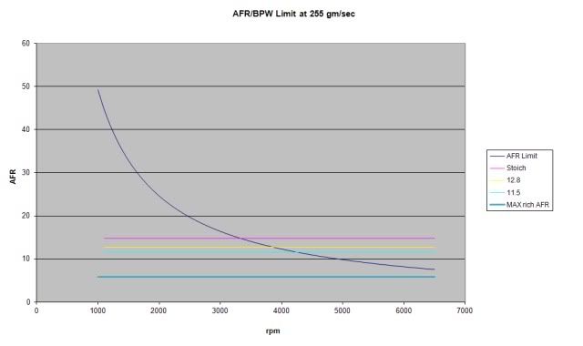
For this condition (pegged MAF for all rpms), AFR targets below (richer than) the dark blue line (or richer than the yellow line below 3800 rpm intersection point) will not result in any additional enrichment, since the pw will be internally limited.
The medium blue line represents the richest AFR target that you can achieve by tuning the PE vs coolant temp and PE vs rpm tables. This is approx. 5.89:1.
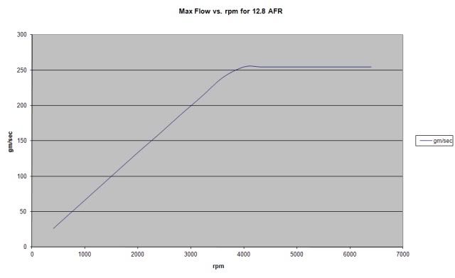
Note: This plot alone doesn't tell the whole story, the pw limitation can also come into play below approx. 4,000 rpm if the MAF flow should exceed the dark blue line of death. This plot is based on a fixed 12.8 target AFR. Richer or leaner targets will skew the resulting curve.
Note: This post is intended to give 86-89 MAF users an idea of what can be achieved via traditional PE tuning methods only. These limitations can be overcome with MAF upgrades and/or special tuning. This does not reflect an overall limitation of a MAF based system.
For this condition (pegged MAF for all rpms), AFR targets below (richer than) the dark blue line (or richer than the yellow line below 3800 rpm intersection point) will not result in any additional enrichment, since the pw will be internally limited.
The medium blue line represents the richest AFR target that you can achieve by tuning the PE vs coolant temp and PE vs rpm tables. This is approx. 5.89:1.
Note: This plot alone doesn't tell the whole story, the pw limitation can also come into play below approx. 4,000 rpm if the MAF flow should exceed the dark blue line of death. This plot is based on a fixed 12.8 target AFR. Richer or leaner targets will skew the resulting curve.
Note: This post is intended to give 86-89 MAF users an idea of what can be achieved via traditional PE tuning methods only. These limitations can be overcome with MAF upgrades and/or special tuning. This does not reflect an overall limitation of a MAF based system.
Last edited by tequilaboy; 04-02-2011 at 06:05 PM.
04-02-2011, 01:17 PM
#12
Melting Slicks
Basic equation that limits the pw calculation (portions borrowed from RBob). Actual 16 x 16 subroutine and useage in code is hard to follow, so we will stick to simplifed decimal values here:
((((983040 / RPM) * (gm_sec * 256) / 512) * AFRTerm) / 256) = 65535 (max)
RPM: actual rpm
gm_sec: actual airflow
AFRTerm: as used in bin, stoich = 445 (6553.6 / AFR = AFRTerm)
Solving for the AFRTerm (Rich Limit Value) gives:
AFRTerm (Rich Limit Value) = 65535/(((983040 / RPM) * (gm_sec * 256) / 512) / 256)
So for a given rpm and flow, the resulting pw will be limited according to the AFRTerm (Rich Limit Value).
The excess air that can be supported (after the MAF is pegged) will be proportional to the AFRTerm (Rich Limit Value)/Actual desired AFRTerm (not the target AFRTerm).
04-02-2011, 05:07 PM
#13
Melting Slicks
Playing around with the math, not convinced the above is completely correct.
The 16 x 16 subroutine returns the upper two bytes of the 32 bit product into the X register, and the middle two bytes of the 32 bit product into the A and B accumulators. The low byte is ignored.
So the product results in 4 bytes: High MiddleHigh MiddleLow Low.
The values in the A and B accumulators are used in the next multiplication operation (effectively dividing the original 32 bit product by 256).
If the MSByte of the 32 bit product is non-zero (greater than 16777215), the A and B registers will be instead filled with FF each. This is where the limitation comes from.
The resultin FF FF will then be divided by 2, leaving 7FFF or 32767 as the max value that can be multiplied by the AFR Term in the next step.
This value will then be multiplied by the AFR term (512 for example) (and again if the product exceeds 16777215 filling the A and B accumulators again with FF FF, respectively). Limitation rears its head again.
So if the MAF * RPM is already limited, the richest AFRTerm can only be 512 or 12.8:1. Hmmm...similar to my line of death plot.
The overall limit equation will be more like AFRTerm (Rich Limit Value) = 16777215/MIN(32767,(983040/RPM)*(MAF*256)/256/2).
Gotta consider how this approach affects the plots...enough for now. Think its the same answer.
Last edited by tequilaboy; 04-02-2011 at 08:14 PM.
04-07-2011, 09:49 AM
#14
Drifting
Member Since: Nov 2009
Location: Perth Western Australia
Posts: 1,340
Likes: 0
Received 2 Likes
on
2 Posts
St. Jude Donor '10
Found this equation on how pulse width (pw) is calculated for an efi controlled engine. May be able to relate it to the c4 ecms calcs
http://en.wikipedia.org/wiki/Fuel_in...h_calculations
pw ms = (air lb/min)/(rpm*strokes per rev*afr*fuel lb/min)*1000*60
Example at idle for 350 ci
air lb/min = 1.03 (approx 8 g/s)
rpm = 700
strokes per rev = 2
afr = 14.73
fuel lb/min = 0.37(22 lb /hr injectors)
Substituting in values gives pw ms = 8.4 ms Actual bpw from datalog = 2.23ms
Example at 5000 rpm for 350 ci
air lb/min = 28.42 (approx 215 g/s)
rpm = 5000
strokes per rev = 2
afr = 14.64
fuel lb/min = 0.37(22 lb /hr injectors)
Substituting in values gives pw ms = 32 ms Actual bpw from datalog = 10.23ms
Interesting that this formula seems to be giving pulse widths 3 times that of my 87! Does the batch fire system fire more than once per cycle?
http://en.wikipedia.org/wiki/Fuel_in...h_calculations
pw ms = (air lb/min)/(rpm*strokes per rev*afr*fuel lb/min)*1000*60
Example at idle for 350 ci
air lb/min = 1.03 (approx 8 g/s)
rpm = 700
strokes per rev = 2
afr = 14.73
fuel lb/min = 0.37(22 lb /hr injectors)
Substituting in values gives pw ms = 8.4 ms Actual bpw from datalog = 2.23ms
Example at 5000 rpm for 350 ci
air lb/min = 28.42 (approx 215 g/s)
rpm = 5000
strokes per rev = 2
afr = 14.64
fuel lb/min = 0.37(22 lb /hr injectors)
Substituting in values gives pw ms = 32 ms Actual bpw from datalog = 10.23ms
Interesting that this formula seems to be giving pulse widths 3 times that of my 87! Does the batch fire system fire more than once per cycle?
04-09-2011, 06:24 PM
#15
Drifting
Member Since: Nov 2009
Location: Perth Western Australia
Posts: 1,340
Likes: 0
Received 2 Likes
on
2 Posts
St. Jude Donor '10
EFI systems has a conversion system to eliminate the MAF sensor altogether. It requires a change of ECM, a cheap MAP sensor, and they program the ECM and supply complete instructions for the pin out. The set up was about $350.
I am now running a super ram, 58 mm throttle body, a new set of AFR 195
heads and a new Comp's cam 229/236 510/510 lsa 113 and a 3.75 rear end. ( probably a bit more lift with the 1.6.1 roller rockers.)
Just finished the final tune yesterday and am heading out to the strip tonight to see how all the new goodies perform.
Steve
I am now running a super ram, 58 mm throttle body, a new set of AFR 195
heads and a new Comp's cam 229/236 510/510 lsa 113 and a 3.75 rear end. ( probably a bit more lift with the 1.6.1 roller rockers.)
Just finished the final tune yesterday and am heading out to the strip tonight to see how all the new goodies perform.
Steve
04-09-2011, 08:06 PM
#16

Playing around with the math, not convinced the above is completely correct.
The 16 x 16 subroutine returns the upper two bytes of the 32 bit product into the X register, and the middle two bytes of the 32 bit product into the A and B accumulators. The low byte is ignored.
So the product results in 4 bytes: High MiddleHigh MiddleLow Low.
The values in the A and B accumulators are used in the next multiplication operation (effectively dividing the original 32 bit product by 256).
If the MSByte of the 32 bit product is non-zero (greater than 16777215), the A and B registers will be instead filled with FF each. This is where the limitation comes from.
The resultin FF FF will then be divided by 2, leaving 7FFF or 32767 as the max value that can be multiplied by the AFR Term in the next step.
This value will then be multiplied by the AFR term (512 for example) (and again if the product exceeds 16777215 filling the A and B accumulators again with FF FF, respectively). Limitation rears its head again.
So if the MAF * RPM is already limited, the richest AFRTerm can only be 512 or 12.8:1. Hmmm...similar to my line of death plot.
The overall limit equation will be more like AFRTerm (Rich Limit Value) = 16777215/MIN(32767,(983040/RPM)*(MAF*256)/256/2).
Gotta consider how this approach affects the plots...enough for now. Think its the same answer.
The 16 x 16 subroutine returns the upper two bytes of the 32 bit product into the X register, and the middle two bytes of the 32 bit product into the A and B accumulators. The low byte is ignored.
So the product results in 4 bytes: High MiddleHigh MiddleLow Low.
The values in the A and B accumulators are used in the next multiplication operation (effectively dividing the original 32 bit product by 256).
If the MSByte of the 32 bit product is non-zero (greater than 16777215), the A and B registers will be instead filled with FF each. This is where the limitation comes from.
The resultin FF FF will then be divided by 2, leaving 7FFF or 32767 as the max value that can be multiplied by the AFR Term in the next step.
This value will then be multiplied by the AFR term (512 for example) (and again if the product exceeds 16777215 filling the A and B accumulators again with FF FF, respectively). Limitation rears its head again.
So if the MAF * RPM is already limited, the richest AFRTerm can only be 512 or 12.8:1. Hmmm...similar to my line of death plot.
The overall limit equation will be more like AFRTerm (Rich Limit Value) = 16777215/MIN(32767,(983040/RPM)*(MAF*256)/256/2).
Gotta consider how this approach affects the plots...enough for now. Think its the same answer.
I took time to read each post in this thread and especially yours.
The calculations GM use are for stock fuel pressure operating range...
Correct?
What happens if you bump up the fuel pressure say to 57 psi to 90 psi?
What happens to the actual AFR then in given operating engine under normal driving or fast driving/ racing loads and at speed?
It was over 6 months ago in C4 scan and tune, "Dr J" made a comment that the AFR in a C4 goes from 14.7 :1 at light throttle operation to 10.0:1 momentarily for so many seconds when the gas pedal is mashed down hard.
It was done intentionally by GM engineers so that the catalytic converter(pre-converters too on 1986 & up c4's) would not overheat suddenly at WOT operation and burn a hole through the C4's fiberglass floorpan.
There must be more than 1 MAF/ fuel trim/ spark calculation tables present?
Is it there in the software and hidden from most C4 tuners other than Dr. J himself ?
Dr. J knew his stuff on C4 hardware and software I recall reading 1st. hand myself.

Last edited by 87 vette 81 big girl; 04-09-2011 at 11:02 PM.
04-09-2011, 09:26 PM
#17
Melting Slicks
What happens if you bump up the fuel pressure say to 57 psi to 90 psi?
The injector will flow more fuel for a given pw, providing enrichement.
A 24 lb injector at 57 pis will flow at a rate of approx. 27.5 lb/hr.
A 24 lb injector at 90 psi will flow at a rate of approx. 34.5 lb/hr.
What happens to the actual AFR then in given operating engine under normal driving or fast driving/ racing loads and at speed?
The extra enrichment will drive the long term fuel trims (BLM) down towards their lower limit of 108 in an attempt to lean things out to return the mixture to the stoichiometric ratio when in closed loop.
During PE mode (70%->WOT), AFR targets will dip into the mid elevens in the vicinity of the torque peak with stock tuning. Extra rich fueling is typically employed for cooling purposes. 11.4 is the richest that I recall seeing in the stock bins.
Increased fuel pressure will still result in extra enrichment in PE mode. The long term fuel trim will be reset to 128 (if previously rich) and the resulting actual AFR will be richer than the target proportional the the new flow rate/old flow rate.
Last edited by tequilaboy; 04-09-2011 at 09:43 PM.
04-09-2011, 09:42 PM
#18
What happens if you bump up the fuel pressure say to 57 psi to 90 psi?
The injector will flow more fuel for a given pw, providing enrichement.
A 24 lb injector at 57 pis will flow at a rate of approx. 27.5 lb/hr.
A 24 lb injector at 90 psi will flow at a rate of approx. 34.5 lb/hr.
What happens to the actual AFR then in given operating engine under normal driving or fast driving/ racing loads and at speed?
The extra enrichment will drive the long term fuel trims (BLM) down towards their lower limit of 108 in an attempt to lean things out to return the mixture to the stoichiometric ratio when in closed loop.
During PE mode (70%->WOT), AFR targets will dip into the mid elevens in the vicinity of the torque peak with stock tuning. Extra rich fueling is typically employed for cooling purposes. 11.4 is the richest that I recall seeing in the stock bins.
He was kind of vague in reference to the the WOT QUENCH that takes place in a C4.
At least with the 1985-1989 Bosch MAF equipped Vettes.
It was a thread started by Lemme / Steve.
Dr.J stepped in with his knowledge and tuning experience.
Dr.J knew his stuff.
04-10-2011, 05:32 AM
#19
Drifting
Member Since: Nov 2009
Location: Perth Western Australia
Posts: 1,340
Likes: 0
Received 2 Likes
on
2 Posts
St. Jude Donor '10
In summary then (in my understanding) the TPI hp limitation caused by the MAF 255 g/s limitation and the fuel injector pulse width limitation (caused by ecm 16 bit math limitations) can be somewhat addressed by raising the fuel pressure and/or installing larger injectors.
04-10-2011, 09:59 AM
#20
For all of us with non engineering backgrounds and race mechanics like myself.
Guys with blowers and Twin Turbo cars maybe can get by with the 86 and up ECM yet and using a "Piggy Back Fuel Injection System".
Like what the 1987- 1991 Callaway TT cars have on them stock.
Plenty of photos published on the internet to see for yourself.
2 separate fuel injectors installed in the air intake tube right before the throttle body opening.
Micro fuel Module or "Brains" hidden behind the passenger side "Breadbox".
Stories, legends, and possibly actual racing facts of the Callaway TT cars running in the deep 10's and high 9's 1/4 mile ET with much of the Callaway TT hardware intact.
Its all buried here on C4 tech history files.
Have to use the SEARCH button to read for yourself.
BR