6.0 LS1 swap in progress
 11-05-2007, 05:48 PM
#1
7th Gear

Thread Starter

Member Since: Mar 2007
Posts: 7
Likes: 0
Received 0 Likes
on
0 Posts
Very close to wrapping up my LS1 swap into my 85 Vette. Let me tell you IT FITS PERFECT!!! Cant wait to go floor this thing and get some tickets! ya!
Im kinda stuck right now though. When I pulled all of the L98 wiring out I really didnt pay attention much and just ripped it out. I took out the engine wiring harness and some of the connectors connected to the engine wiring harness near where the computer is located.
Does anybody know where the main fuse block battery feed wires go through at? and what color are they? I need to find that first so I can find a accesories on wire to power up my new computer and other junk
thank you
pat
 11-06-2007, 04:18 AM
#2


You are a brave man, I wouldn't think of tackling this project without Factory Service Manuals containing the wiring diagrams for both the donor and install vehicles, best of luck.
11-06-2007, 06:05 AM
#3


 11-06-2007, 08:20 PM
#6
Melting Slicks


Orange wires carry the main power to the fuse block. They are typically slightly heavier gauge and splice together at a fusible link near the battery.
You need an on, run ,start power source. W/out a manual or seeing what is left, a test light and some patience are your friend. Remember, you need power in start key position as well. Many accy. available in run are not available in start
The one thing you have going for you is that early C4 body electrical is independant (for the most part) from powertrain electrical
11-06-2007, 10:53 PM
#7
Le Mans Master


Something that is close to being a source of information for you might
be the manual that Painless Performance wrote for installation of their
TBI & TPI wire harnesses.
Although it is for '86 & forward, perhaps you will find nuggets that
move you closer to completion of your project.
.
be the manual that Painless Performance wrote for installation of their
TBI & TPI wire harnesses.
Although it is for '86 & forward, perhaps you will find nuggets that
move you closer to completion of your project.
.
 11-07-2007, 11:38 AM
#9
Former Vendor

Member Since: Jan 2006
Location: Social Circle Georgia
Posts: 698
Likes: 0
Received 0 Likes
on
0 Posts
If you do a search here for LS1 there are a couple threads on the details of it. I do not think it gets involved enough to handle the wiring. You could always go over to ls1tech.com and in the conversions and hybrids section they have wiring info on the engine and PCM in the sticky at the top of the page. That should help you out there. I'd invest in an 85 service manual too.
11-07-2007, 11:55 AM
#10
Le Mans Master
The man asked a straightforward question which none of us has
answered, yet.
If my '89 was close at hand, I would look at the colour & physical routing
of the wires from the junction block below and rearward of the battery
to see what path one or more of these take to pass through the
firewall and connect to the fuse block mounted inside at the base of
the windshield pillar on the passenger side.
I think this is the kind of response that would help the OP.
.
answered, yet.
of the wires from the junction block below and rearward of the battery
to see what path one or more of these take to pass through the
firewall and connect to the fuse block mounted inside at the base of
the windshield pillar on the passenger side.
I think this is the kind of response that would help the OP.
.
11-07-2007, 09:12 PM
#11
Melting Slicks
The man asked a straightforward question which none of us has
answered, yet.
If my '89 was close at hand, I would look at the colour & physical routing
of the wires from the junction block below and rearward of the battery
to see what path one or more of these take to pass through the
firewall and connect to the fuse block mounted inside at the base of
the windshield pillar on the passenger side.
I think this is the kind of response that would help the OP.
.
answered, yet.
If my '89 was close at hand, I would look at the colour & physical routing
of the wires from the junction block below and rearward of the battery
to see what path one or more of these take to pass through the
firewall and connect to the fuse block mounted inside at the base of
the windshield pillar on the passenger side.
I think this is the kind of response that would help the OP.
.
The 85 wires follow that same path as 89. Through the firewall just below and to the left of the brake booster. From there, they run across the firewall to the passenger side fuse block location. As mentioned above Orange is used for main power delivery. Also pink in some instances, but mostly orange
If all of that has been ripped out along with the engine harness...god help him. By that of course I mean Gordon Killebrew
 11-09-2007, 01:56 AM
#13
7th Gear
Thread Starter
Member Since: Mar 2007
Posts: 7
Likes: 0
Received 0 Likes
on
0 Posts
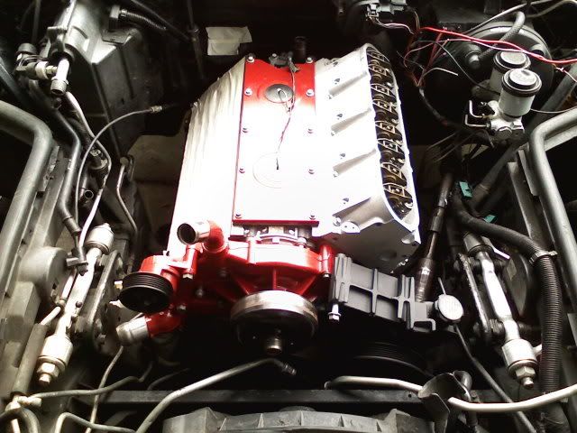
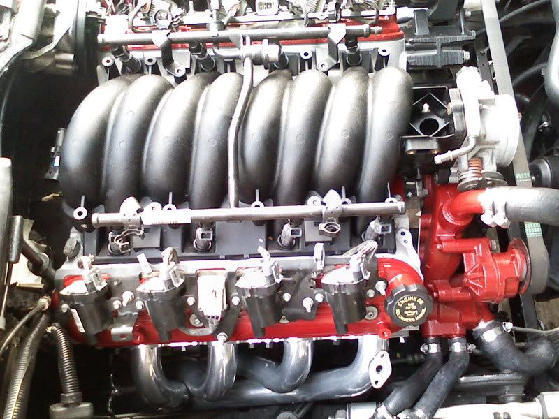
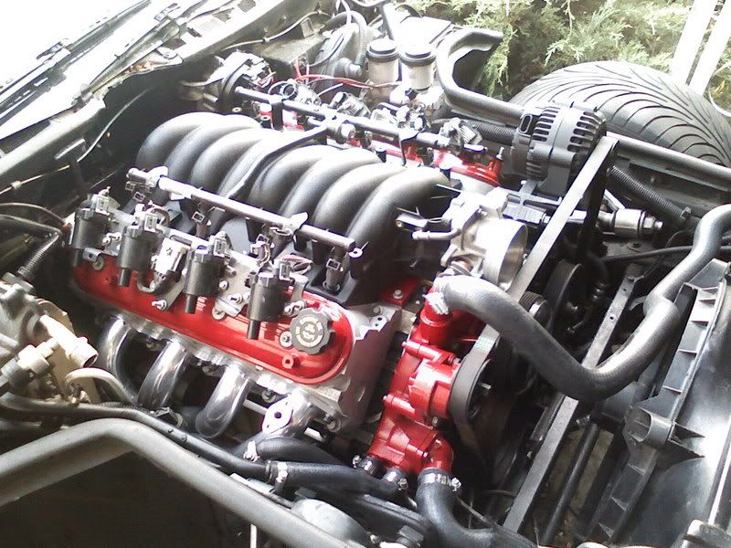
okiee dokiee heres a couple off my phone.
But yes I have found some heavier gauge wires coming from under the passanger side of the dash that I have verified powering up the main fuse block. One was red with a weird lookin inline metal fuse on it and the other one was kind of a faded yellow look to it, almost pale tan. so woohoo! almost there!
As far as the digital dash goes...well lets just say "its NOT" . Im gonna slap some Autometer ultra lights in there. I cant stand the look of the atari dash (good ol 80's eh?) hahahah
im just hoping this damn 700R4 will last for more than a week with 400rwhp...*sigh*
anybody that has a mechanical type mind have no fear! this swap is allot easier than most people try to make it look! that
l
For anybody who is curious, yes im running truck accesories and Mac mid lengh headers. The alt bracket has been modified though. Unmodified the alternator sticks up WAY too high. Also I have chopped off about 2 inches off of the truck oilpan and welded a slab of aluminum on the bottom. T. i am going to be using the stcok truck wiring harnesshe flex plate needs only minor elongating of the holes to bolt right up to the 700R4 torque converter. Im using a 1 inch longer drivshaft yoke and had to weld some aluminum plating to the front section of the trans C-beam to compensate for the engine/trans being roughly 1.5 inches more forward. Im in the process of installing the stock wiring harness as we speak, so ill let you know how that goes.
see ya!
Last edited by camaro6668; 11-09-2007 at 02:06 AM.
11-09-2007, 02:37 AM
#14
Race Director

Member Since: May 2000
Location: No more yankee my wankee, the Donger is tired!
Posts: 17,101
Likes: 0
Received 1 Like
on
1 Post
What's up with the belt routing.
Also you should have used a stright water neck coming out of the water pump. Get it away the from the A arm.
Also you should have used a stright water neck coming out of the water pump. Get it away the from the A arm.
11-09-2007, 11:23 AM
#17
7th Gear
Thread Starter
Member Since: Mar 2007
Posts: 7
Likes: 0
Received 0 Likes
on
0 Posts
heh
guess I should have specificly talked about the pictures...
As far as the belt routing, I was still in process of making a bracket to mount the idler pulley. So now that the idler is installed the belt is allot lower, its still very close to the intake piping but I have about a 1/2 inch clearance so that should be fine.
nope! water pump works ok with LS6 intake, I cut the kickdown bracket of the throttle body off and the neck itself needed a tiny bit of ball peen HAMMER! hahah but ya the heater hoses get pretty close to the a-arm mount but not the a-arm itself. They are at least a inch away from rubbing on any moving parts, they should be just fine.
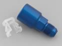
Does anybody know what size the stock inlet and return fuel line fittings are? For the L98 fuel system I mean. Im gonna cut the lines down a bit but plan on using the same fittings.
Where are ya'll buying the ZR1 heater boxes also? Im pretty shure im gonna have to use one with these headers.
yee haw!
guess I should have specificly talked about the pictures...
As far as the belt routing, I was still in process of making a bracket to mount the idler pulley. So now that the idler is installed the belt is allot lower, its still very close to the intake piping but I have about a 1/2 inch clearance so that should be fine.
nope! water pump works ok with LS6 intake, I cut the kickdown bracket of the throttle body off and the neck itself needed a tiny bit of ball peen HAMMER! hahah but ya the heater hoses get pretty close to the a-arm mount but not the a-arm itself. They are at least a inch away from rubbing on any moving parts, they should be just fine.
Does anybody know what size the stock inlet and return fuel line fittings are? For the L98 fuel system I mean. Im gonna cut the lines down a bit but plan on using the same fittings.
Where are ya'll buying the ZR1 heater boxes also? Im pretty shure im gonna have to use one with these headers.
yee haw!
11-09-2007, 12:09 PM
#18
Le Mans Master
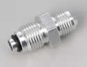
The later L98's use 16mm on both sides.
- 9894DBJERL Earls Fitting, Power Fuel Injection Adapter, -6 AN Hose End to 16mm x 1.5 Female
- 9894DBHERL Earls Fitting, Power Fuel Injection Adapter, -6 AN Hose End to 14mm x 1.5 Female

Compliments: rodj- 9894DBHERL Earls Fitting, Power Fuel Injection Adapter, -6 AN Hose End to 14mm x 1.5 Female
Russell
#648060 (16mm x 1.5)
.
#640860 (14mm x 1.5)
.
.
#640860 (14mm x 1.5)