Supercharging an LT1 Corvette
 11-11-2012, 10:03 PM
#1
Racer

Thread Starter

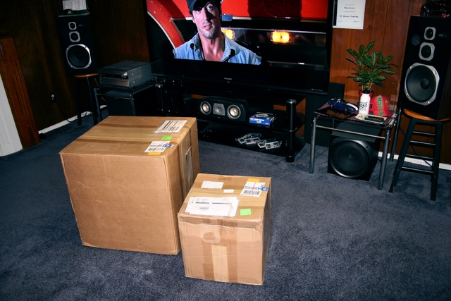
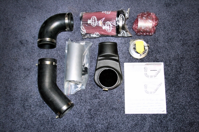
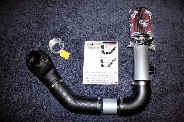
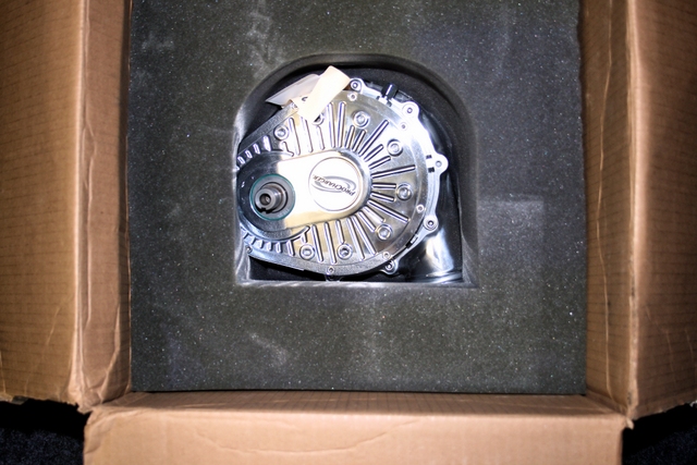
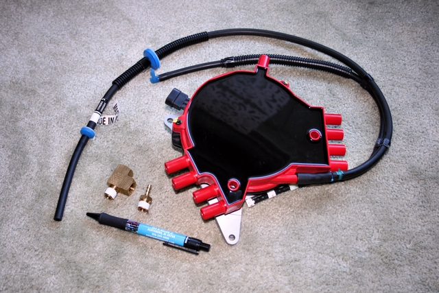
After placing my order back in July, my Supercharger system finally arrived this past week. 
I'd put a lot of thought into which route to take, but ultimately decided to go with the BlowerWorks system over the standard kit from ATI - mostly due to the positive comments I read about the BlowerWorks system here on the forum.
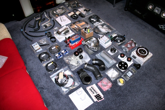
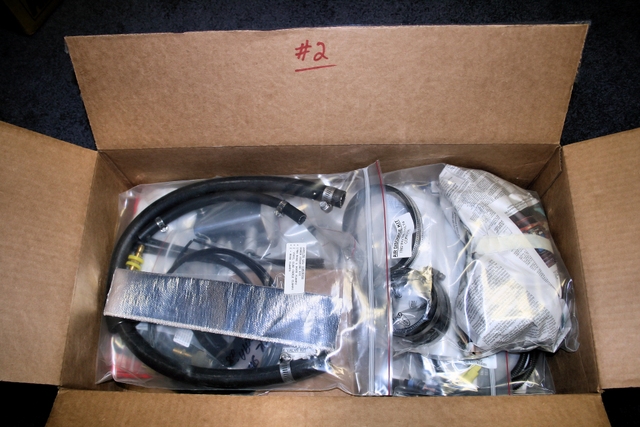
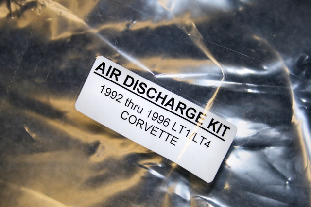
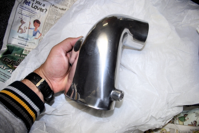
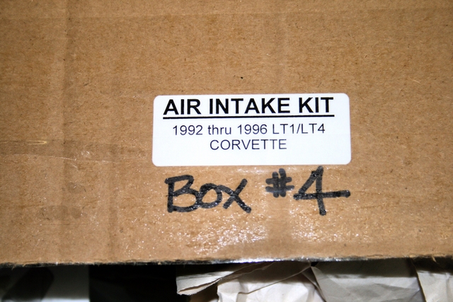
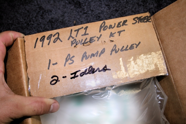
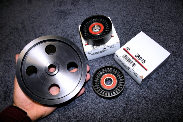
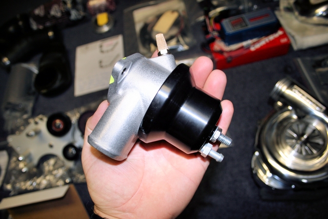
Cost was more than what I originally expected, but over all (at this point anyways) the system certainly looks as if it contains just about every part I need to run it on my '92 - and then some.
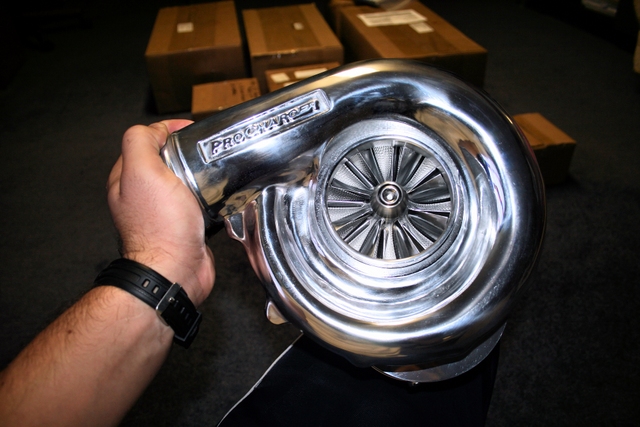
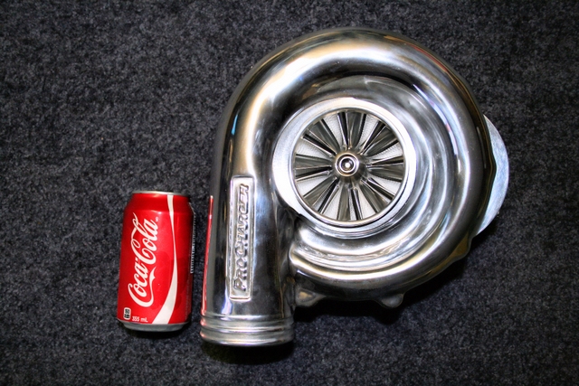
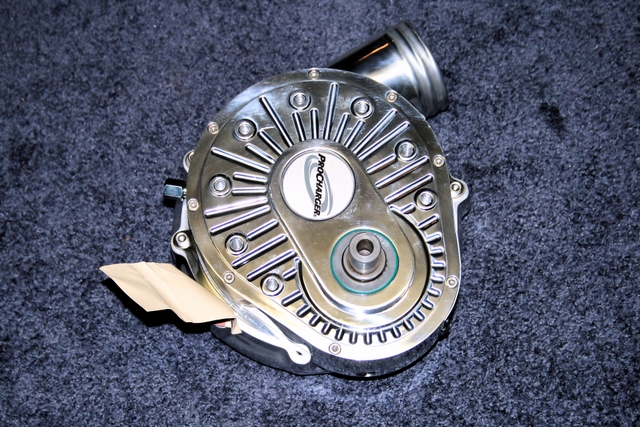
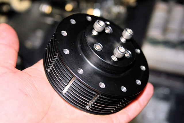
Definitely impressed with what I see so far and man, that D1SC wound up being so much bigger in size than I originally thought.
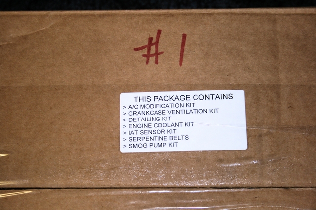
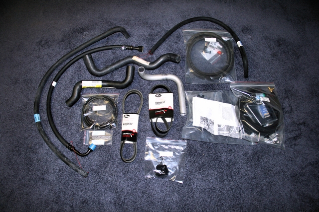
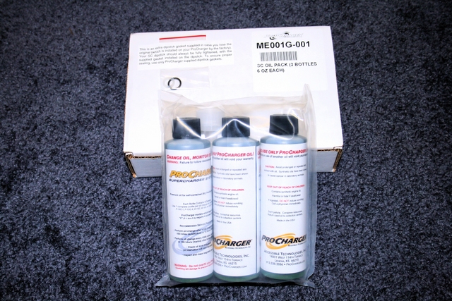
The kit arrived in two box's. The smaller of the two box's contained the Procharger head unit itself. The larger box contained everything else. I must admit, after taking everything out of the box's and laying it across the floor, I was a little taken back by just how many components there are to install. This is definitely NOT going to be a quick and easy, that's for sure. Anybody that says a blower is an afternoon job has never installed one before.
It's going to be a while before I can begin the project due to my schedule over the next month or two, but hopefully I'll at least have Saturday's off to tackle this project a little at a time..... so long as I have the energy for it.
For the time being though, here's a few pictures I took of the contents of the BlowerWorks system.
As I begin the install over the next few weeks, I'll periodically update the thread with further pic's if anybody's interested.
Stay tuned...

 ..
..
 ..
..
 ..
..
 ..
..
 ..
..
 ..
..
 ..
..
 ..
..
..
 ..
..
 ..
..
 ..
..
 ..
..
 ..
..
 ..
..
 ..
..
I'd put a lot of thought into which route to take, but ultimately decided to go with the BlowerWorks system over the standard kit from ATI - mostly due to the positive comments I read about the BlowerWorks system here on the forum.
Cost was more than what I originally expected, but over all (at this point anyways) the system certainly looks as if it contains just about every part I need to run it on my '92 - and then some.
Definitely impressed with what I see so far and man, that D1SC wound up being so much bigger in size than I originally thought.
The kit arrived in two box's. The smaller of the two box's contained the Procharger head unit itself. The larger box contained everything else. I must admit, after taking everything out of the box's and laying it across the floor, I was a little taken back by just how many components there are to install. This is definitely NOT going to be a quick and easy, that's for sure. Anybody that says a blower is an afternoon job has never installed one before.
It's going to be a while before I can begin the project due to my schedule over the next month or two, but hopefully I'll at least have Saturday's off to tackle this project a little at a time..... so long as I have the energy for it.
For the time being though, here's a few pictures I took of the contents of the BlowerWorks system.
As I begin the install over the next few weeks, I'll periodically update the thread with further pic's if anybody's interested.
Stay tuned...
................................
Last edited by LT1*C4; 12-20-2012 at 09:11 PM.
 11-11-2012, 10:03 PM
#2
Racer
Thread Starter
UPDATE: 1
So I was finally able to get some work done on the car this weekend. Not a whole lot, but definitely enough to get the ball rolling.
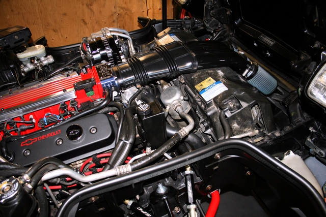
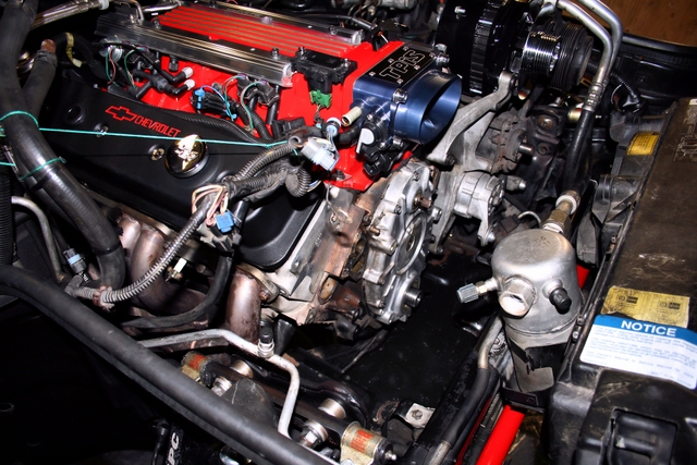
The goal for this first outing was to get the car prepped and ready for the actual install. This involved raising the front end - a project in itself on a lowered 'Vette - - and then clearing up the front of the engine to make space for the new components.
The air intake, water-pump and opti were all removed. As was the hub/ballancer, power-steering pulley and tensioner pulley's.
The power steering reservoir, lines, and A/C accumulator hose were removed as well. That and various cooling lines were also removed.
As expected, the work so far has been more time-consuming than anything else. Nothing overly difficult, just time consuming...
I have a few more parts I need to pick up this week which I figured I'd replace since now would be a good opportunity to change them. Seals for the opti, water pump and crank will be replaced. A new coil will be installed. A pair of breather caps and possibly (haven't decided yet) a new opti.
Next weekend I hope to finally start INSTALLING parts, rather than removing them.
Below are two pictures. What I started off with, and then all the stuff that had to be removed before the new stuff could start to go on. Not bad for a few hours work.
 ..
..
UPDATE 2:
Got to work on the car again this weekend and got some more work done...
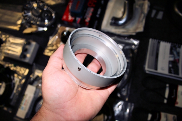
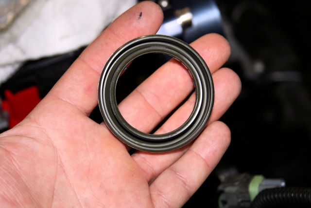
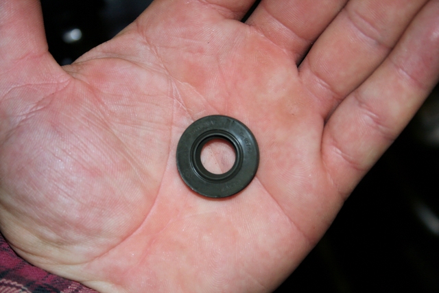
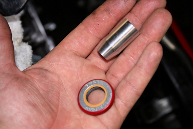
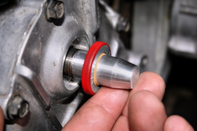
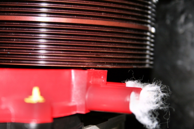
I noticed after removing the stock hub last week that I had a leak from the crank seal. Nothing major but enough get the front of my oil pan all oily. This must have happened recently as my pan was dry the last time I had the car up. I ended up not just replacing the crank seal, but the water pump and opti seals as well. The opti and crank seals were easy enough to install but the water-pump seal required a special tool to help slide the the seal into place and seal correctly. The little aluminum cylinder you see in the picture below, is that "special" tool.
It's a simple yet effective deign. Slide the water pump seal over the cylinder. Slide the cylinder over the splined shaft that sticks out through the timing cover and then push the seal into the opening. Pull out the cylinder and drive in the seal with a soft mallet and socket.
 ..
..
 ..
..
--------
--------
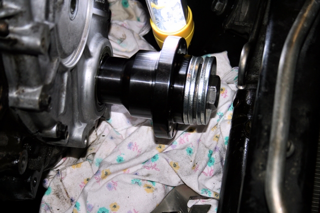
After the seals were all replaced, it was onto the hub. What a nerve racking experience that was!
I was having to put a huge amount of force on the wrench trying to press-fit that puppy on there and each and every time I applied force to the wrench I was terrified I was either going to strip the threads on the rod (the one that screws into the crank) or worse yet, snap the rod inside the crank itself (which of coarse would require the engine to be removed). Amazingly, the threads stayed intact and after the hub was on about half way, it suddenly became easier to turn the wrench. The second half required only half the effort for the hub to press on. That's when I knew the end was in sight and the hub was nearly there.
What a relief when I finally seated the hub...
The Kent Moore hub installer I purchased was obviously designed with the stock hub in mind and not an aftermarket one like the ATI. The new hub is much longer in length and the problem I had was that the "forcing nut" would bottom out on the threaded rod (the one that fits into the crank) right at the point where the threading stopped. This wouldn't allow me to press-fit the hub any further in since I couldn't tighten the nut any more. To remedy this, I ended up finding a place that sells industrial washers with a 1" ID & 2" OD.
I slid 4 of these thick washers over the forcing nut. Now, rather than applying force to the inside of the hub, I was now applying force to the outside of the hub (the washers sat up against the face of the hub).
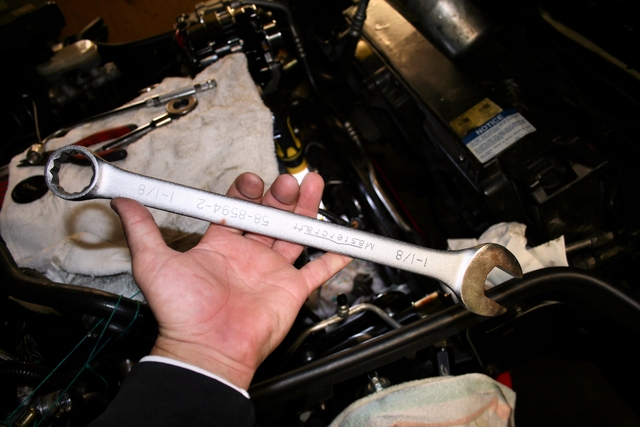
A simple enough fix, but boy was it hard finding washers with those dimensions. Here's some pic's of the big @ss wrench needed to tighten the forcing nut and another showing the extra thick washers I had to use to keep the nut from bottoming out on the threaded rod sitting in the crank.
 ..
..
--------
--------
Once the hub was installed, I decided to install the opti next. While there wasn't anything wrong with the opti-spark I'd installed a few years back, I took the opportunity to just go ahead and replace it anyway since it was already out. I figured I'd keep it as a spare just in case...
As a replacement, I purchased a Petris Enterprises opti. Heard a lot of good things about them and figured this was my chance to try them out. It has the "upgraded" vented design and comes with all the necessary fittings and hoses to make it a bolt-in upgrade. The cool red casing is just an added bonus and not the reason why I bought it...I swear
Still waiting on the harness though, it was shipped in November but still hasn't arrived. Hopefully it'll show up this week. Great looking piece and hopefully it will perform as good as it looks.
 ..
..
 ..
..
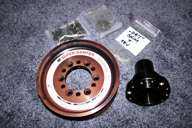
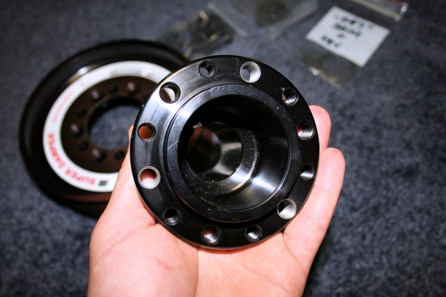
Here's a shot of the new Petris opti and below it, the new ATI hub:
--------
--------
The next step was to install the balancer and that turned out to be a pain in the butt. There's no way of installing it without disconnecting the steering rack and pushing it out of the way for the needed clearance. All the lines going to the rack had to be disconnected. The strap on the passenger side had to be removed. The long bolt that goes through the frame on the drivers side. etc. etc. - all had to be removed. Basically, EVERYTHING had to be removed in order to push the rack out of the way just enough to slide the balancer into place.
It wasn't terribly difficult, but was definitely time consuming.
Here's a shot of the balancer in place and another showing just how tight the clearance is between the balancer and the opti spark. The balancer bolts are only hand tight in this shot. I hope when I finally tighten them all the way once I get my torx bit set later this week, that the balancer doesn't move any further in or it will rub....
 ..
..
--------
--------
Next part of the project was to go back to a "mechanical" style water pump. I ran a Meziere electric water pump originally but Greg at Blowerworks felt it was best to go back to mechanical, since he says it does a much better job at cooling at higher rpms than an electric. I'm taking his word for it, but I'm not thrilled at the idea of going back to mechanical due to it's crappy cooling capability at lower rpm's (where the electric really excelled at). I've got a feeling that cruise-temperatures are going to go back up again and require me to go with a bigger radiator to try and bring temperatures back down, but for now, we'll see.
The first pump I purchased was a "high-flow" pump by "Tuff Stuff" performance. Decent looking piece but the real issue was that the casting was slightly larger than stock. When I test-fitted the supercharger bracket to the motor, then tried the "Tuff Stuff" pump, it interfered with the bracket and I couldn't slide the pump all the way so that it was flush with the block. I guess I could always machine the part of the pump that interfered, but I don't have the resources to do so. It would be easier just to buy a stock GM pump instead, which is what I did.
Found a GM dealer on FleaBay with a stock of 4 (NEW) late-model pumps for just $145 a unit. Score!!! (I should have bought the other 3 for that price, now that I think about it)
 ..
..
--------
--------
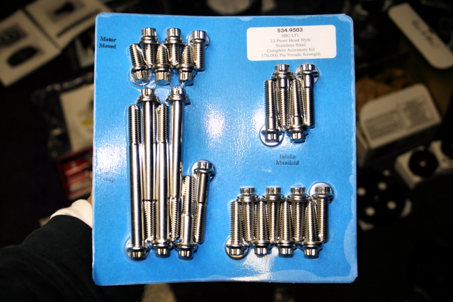
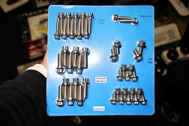
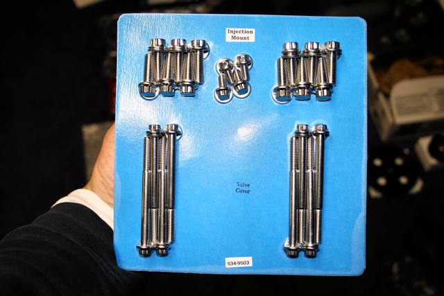
Next was upgrading the fasteners. Picked up an ARP LT1 kit. Ridiculously priced yes, but damn are those 12 point polished bolts oh so pretty to look at.
 ..
..
 ..
..
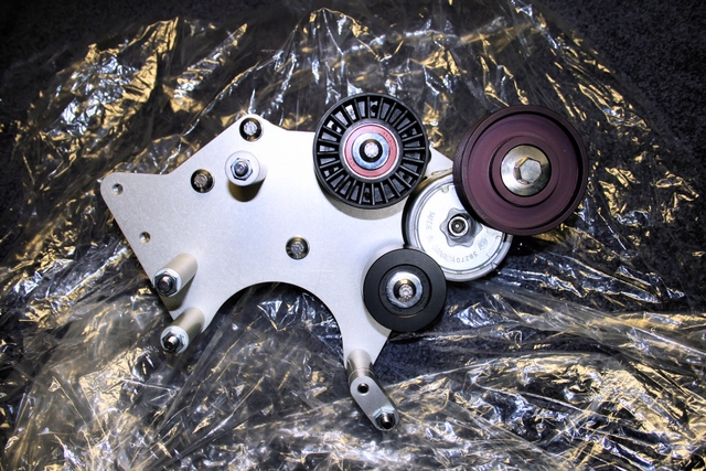
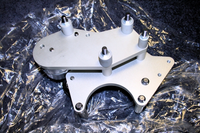
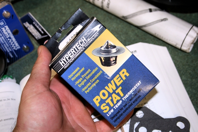
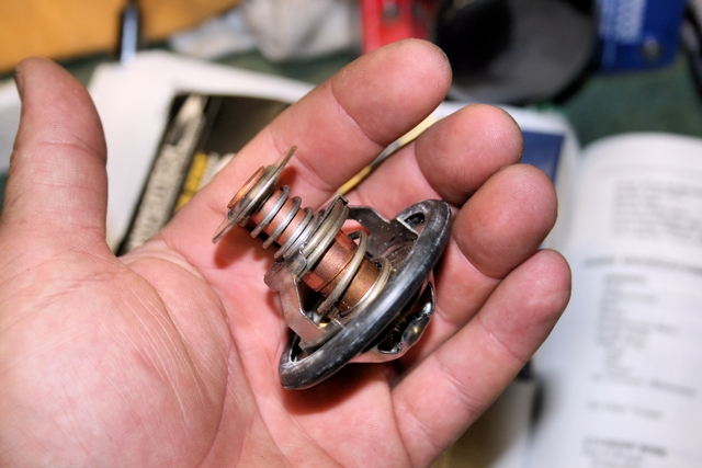
There are a few more things I'm waiting on before I can continue. One is a new Torx bit set. Reason being, I found out that my new ATI balancer uses some fancy T-"plus" sizing which I don't own any of. A new thermostat housing should be here shortly. The new Petris harness for my opti that I mentioned earlier, and a spacer/washer kit from BlowerWorks which I'll need since the bracket bolts I have now are ever-so-slightly too long and are bottoming out on the heads before fully tightening the bracket.
Stay tuned...
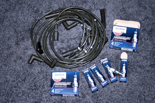
Next weekend I hope to figure out the A/C condenser situation, run the new power-steering lines. Install the new P/S and tensioner pullies. Throw in the new plugs and run the new ignition wires and hopefully have time to install the water-pump.
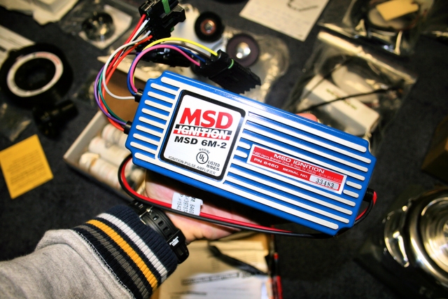
From there it's just installing the supercharger bracket and then the supercharger. Then it's just misc. stuff like the MSD box and in-line fuel pump and then final tuning...
So I was finally able to get some work done on the car this weekend. Not a whole lot, but definitely enough to get the ball rolling.
The goal for this first outing was to get the car prepped and ready for the actual install. This involved raising the front end - a project in itself on a lowered 'Vette -
- and then clearing up the front of the engine to make space for the new components.The air intake, water-pump and opti were all removed. As was the hub/ballancer, power-steering pulley and tensioner pulley's.
The power steering reservoir, lines, and A/C accumulator hose were removed as well. That and various cooling lines were also removed.
As expected, the work so far has been more time-consuming than anything else. Nothing overly difficult, just time consuming...
I have a few more parts I need to pick up this week which I figured I'd replace since now would be a good opportunity to change them. Seals for the opti, water pump and crank will be replaced. A new coil will be installed. A pair of breather caps and possibly (haven't decided yet) a new opti.
Next weekend I hope to finally start INSTALLING parts, rather than removing them.
Below are two pictures. What I started off with, and then all the stuff that had to be removed before the new stuff could start to go on. Not bad for a few hours work.
..UPDATE 2:
Got to work on the car again this weekend and got some more work done...
I noticed after removing the stock hub last week that I had a leak from the crank seal. Nothing major but enough get the front of my oil pan all oily. This must have happened recently as my pan was dry the last time I had the car up. I ended up not just replacing the crank seal, but the water pump and opti seals as well. The opti and crank seals were easy enough to install but the water-pump seal required a special tool to help slide the the seal into place and seal correctly. The little aluminum cylinder you see in the picture below, is that "special" tool.
It's a simple yet effective deign. Slide the water pump seal over the cylinder. Slide the cylinder over the splined shaft that sticks out through the timing cover and then push the seal into the opening. Pull out the cylinder and drive in the seal with a soft mallet and socket.
....--------
--------
After the seals were all replaced, it was onto the hub. What a nerve racking experience that was!
I was having to put a huge amount of force on the wrench trying to press-fit that puppy on there and each and every time I applied force to the wrench I was terrified I was either going to strip the threads on the rod (the one that screws into the crank) or worse yet, snap the rod inside the crank itself (which of coarse would require the engine to be removed). Amazingly, the threads stayed intact and after the hub was on about half way, it suddenly became easier to turn the wrench. The second half required only half the effort for the hub to press on. That's when I knew the end was in sight and the hub was nearly there.
What a relief when I finally seated the hub...
The Kent Moore hub installer I purchased was obviously designed with the stock hub in mind and not an aftermarket one like the ATI. The new hub is much longer in length and the problem I had was that the "forcing nut" would bottom out on the threaded rod (the one that fits into the crank) right at the point where the threading stopped. This wouldn't allow me to press-fit the hub any further in since I couldn't tighten the nut any more. To remedy this, I ended up finding a place that sells industrial washers with a 1" ID & 2" OD.
I slid 4 of these thick washers over the forcing nut. Now, rather than applying force to the inside of the hub, I was now applying force to the outside of the hub (the washers sat up against the face of the hub).
A simple enough fix, but boy was it hard finding washers with those dimensions. Here's some pic's of the big @ss wrench needed to tighten the forcing nut and another showing the extra thick washers I had to use to keep the nut from bottoming out on the threaded rod sitting in the crank.
..--------
--------
Once the hub was installed, I decided to install the opti next. While there wasn't anything wrong with the opti-spark I'd installed a few years back, I took the opportunity to just go ahead and replace it anyway since it was already out. I figured I'd keep it as a spare just in case...
As a replacement, I purchased a Petris Enterprises opti. Heard a lot of good things about them and figured this was my chance to try them out. It has the "upgraded" vented design and comes with all the necessary fittings and hoses to make it a bolt-in upgrade. The cool red casing is just an added bonus and not the reason why I bought it...I swear
Still waiting on the harness though, it was shipped in November but still hasn't arrived. Hopefully it'll show up this week. Great looking piece and hopefully it will perform as good as it looks.
....Here's a shot of the new Petris opti and below it, the new ATI hub:
--------
--------
The next step was to install the balancer and that turned out to be a pain in the butt. There's no way of installing it without disconnecting the steering rack and pushing it out of the way for the needed clearance. All the lines going to the rack had to be disconnected. The strap on the passenger side had to be removed. The long bolt that goes through the frame on the drivers side. etc. etc. - all had to be removed. Basically, EVERYTHING had to be removed in order to push the rack out of the way just enough to slide the balancer into place.
It wasn't terribly difficult, but was definitely time consuming.
Here's a shot of the balancer in place and another showing just how tight the clearance is between the balancer and the opti spark. The balancer bolts are only hand tight in this shot. I hope when I finally tighten them all the way once I get my torx bit set later this week, that the balancer doesn't move any further in or it will rub....
..--------
--------
Next part of the project was to go back to a "mechanical" style water pump. I ran a Meziere electric water pump originally but Greg at Blowerworks felt it was best to go back to mechanical, since he says it does a much better job at cooling at higher rpms than an electric. I'm taking his word for it, but I'm not thrilled at the idea of going back to mechanical due to it's crappy cooling capability at lower rpm's (where the electric really excelled at). I've got a feeling that cruise-temperatures are going to go back up again and require me to go with a bigger radiator to try and bring temperatures back down, but for now, we'll see.
The first pump I purchased was a "high-flow" pump by "Tuff Stuff" performance. Decent looking piece but the real issue was that the casting was slightly larger than stock. When I test-fitted the supercharger bracket to the motor, then tried the "Tuff Stuff" pump, it interfered with the bracket and I couldn't slide the pump all the way so that it was flush with the block. I guess I could always machine the part of the pump that interfered, but I don't have the resources to do so. It would be easier just to buy a stock GM pump instead, which is what I did.
Found a GM dealer on FleaBay with a stock of 4 (NEW) late-model pumps for just $145 a unit. Score!!! (I should have bought the other 3 for that price, now that I think about it)
..--------
--------
Next was upgrading the fasteners. Picked up an ARP LT1 kit. Ridiculously priced yes, but damn are those 12 point polished bolts oh so pretty to look at.
....There are a few more things I'm waiting on before I can continue. One is a new Torx bit set. Reason being, I found out that my new ATI balancer uses some fancy T-"plus" sizing which I don't own any of. A new thermostat housing should be here shortly. The new Petris harness for my opti that I mentioned earlier, and a spacer/washer kit from BlowerWorks which I'll need since the bracket bolts I have now are ever-so-slightly too long and are bottoming out on the heads before fully tightening the bracket.
Stay tuned...
Next weekend I hope to figure out the A/C condenser situation, run the new power-steering lines. Install the new P/S and tensioner pullies. Throw in the new plugs and run the new ignition wires and hopefully have time to install the water-pump.
From there it's just installing the supercharger bracket and then the supercharger. Then it's just misc. stuff like the MSD box and in-line fuel pump and then final tuning...
Last edited by LT1*C4; 01-13-2013 at 01:12 PM.
11-12-2012, 01:11 AM
#3
Melting Slicks

 Looks great so many bits and pieces
Looks like it will be a straight forward install, i did my supercharger install myself all i had was the blower and bracket.
Took time to get the bits required to make it all work, that is where it is worth spending the extra cash and go with blower works as they have been there and done that so they supply all you will need.
Just my 2 cents worth, depending on how many miles the engine has done. Any blowby (boost going past rings will force oil out of the dipstick and seals)if required block the pcv, i ended up putting an oil catch can with hoses from an after market oil filler with vent tube.
Now bolt it up and feel the power
11-12-2012, 10:03 AM
#4
Race Director


yes, it definitely looked like it took a little bit of time to put that whole kit together to send to you !
Every piece in there is researched and not 'cheapened up' in any way like the bastardized commercialized kits for the lt1 vette.
I knew if I was ordering the part from greg that it would be top notch quality and not some 'made in china' fitting.
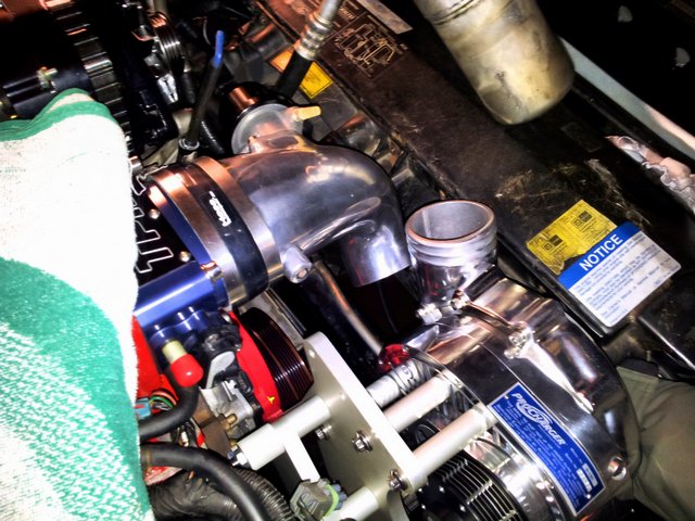
Im assuming you also have the meth/water injection since I didnt see the procharger intercooler in there.
You did it right (vs. buying a 'kit' from someone else and then paying twice to add greg's parts).
Every piece in there is researched and not 'cheapened up' in any way like the bastardized commercialized kits for the lt1 vette.
I knew if I was ordering the part from greg that it would be top notch quality and not some 'made in china' fitting.
Im assuming you also have the meth/water injection since I didnt see the procharger intercooler in there.
You did it right (vs. buying a 'kit' from someone else and then paying twice to add greg's parts).
11-12-2012, 10:07 AM
#5
Race Director
:
Just my 2 cents worth, depending on how many miles the engine has done. Any blowby (boost going past rings will force oil out of the dipstick and seals)if required block the pcv, i ended up putting an oil catch can with hoses from an after market oil filler with vent tube.
Now bolt it up and feel the power
It does catch oil which occurs likely right the instant you let off boost (you cant get blowby oil thru the PCV valve system during boost because of the one-way check valve you install).
If you dont catch the oil it will form some carbon deposits inside your 2 rearmost drivers side cylinders (i know this because I had the heads off). These can increase compression ratio and cause hot spots for detonation to occur at.
11-12-2012, 05:44 PM
#6
Racer

Good choice going with Greg. I'm one of those unfortunate suckers who paid twice, but I've learned a lot and I can say I did it myself. There's nothing wrong with taking your time and doing it right the first time. What sucks is when you put all that in and have to take it out to do internal engine mods. Have fun and don't be afraid to ask questions as there are a bunch of us that have installed these components. What are you doing for fueling and tuning?
11-12-2012, 08:26 PM
#7
Racer
Thread Starter
As far as fuel, I'm already running a Walbro 255lph in-tank fuel pump and Simmons 63# injectors.
I noticed as I was unpacking the contents of the BlowerWorks system on Saturday that one of the cartons contained a Racetronix in-line pump and some sort of upgraded wiring harness. Supplying enough fuel for the engine shouldn't be a problem with the upgrades to the fuel system that have been (and will eventually be) performed.
As for tuning, I purchased a Moats Ostrich 2.0 and some tuning/data logging software through Greg.
11-13-2012, 12:24 AM
#8
Melting Slicks
looks good. just got a box of stuff from gregg myself. ( moats ect.)
That is going to be a nice install, take your time-get pissed with something call it a day and let it rest.
Love all the goodies there. dont forget the spacer behind the Ati dampner hub. Get the correct kent moore tool for pulling and install.
Looks like you have everything!
Im going to look at the pics more and drool $$!
$$!
You got all the good stuff. love that blow off valve (what I have)
Crazy i can identify every piece you have there
That is going to be a nice install, take your time-get pissed with something call it a day and let it rest.
Love all the goodies there. dont forget the spacer behind the Ati dampner hub. Get the correct kent moore tool for pulling and install.
Looks like you have everything!
Im going to look at the pics more and drool
$$!You got all the good stuff. love that blow off valve (what I have)
Crazy i can identify every piece you have there
Last edited by illenema; 11-13-2012 at 12:40 AM.
 12-10-2012, 09:12 PM
#10
Racer
Thread Starter
I've run into a bit of a snag here and hopefully someone can answer this question.
Though I still have a ways to go, this evening I did a mock-up fitting of the blower & bracket to the engine to get an idea of what everything would look like after being installed. That's when I discovered the blower doesn't line up to the aluminum elbow leading to the throttle body.
Unless I've somehow installed the blower incorrectly to the bracket, the blower itself must not be aligned properly for my application. It looks as if the outer casing of the blower isn't set to the right position and needs to be rotated so that it angles down further to line up with the intake elbow.
I've included a picture showing what I mean. It's a bit blurry because it was hard to hold the phone steady with one hand while trying to hold up the heavy bracket/blower assembly up with the other.
So....... Now what?
(EDIT) Issue has been resolved now (see below).
Last edited by LT1*C4; 01-13-2013 at 01:38 PM.
12-10-2012, 10:29 PM
#11
Melting Slicks
Contact gregg. he puts all of these kits together piece by piece,most everything is made to order. he will reply first thing in the morning. Looks great so far. Glad mine is done!
Roasting the *&^% out of the tires BTW
Roasting the *&^% out of the tires BTW
12-10-2012, 10:52 PM
#12
Racer
Thread Starter
I sent him an email a few minutes ago but I think it was for nothing.
I'm pretty sure I just solved the problem.
Checked out the ATI website and read through their literature. One of the "features" listed is the fact that the outer half of ATI's head units are able to rotate 360 degrees to fine tune for proper fitment and alignment depending on application.
Didn't find anything in regards to voiding the warranty so I gave it a try.
I carefully "loosened" the perimeter bolts a tad and sure enough, I could rotate the outer-half of the housing.
The only way to find out the exact position the outer half had to be in, was to go and test-fit the blower/bracket assembly back on the engine.
With the 4 mounting bolts on the bracket lined up to the corresponding points on the cylinder head/block, I was able to get a rough idea where the final position of the blower housing would be and simply rotated the blower housing downward so that it lined up with the intake elbow, then carefully, tightened one of the allen bolts on the blower just to lock the housing in it's new position so I could remove it without it moving around.
Once I pulled the complete assembly out of the engine compartment, I was able to re-tighten the remaining perimeter bolts on the blower and locked the housing in its new position.
Oh, and one thing I noticed, none of the bolts had any loctite on them. Should they?
Thanks for the help people.
Last edited by LT1*C4; 12-20-2012 at 09:15 PM.
12-12-2012, 03:31 PM
#15
Racer
Thread Starter
Nah, I just left them alone and re-tightened the bolts as they came. I was just curious, that's all.
By the end of this weekend I hope to have installed the plugs, ignition wires, waterpump, coolant lines and figured out how to mount the power steering reservoir and A/C conenser. Weekend after that, the blower bracket and finally the blower itself. Things are coming along pretty good.
Last edited by LT1*C4; 12-12-2012 at 08:49 PM.
12-13-2012, 06:55 PM
#16
Intermediate

hey their LTI*C4 so how much did this kit cost and whats the HP? did you need to change the hood? was it an essay install? sorry for all the questions!

 12-23-2012, 12:55 PM
#18
Racer
Thread Starter
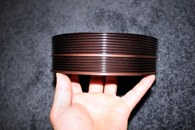
It's because at the time the system was about to be shipped out, the blower pulley size that's normally sent out for a "stockish" LT1 wasn't available. These pullies apparently are custom made and I was told it could end up taking up to 2 extra month's to have one made and then shipped out to me. Since I'd already waited nearly 4 month's by that point, I really didn't feel like waiting another 2.
So, it was agreed that I'd be sent a smaller size pulley (3.75" vs 4" ) which obviously would increase the boost level. The "restrictor plate" was made to try and bring that boost level down a bit.
Greg told me that one of the effects of using a restrictor plate is that it makes the "SET-UP" behave like a positive displacement blower, in other words, LOTS of low end torque while still limiting boost. What the end boost level will be, we don't know yet but in order to keep things safe on the bottom-end, we'll probably be limiting rpm as well (depending on how much boost we see running this pulley).
As long as we don't limit rpm too much - like a 3000rpm redline - I may end up just keeping this pulley and using the restrictor plate. We'll see.
Still have to go out and buy a boost gauge when all is said and done so we can see where the boost level is.
So, it was agreed that I'd be sent a smaller size pulley (3.75" vs 4" ) which obviously would increase the boost level. The "restrictor plate" was made to try and bring that boost level down a bit.
Greg told me that one of the effects of using a restrictor plate is that it makes the "SET-UP" behave like a positive displacement blower, in other words, LOTS of low end torque while still limiting boost. What the end boost level will be, we don't know yet but in order to keep things safe on the bottom-end, we'll probably be limiting rpm as well (depending on how much boost we see running this pulley).
As long as we don't limit rpm too much - like a 3000rpm redline
- I may end up just keeping this pulley and using the restrictor plate. We'll see. Still have to go out and buy a boost gauge when all is said and done so we can see where the boost level is.
Last edited by LT1*C4; 12-23-2012 at 09:16 PM.

