Supercharging an LT1 Corvette
 12-25-2012, 05:35 PM
#21
Racer

Thread Starter

UPDATE 3:
Unfortunately I wasn't able to get as much done this weekend as I'd hoped. As luck would have it, I somehow managed to chew up the threads on the power-steering pump (as well as the threads on my pulley installer tool) during the installation of the power steering pulley. I had to place an order for a new pump as well as a new pulley from BlowerWorks my pulley somehow got damaged during the install as well - you know what they say, when it rains, it pours
The good news is that I had enough time left to install the new water pump, plugs and route the ignition wires into place.
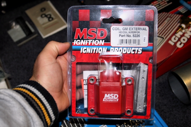
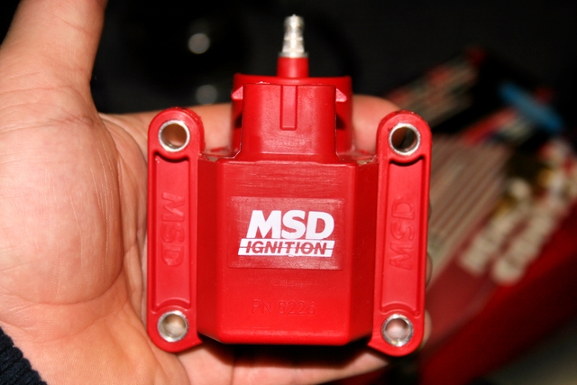
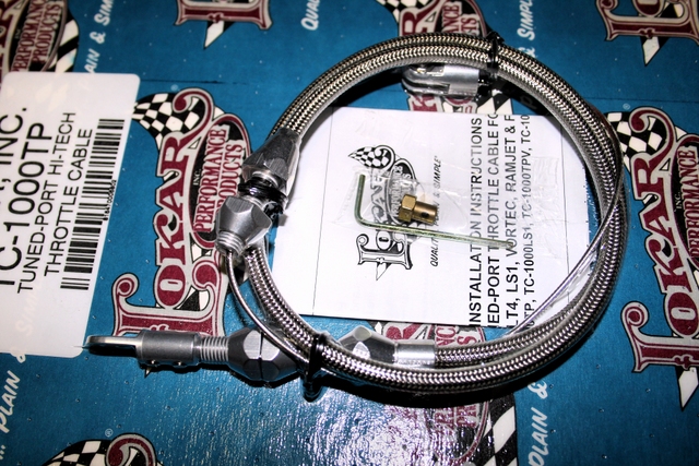
A few minor parts came in this week as well. A new MSD coil and an NOS thermostat housing to replace the old dingy one that was on originally as well as a new throttle cable since I just noticed the plastic retaining clip that hold my current cable has broken off. The braided line on the new Lokar cable matches the fuel lines so it should look pretty sharp once installed.
Next week, I hope to have the new power steering pump and pulley come in so work can continue.
--------
--------
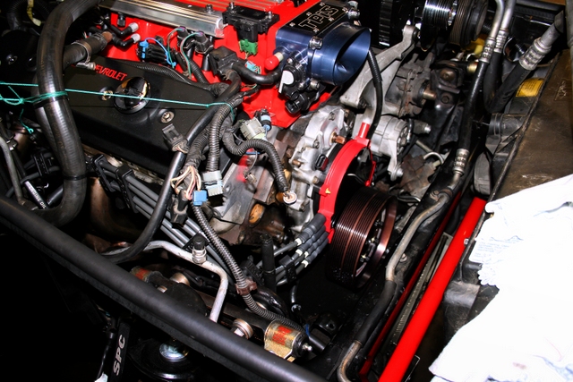
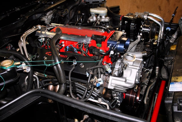
A shot of the new Taylor wires installed and routed the best way I know how. I've yet to find an aftermarket set of LT1 wires that are sized properly. You either get wires that are too long or too short and no matter how you arrange them, you always end up having "slack" on the longer wires so you have to be creative when it comes to routing them. These Taylors are no exception but they are sized better than the MSD's that were on there. I'm re-using the MSD wire looms though and they make a world of difference in terms of keeping the wires nice and neatly arranged.
The second photo shows the new Delco water pump installed. Of coarse, it was only after I tightened all the bolts that I realized I forgot to install the water pump shaft coupling. Grrrr.
 ..
..
--------
--------
The new MSD coil. It's shiny. It's red. It'll match my red intake. Yes, that's why I bought it. Deal with it.
 ..
..
--------
--------
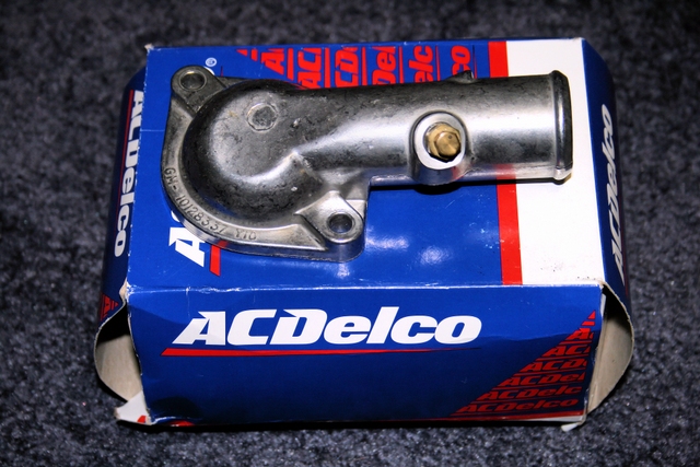
A new thermostat housing and a fancy looking Lokar throttle cable.
 ..
..
UPDATE 4:
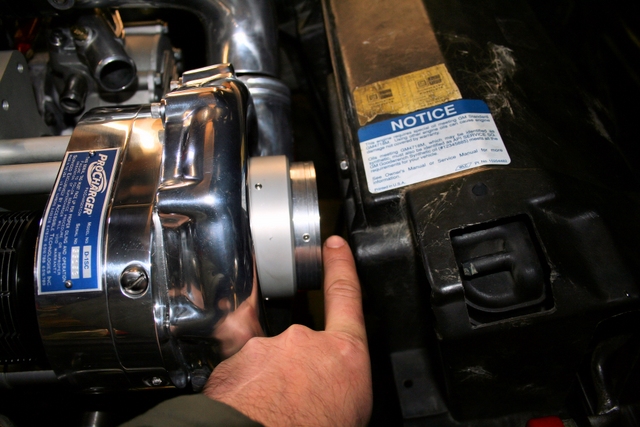
Ran into a bit of a snag this afternoon while test-fitting the blower/bracket assembly.
The blower discharge housing now lines up to the aluminum elbow on the throttle body after having rotated the discharge housing on the blower last week. All is well there.
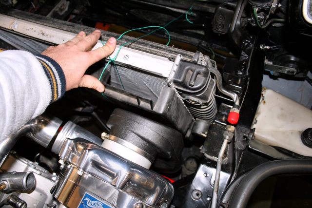
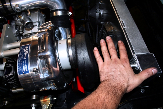
However, the second time I test fitted the blower, I had attached the adapter/restrictor assembly onto the blower inlet. This is when I noticed that there is not enough clearance between the adapter and the radiator shroud to attach the plastic air intake plenum.
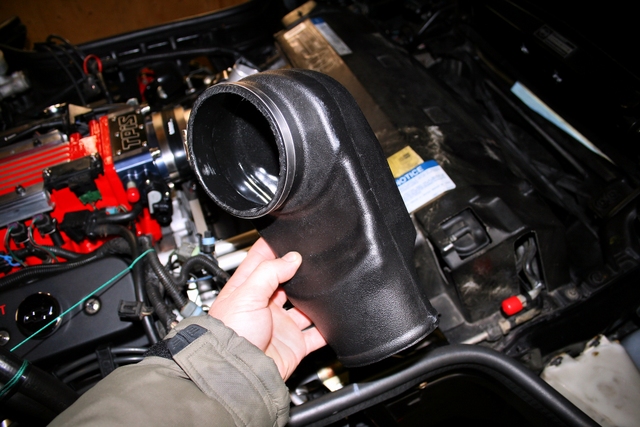
For those wondering what the air plenum is for, it routes straight down into some rubber plumbing and attached to the end of it, is the air cleaner assembly. I wish there was enough space to attach the air cleaner directly to the blower housing, but obviously there isn't. I need the plastic air plenum to route straight down just off the blower and attach my air cleaner assembly from there.
Will update the thread once things have been sorted.
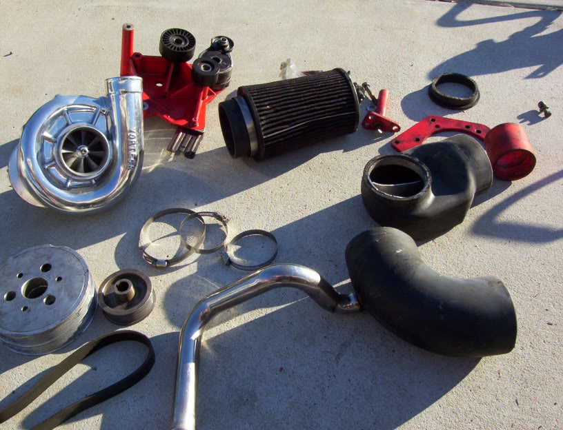
Aside from that, I'm waiting on a new power steering pump and lines (one that goes to the rack and the other, the cooler for the rack). A new water temperature sensor. New idler assembly, and (possibly) a whole new accessory bracket and an A/C delete pulley.
Once that stuff's all in, I can continue.
Stay tuned.
--------
--------
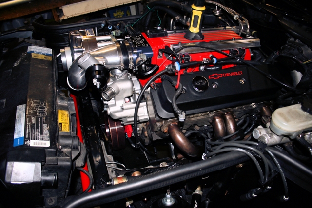
Here's a basic look at what the assembly will look like once fully installed. Looks factory stock don't it?
Note that the blower outlet now lines up with the aluminum elbow coming off the throttle body. Perfect fit now after rotating the discharge housing on the blower unit.
 ..
..
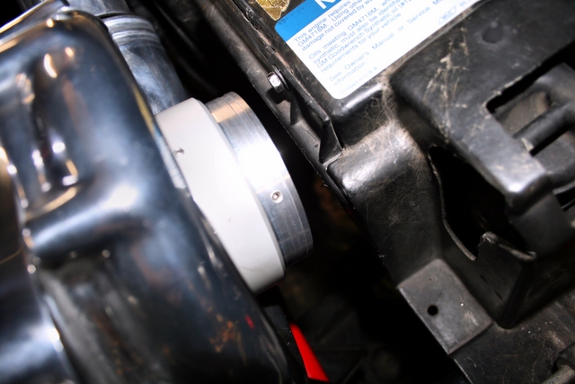
Here you can see a pair of pictures showing the limited clearance I have between the adapter/restrictor plate and the radiator shroud. Just not enough clearance for the plastic air intake plenum to squeeze onto the adapter/restrictor.
 ..
..
--------
--------
Since the freon had already been taken out of the system in order to re-locate the A/C accumulator and run the new (longer) line that came with the kit - I decided I'd make my life easier and unbolt the A/C compressor to make it easier for me to remove my old oil pump in order to replace it and access the oil line that goes to it. Since the freon was already out of the system, it wouldn't hurt to unbolt the compressor.
With the compressor removed, I was amazed at just how much extra space their is under the hood. It's a complete night and day difference. Since the engine bay looked SO much cleaner/less crowded, I' decided that (for at least the first half of the summer anyway) - I'm going to see what it's like without the A/C on the car. I never use it anyway, but have always kept it "just in case".
Since both the compressor and accumulator along with the 2 A/C lines that connect the whole system were all removed as once complete unit, it will only take (literally) 10-15 minutes to re-install them should I choose to throw the A/C back on the car. - So this is more of an "experiment" than anything else. If I don't like it and I feel I need to have the A/C, I'll just bolt back up the compressor and tighten a few lines and she's good to go for new freon.
if I don't miss the A/C- I'll leave it as is. A new A/C delete pulley has been ordered so I'm going to try this out over the upcoming summer and see how I feel about it. The A/C delete pulley is reasonably cheap and since it takes no time at all to re-install what I removed, this little experiment won't cost me much to try out so why the heck not.
For now here's a picture showing just how much space there is on the driver side.
Add to this, the accessory bracket and pullies and you still have a tonne of extra space without the compressor there and even more space in front of the engine just above the frame without the accumulator and lines.
UPDATE 5:
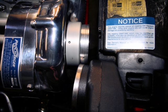
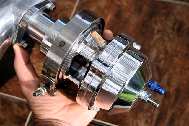
Here's a picture showing the spacer mounted to the blower. You can see I only have about 1" of clearance to the shroud which isn't nearly enough.
The second pic shows the actual intake plenum that needs to fit over the blower.
 ..
..
Any advice or suggestions would be appreciated.
Unfortunately I wasn't able to get as much done this weekend as I'd hoped. As luck would have it, I somehow managed to chew up the threads on the power-steering pump (as well as the threads on my pulley installer tool) during the installation of the power steering pulley. I had to place an order for a new pump as well as a new pulley from BlowerWorks my pulley somehow got damaged during the install as well - you know what they say, when it rains, it pours
The good news is that I had enough time left to install the new water pump, plugs and route the ignition wires into place.
A few minor parts came in this week as well. A new MSD coil and an NOS thermostat housing to replace the old dingy one that was on originally as well as a new throttle cable since I just noticed the plastic retaining clip that hold my current cable has broken off. The braided line on the new Lokar cable matches the fuel lines so it should look pretty sharp once installed.
Next week, I hope to have the new power steering pump and pulley come in so work can continue.
--------
--------
A shot of the new Taylor wires installed and routed the best way I know how. I've yet to find an aftermarket set of LT1 wires that are sized properly. You either get wires that are too long or too short and no matter how you arrange them, you always end up having "slack" on the longer wires so you have to be creative when it comes to routing them. These Taylors are no exception but they are sized better than the MSD's that were on there. I'm re-using the MSD wire looms though and they make a world of difference in terms of keeping the wires nice and neatly arranged.
The second photo shows the new Delco water pump installed. Of coarse, it was only after I tightened all the bolts that I realized I forgot to install the water pump shaft coupling. Grrrr.
..--------
--------
The new MSD coil. It's shiny. It's red. It'll match my red intake. Yes, that's why I bought it. Deal with it.
..--------
--------
A new thermostat housing and a fancy looking Lokar throttle cable.
..UPDATE 4:
Ran into a bit of a snag this afternoon while test-fitting the blower/bracket assembly.
The blower discharge housing now lines up to the aluminum elbow on the throttle body after having rotated the discharge housing on the blower last week. All is well there.
However, the second time I test fitted the blower, I had attached the adapter/restrictor assembly onto the blower inlet. This is when I noticed that there is not enough clearance between the adapter and the radiator shroud to attach the plastic air intake plenum.
For those wondering what the air plenum is for, it routes straight down into some rubber plumbing and attached to the end of it, is the air cleaner assembly. I wish there was enough space to attach the air cleaner directly to the blower housing, but obviously there isn't. I need the plastic air plenum to route straight down just off the blower and attach my air cleaner assembly from there.
Will update the thread once things have been sorted.
Aside from that, I'm waiting on a new power steering pump and lines (one that goes to the rack and the other, the cooler for the rack). A new water temperature sensor. New idler assembly, and (possibly) a whole new accessory bracket and an A/C delete pulley.
Once that stuff's all in, I can continue.
Stay tuned.
--------
--------
Here's a basic look at what the assembly will look like once fully installed. Looks factory stock don't it?
Note that the blower outlet now lines up with the aluminum elbow coming off the throttle body. Perfect fit now after rotating the discharge housing on the blower unit.
..Here you can see a pair of pictures showing the limited clearance I have between the adapter/restrictor plate and the radiator shroud. Just not enough clearance for the plastic air intake plenum to squeeze onto the adapter/restrictor.
..--------
--------
Since the freon had already been taken out of the system in order to re-locate the A/C accumulator and run the new (longer) line that came with the kit - I decided I'd make my life easier and unbolt the A/C compressor to make it easier for me to remove my old oil pump in order to replace it and access the oil line that goes to it. Since the freon was already out of the system, it wouldn't hurt to unbolt the compressor.
With the compressor removed, I was amazed at just how much extra space their is under the hood. It's a complete night and day difference. Since the engine bay looked SO much cleaner/less crowded, I' decided that (for at least the first half of the summer anyway) - I'm going to see what it's like without the A/C on the car. I never use it anyway, but have always kept it "just in case".
Since both the compressor and accumulator along with the 2 A/C lines that connect the whole system were all removed as once complete unit, it will only take (literally) 10-15 minutes to re-install them should I choose to throw the A/C back on the car. - So this is more of an "experiment" than anything else. If I don't like it and I feel I need to have the A/C, I'll just bolt back up the compressor and tighten a few lines and she's good to go for new freon.
if I don't miss the A/C- I'll leave it as is. A new A/C delete pulley has been ordered so I'm going to try this out over the upcoming summer and see how I feel about it. The A/C delete pulley is reasonably cheap and since it takes no time at all to re-install what I removed, this little experiment won't cost me much to try out so why the heck not.
For now here's a picture showing just how much space there is on the driver side.
Add to this, the accessory bracket and pullies and you still have a tonne of extra space without the compressor there and even more space in front of the engine just above the frame without the accumulator and lines.
UPDATE 5:
Here's a picture showing the spacer mounted to the blower. You can see I only have about 1" of clearance to the shroud which isn't nearly enough.
The second pic shows the actual intake plenum that needs to fit over the blower.
..Any advice or suggestions would be appreciated.
Last edited by LT1*C4; 01-13-2013 at 06:32 PM.
 12-26-2012, 12:22 AM
#22
Racer
Thread Starter
Alright, I took off the upper radiator shroud to see if there's anything I can do to push the front shroud forwards enough to gain space for the air plenum to attach to the blower.
With the top shroud removed entirely, I was able to push everything up towards the front of the car a few inches - then I tied everything in place with a piece of string so I could measure how much space I needed for the plenum to fit.
I can see that there's a gap between the front shroud and the radiator. If I were to trim the back of the shroud, I would be able to push it closer to the radiator which would give me a little more clearance.
Below, is a picture showing the areas that I'm considering trimming off the back of the front shroud. I can trim these ares (marked with red/yellow lines) aprox. 1-1.5". This will allow me to push the front shroud closer to the radiator. This will give me an extra 1-1.5" of space. Better, but still not enough.
 ..
..
Here's a pair of close-ups, showing the excess plastic that I'm thinking of removing.
 ..
..
Unfortunately, I noticed I had another clearance issue. I realized that while I had the clearance for the plenum to slide over the blower (as seen in the pic below) the plenum would then interfere with the installation of the 2nd fan assembly. The shroud needs to go forwards at least ANOTHER inch so it won hit the fan. Yikes!
One step up, two steps back.
In other words, when all is said and done, I'm going to have to figure out a way to free up 4-5" to get the space I need for the plenum and 2nd fan assembly - from the factory-stock position.
For the record, I already thought about cutting just the outer portion of the passenger side shroud to make space for the plastic plenum. That wont work either because as I mentioned above,the 2nd fan also interferes with the plenum and obviously can't cut the fan assembly....
Any suggestions?
With the top shroud removed entirely, I was able to push everything up towards the front of the car a few inches - then I tied everything in place with a piece of string so I could measure how much space I needed for the plenum to fit.
I can see that there's a gap between the front shroud and the radiator. If I were to trim the back of the shroud, I would be able to push it closer to the radiator which would give me a little more clearance.
Below, is a picture showing the areas that I'm considering trimming off the back of the front shroud. I can trim these ares (marked with red/yellow lines) aprox. 1-1.5". This will allow me to push the front shroud closer to the radiator. This will give me an extra 1-1.5" of space. Better, but still not enough.
..Here's a pair of close-ups, showing the excess plastic that I'm thinking of removing.
..Unfortunately, I noticed I had another clearance issue. I realized that while I had the clearance for the plenum to slide over the blower (as seen in the pic below) the plenum would then interfere with the installation of the 2nd fan assembly. The shroud needs to go forwards at least ANOTHER inch so it won hit the fan. Yikes!
One step up, two steps back.
In other words, when all is said and done, I'm going to have to figure out a way to free up 4-5" to get the space I need for the plenum and 2nd fan assembly - from the factory-stock position.
For the record, I already thought about cutting just the outer portion of the passenger side shroud to make space for the plastic plenum. That wont work either because as I mentioned above,the 2nd fan also interferes with the plenum and obviously can't cut the fan assembly....
Any suggestions?
Last edited by LT1*C4; 12-26-2012 at 01:41 AM.
12-26-2012, 12:56 PM
#23
Melting Slicks

http://i261.photobucket.com/albums/i...ps2f6e9334.jpg
I have an intake hat bigger then that.
Only way it would fit I cut the shroud and hacked a chunk off 1 fan support leg. Had to modify the trans cooler lines and other goodness, (blowoff line ect) Good luck, This is the fun part.
The shroud is no big deal I just bought a replacement if I ever want to switch it back.
My set up uses 4" silicone elbows and hose
http://i261.photobucket.com/albums/i...ps2f6e9334.jpg
you will wish your rad is about 1" shorter as well
Alright, I took off the upper radiator shroud to see if there's anything I can do to push the front shroud forwards enough to gain space for the air plenum to attach to the blower.
With the top shroud removed entirely, I was able to push everything up towards the front of the car a few inches - then I tied everything in place with a piece of string so I could measure how much space I needed for the plenum to fit.
I can see that there's a gap between the front shroud and the radiator. If I were to trim the back of the shroud, I would be able to push it closer to the radiator which would give me a little more clearance.
Below, is a picture showing the areas that I'm considering trimming off the back of the front shroud. I can trim these ares (marked with red/yellow lines) aprox. 1-1.5". This will allow me to push the front shroud closer to the radiator. This will give me an extra 1-1.5" of space. Better, but still not enough.
 ..
..
Here's a pair of close-ups, showing the excess plastic that I'm thinking of removing.
 ..
..
Unfortunately, I noticed I had another clearance issue. I realized that while I had the clearance for the plenum to slide over the blower (as seen in the pic below) the plenum would then interfere with the installation of the 2nd fan assembly. The shroud needs to go forwards at least ANOTHER inch so it won hit the fan. Yikes!
One step up, two steps back.
In other words, when all is said and done, I'm going to have to figure out a way to free up 4-5" to get the space I need for the plenum and 2nd fan assembly - from the factory-stock position.

For the record, I already thought about cutting just the outer portion of the passenger side shroud to make space for the plastic plenum. That wont work either because as I mentioned above,the 2nd fan also interferes with the plenum and obviously can't cut the fan assembly....
Any suggestions?
With the top shroud removed entirely, I was able to push everything up towards the front of the car a few inches - then I tied everything in place with a piece of string so I could measure how much space I needed for the plenum to fit.
I can see that there's a gap between the front shroud and the radiator. If I were to trim the back of the shroud, I would be able to push it closer to the radiator which would give me a little more clearance.
Below, is a picture showing the areas that I'm considering trimming off the back of the front shroud. I can trim these ares (marked with red/yellow lines) aprox. 1-1.5". This will allow me to push the front shroud closer to the radiator. This will give me an extra 1-1.5" of space. Better, but still not enough.
..Here's a pair of close-ups, showing the excess plastic that I'm thinking of removing.
..Unfortunately, I noticed I had another clearance issue. I realized that while I had the clearance for the plenum to slide over the blower (as seen in the pic below) the plenum would then interfere with the installation of the 2nd fan assembly. The shroud needs to go forwards at least ANOTHER inch so it won hit the fan. Yikes!
One step up, two steps back.
In other words, when all is said and done, I'm going to have to figure out a way to free up 4-5" to get the space I need for the plenum and 2nd fan assembly - from the factory-stock position.
For the record, I already thought about cutting just the outer portion of the passenger side shroud to make space for the plastic plenum. That wont work either because as I mentioned above,the 2nd fan also interferes with the plenum and obviously can't cut the fan assembly....
Any suggestions?
Only way it would fit I cut the shroud and hacked a chunk off 1 fan support leg. Had to modify the trans cooler lines and other goodness, (blowoff line ect) Good luck, This is the fun part.
The shroud is no big deal I just bought a replacement if I ever want to switch it back.
My set up uses 4" silicone elbows and hose
http://i261.photobucket.com/albums/i...ps2f6e9334.jpg
you will wish your rad is about 1" shorter as well
Last edited by illenema; 12-26-2012 at 01:05 PM.
 12-26-2012, 02:52 PM
#25
Melting Slicks
Heres minehttp://i261.photobucket.com/albums/i...lenema/sc2.jpg
There is also a large oil catchcan in there
There is also a large oil catchcan in there
Last edited by illenema; 12-26-2012 at 03:01 PM.
12-26-2012, 04:55 PM
#26
Racer
Thread Starter
I'm really appreciating the input guys. Thanks a bunch. 
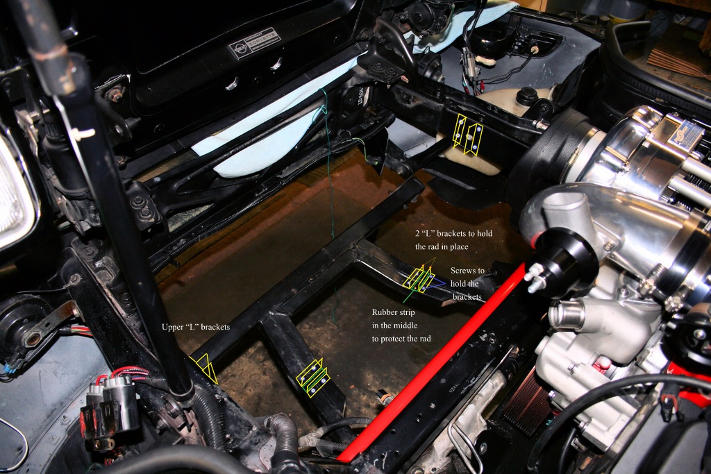
I was looking at the car again today and was curious to see how the radiator, condenser and front shroud were all held in place.
To my surprise, it's only the upper shroud panel that holds everything together. That, and a pair of rubber cushions on the bottom. No actual fasteners of any kind. That surprised me.
What surprised me even more, was what I saw after removing the rad and shroud assemblies.
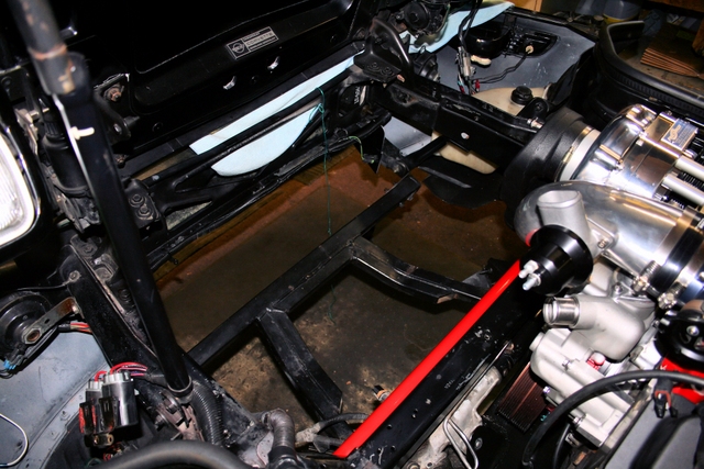
There's a TONNE of space at the front of these cars!!. Literally, about 3 FEET of completely OPEN space !!!
There's nothing there. Nothings in the way. Just a vast amount of open, empty, area. I can't help but wonder why GM put the radiator so damn close to the engine when they had so much space to move it forwards?? Seems like a total waste of space.
I'm wondering why I couldn't just ditch the shroud completely. Mount the radiator as far forwards as it will go (can't go too far forwards or it will interfere with the hood closing if I position the rad up-right). I'd have to fab up some "L" brackets to the existing bottom and side frames but that doesn't seem overly difficult. The upside would be the engine bay area would be MUCH cleaner and MUCH easier to work in.
I'm curious what you all think.
Are there any draw-backs to pushing the radiator further forward? Standing it upright rather then at an angle? Not running a shroud?
Input would be appreciated.
--------
--------
The following picture show just how much empty space there is to work with, once the shroud, radiator and fan assembly is removed. There's literally 3 feet or more of wasted space...
--------
--------
This is where I'm thinking of moving the radiator to. I'll be positioning it upright and further forward. This would give me the clearance I need (and then some) and will also allow much more air flow as well.
Took some quick measurements and the hood still closes with no interference. I have nearly a full inch to spare above the radiator so I'm good there.
 ..
..
--------
--------
Finally, here's a basic idea of what Id like to do. Never mind the Mickey Mouse program I used. It gets the job done.
What do you all think?
If I go this route, I'll have to figure out how I'm going to secure the fans. Since the fan assembly is attached to the shroud and I'll no longer be using the shroud, I'll have to figure out how to secure the fans.
I've been considering purchasing a Dewitts radiator and SPAL fan assembly. I noticed on their websight that they have their fans mounted to the radiator. Can't tell how exactly, but they might be using some sort of bracket on the top/bottom of their radiator and thats where the fans attach to.
If that's the case, I might phone them up and see if they can supply me with a similar set-up. That way I wouldn't have to worry about not having a shroud to hold the fans.
That will just leave the brackets I'll need for the radiator itself.
This might just work...
I was looking at the car again today and was curious to see how the radiator, condenser and front shroud were all held in place.
To my surprise, it's only the upper shroud panel that holds everything together. That, and a pair of rubber cushions on the bottom. No actual fasteners of any kind. That surprised me.
What surprised me even more, was what I saw after removing the rad and shroud assemblies.
There's a TONNE of space at the front of these cars!!. Literally, about 3 FEET of completely OPEN space !!!
There's nothing there. Nothings in the way. Just a vast amount of open, empty, area. I can't help but wonder why GM put the radiator so damn close to the engine when they had so much space to move it forwards?? Seems like a total waste of space.
I'm wondering why I couldn't just ditch the shroud completely. Mount the radiator as far forwards as it will go (can't go too far forwards or it will interfere with the hood closing if I position the rad up-right). I'd have to fab up some "L" brackets to the existing bottom and side frames but that doesn't seem overly difficult. The upside would be the engine bay area would be MUCH cleaner and MUCH easier to work in.
I'm curious what you all think.
Are there any draw-backs to pushing the radiator further forward? Standing it upright rather then at an angle? Not running a shroud?
Input would be appreciated.
--------
--------
The following picture show just how much empty space there is to work with, once the shroud, radiator and fan assembly is removed. There's literally 3 feet or more of wasted space...
--------
--------
This is where I'm thinking of moving the radiator to. I'll be positioning it upright and further forward. This would give me the clearance I need (and then some) and will also allow much more air flow as well.
Took some quick measurements and the hood still closes with no interference. I have nearly a full inch to spare above the radiator so I'm good there.
..--------
--------
Finally, here's a basic idea of what Id like to do. Never mind the Mickey Mouse program I used. It gets the job done.
What do you all think?
If I go this route, I'll have to figure out how I'm going to secure the fans. Since the fan assembly is attached to the shroud and I'll no longer be using the shroud, I'll have to figure out how to secure the fans.
I've been considering purchasing a Dewitts radiator and SPAL fan assembly. I noticed on their websight that they have their fans mounted to the radiator. Can't tell how exactly, but they might be using some sort of bracket on the top/bottom of their radiator and thats where the fans attach to.
If that's the case, I might phone them up and see if they can supply me with a similar set-up. That way I wouldn't have to worry about not having a shroud to hold the fans.
That will just leave the brackets I'll need for the radiator itself.
This might just work...
Last edited by LT1*C4; 12-28-2012 at 08:55 PM.
12-26-2012, 07:22 PM
#27
Melting Slicks
Yes I did something like that, I cut the plastic stops off the bottom of the radiator shroud and moved the radiator forward at more of an angle, but something prevented me from really getting any extra clearance.I forget what it was, like I said a radiator 1" shorter would help one could really angle it better. Almost bought an aluminum radiator that wasn't quite the height of the stock rad.
You should see how close my stuff is, right up against the cross member and resting on the stabilizer bar I think.
I could have ordered a the proper vortech inlet but did not.
You will get it.
You should see how close my stuff is, right up against the cross member and resting on the stabilizer bar I think.
I could have ordered a the proper vortech inlet but did not.
You will get it.
01-09-2013, 10:50 AM
#28
Instructor
This is Great I have a system on mine and anxiously waiting to see how this comes out and numbers! I am planning to update mine with Greg's parts as well. what else did you need to do to put the new ATI pulley on? Estimated Hours? Is it as straight forward in other words as taking the stock off and putting the New one on minus the Steering rack?
01-12-2013, 12:47 AM
#29
Instructor

Member Since: Jul 2009
Posts: 121
Likes: 0
Received 0 Likes
on
0 Posts
I believe your shroud clearance problem is due to that inlet spacer. On my LT1 procharger p1sc I do not have that spacer. Using the plastic inlet clears the shroud.
The trans line needs to be cut but it all fits and I can remove the pastic 90 degree inlet with room to slide forward whenever the blower needs to be removed.
I would think that since the crank pulley has the 8 rib closer to the engine, that ultimately the blower sits closer to the engine with the blowerworks bracket than it does with the procharger bracket.
I would save the headache of cutting anything up and lose that spacer.
Also, I have been told that the procharger plastic inlet is already restrictive, which is not hard to believe by looking how tight the bend is. Someone posted a while back that by fabbing a larger inlet and cutting things up, they picked up over 2 lbs of boost.
So if the spacer is acting like a restrictor plate, your inlet may already be doing at least part of that job and it may not be necessary.
It also looks like you have a larger MAF from you box of goodies pic, and perhaps sticking with stock MAF and screens will also give restriction to limit boost.
Last edited by HighMileage; 01-12-2013 at 12:50 AM.
01-12-2013, 12:59 AM
#30
Instructor
Member Since: Jul 2009
Posts: 121
Likes: 0
Received 0 Likes
on
0 Posts
Greg, I thought the ATI balacer was a hair over 7.5 inches. Can you comment on my advice above? I have been wanting to get your bracket, but do not want to cut the shroud up. Does your bracket and balancer bring the blower closer to the engine than procharger bracket?
01-12-2013, 04:11 PM
#31
Team Owner

Member Since: Mar 2001
Location: Boston, Dallas, Detroit, SoCal, back to Boston MA
Posts: 30,596
Received 238 Likes
on
166 Posts

You need some kind of shroud, at least to the inlet side.
I've seen the radiator laided down.
Plenty of room them.
My inlet is the larger custom unit.
I've seen the radiator laided down.
Plenty of room them.
My inlet is the larger custom unit.
01-12-2013, 08:21 PM
#32
Melting Slicks
Yep looks good. proceed!
Looks to be a bit chilly up there.
Your going to have alot of fun when complete.
That additional power is a lot of fun-and its effortless.
I just had mine out roasting the tires at part throttle
Looks to be a bit chilly up there.
Your going to have alot of fun when complete.
That additional power is a lot of fun-and its effortless.
I just had mine out roasting the tires at part throttle
Last edited by illenema; 01-14-2013 at 03:29 PM.
01-13-2013, 11:08 AM
#33


Hi Guys ! First let me say that Mr. LT1 has been a pleasure to deal with !!! He has been very patient with me and my slow delivery - LOL !
First - the ATI balancer made to my spec has an effective diameter of 7.362". I never count 'lips' if any. Stock GM LTx has an effective diameter of 7.0".
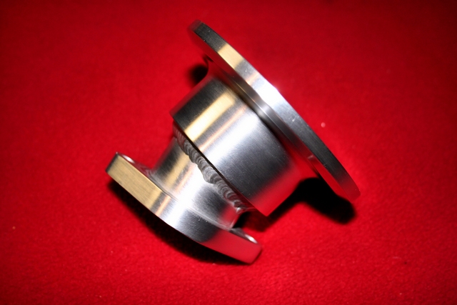
Next let's look at the air inlet pieces. I started supplying the ATI pieces because Vortech discontinued their 'stuff'. The Vortech pieces were 3" od and fit nicely but definitely restrictive. The ATI pieces are 3.5" od and less restrictive but do not fit w/o a lot of work. The reason for the air inlet "extension" piece was/is because my bracket as you all have guessed moves the blower about an inch closer to the engine. So if you started with an ATI kit the extension piece kept all relative dimensions about the same. If you want to lose the extension that's fine. I suppose if max boost were your goal the extension piece less the restrictor might actually help (allows air to straighten a bit).
My original LTx kit (introduced years before Vortech or ATI) uses a CW rotation blower where the air filter hangs over the headers. You can still make max power with this kit !
The Vortech kit (which is no longer available) and the ATI kit use CCW blowers where the air filter sits in the passenger side headlamp cavity.
The reason for my concern over boost levels with LTx's kit is we are not using any water/alcohol injection at this point and the engine is stock.
TBC (to be continued) ! I love LTx's pics - so sweet !
Best regards,
greg
First - the ATI balancer made to my spec has an effective diameter of 7.362". I never count 'lips' if any. Stock GM LTx has an effective diameter of 7.0".
Next let's look at the air inlet pieces. I started supplying the ATI pieces because Vortech discontinued their 'stuff'. The Vortech pieces were 3" od and fit nicely but definitely restrictive. The ATI pieces are 3.5" od and less restrictive but do not fit w/o a lot of work. The reason for the air inlet "extension" piece was/is because my bracket as you all have guessed moves the blower about an inch closer to the engine. So if you started with an ATI kit the extension piece kept all relative dimensions about the same. If you want to lose the extension that's fine. I suppose if max boost were your goal the extension piece less the restrictor might actually help (allows air to straighten a bit).
My original LTx kit (introduced years before Vortech or ATI) uses a CW rotation blower where the air filter hangs over the headers. You can still make max power with this kit !
The Vortech kit (which is no longer available) and the ATI kit use CCW blowers where the air filter sits in the passenger side headlamp cavity.
The reason for my concern over boost levels with LTx's kit is we are not using any water/alcohol injection at this point and the engine is stock.
TBC (to be continued) ! I love LTx's pics - so sweet !
Best regards,
greg

 06-23-2013, 05:28 PM
#38
Racer
Thread Starter
Holy thread revival Batman!!
Yup. Back from the dead. I'm alive and well and so is the car. Well, not quite alive yet (the car that is) but it's getting close...
This little project has turned out into what has to be, the longest supercharger install EVER!!!.
While things have FINALLY started to move along recently - from the get-go, there's been delay after delay.
There have been some items that I literally waited month(s) for and I couldn't continue on without them. Not all were supercharger related components mind you, but there were a number of item's that I wanted to replace since I was already "in there" sort of speak - and figured now was the time to change them.
The biggest problem has been the waiting game. I've spent far more time just waiting for stuff, than actually working on the car itself, hence the reason for little or no progress since my last update.
In addition to waiting for parts, any issues with a part when it finally did arrived (say, it was the wrong part or didn't fit properly or whatever the case may be) that meant I had to send it back for a replacement. That meant shipping the item back to the vendor (1 week minimum delay right there) then wait for the vendor to prepare and ship a replacement part and ship it back out to me (another week again).
In a nut shell, the slightest mix-up with a part or order would add a 2 week delay at the bare minimum. If two parts needed replacement for whatever reason, there's another month of down-time.
The car as of today is about 90% complete, so I figured I'd update on what's arrived. What's changed and what I still have to replace, or am still waiting to arrive.
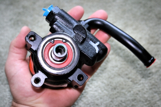
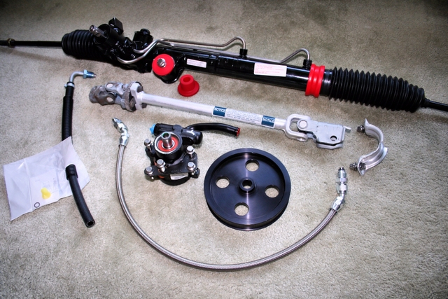
Steering components:
Nothing supercharger related, but something I was kind of forced to deal with. When I originally installed the new aluminium power-steering pulley that came with the BlowerWorks kit, the threads on the power steering pump got damaged during the pulley install and I wasn't able to press-fit the pulley on to the pump all the way.
Unfortunately, the damaged threads not only prevented my from fully installing the pulley, they also meant I was unable to remove the pulley either...
I was left with no choice but to buy a new PS pump - as well as a new pulley. Grrrrrr...
I have a knack of getting carried away when I work on my car and when all is said and done, end up doing more (and spending far more) than originally anticipated. This project was (unfortunately) no different.
The power steering line that goes to the pump was on so tight that I basically rounded off the edges of the nut trying to loosen it, so I just decided just to cut the line off with a Dremel and replace it with a braided line from DRM.
A new AC/Delco pump was ordered and of coarse, since I was also replacing the one line, it didn't make since to leave the others, so I decided to replace all the PS/PS cooler lines while I was at it. With the lines and cooler removed, I had a nice clear view of the factory 21 year old rack and pinion. It still worked just fine, but for how much longer?
Since I was already replacing the pump, pulley, lines and fluid, it didn't make much sense leaving the stock R&P in place. Especially since it was so much easier to get to with all the other components removed.
I went out and ordered a quick-ratio (code NS) z51 rack and pinion and replaced the rubber R&P bushing with poly's. Also ordered some shiny new ARP fasteners to hold it all in place.
Oh, and since everything else in the steering system was about to be replaced, what the heck, may as well install a new intermediate steering shaft while I'm at it.
 ..
..
Accessory bracket :
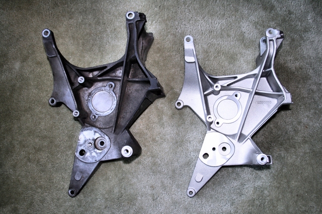
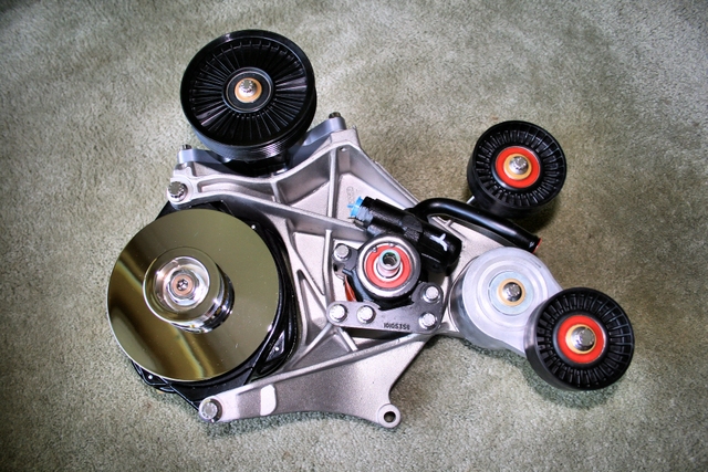
With the accessories all removed, I noticed that the accessory bracket itself was pretty cruddy looking. Not surprising given the fact it's not exactly a part you can reach in order to clean, so there was about 21 years of crap on it.
I decided to pull it out to clean it up and that's when I discovered that the threads that the tensioner and idler pulley bolts screw into were in pretty rough shape, so I began looking to find a replacement bracket. As it turns out, the accessory bracket for the later LT1 cars has been discontinued for quite some time now, so I set off to find a used bracket on FleaBay.
As luck would have it, there was some guy out in Missouri that just happened to have a brand new (NOS) accessory bracket in his possession still in the original sealed box, so I snatched it up. Wasn't cheap, but I prefer to buy new parts whenever I have the option to do so.
Some pics of the new brackt alone and with the accessories attached. I decided to replace all the old fasteners with Stainless ARP fasteners just for the hell of it.
 ..
..
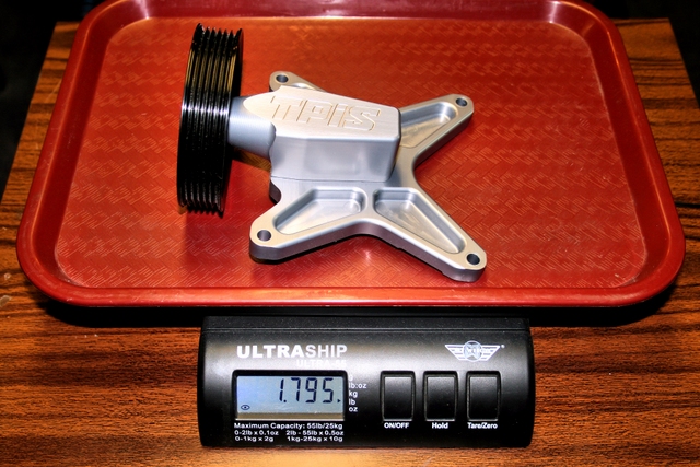
A/C:
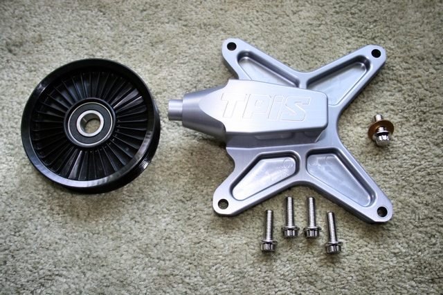
As I mentioned in a previous post, I decided I was going to (temporarily?) try running the car with no A/C and see how it would affect (or wouldn't affect) my day to day driving.
In all the years I've owned this car, I think I may have turned on the A/C twice. Once when I first bought the car (to see if it worked) and maybe 1 other time from that point on. Since the windows are always down and the roof always off whenever I drive this car, I decided to ditch the condensor, accumulator and all related A/C lines in favour of an AC delete bracket from TPIS.
If for whatever reason I decide I want the A/C back, it's just a matter of bolting up the compressor and lines back up which could be done in 20 minutes or less (I took them all out as a complete assembly).
The A/C delete bracket itself is machined from a solid block of billet aluminium, and is an anodized work of art. The amount of space it clears under the hood when replacing the compressor is amazing. A fairly significant amount of weight savings as well...
 ..
..
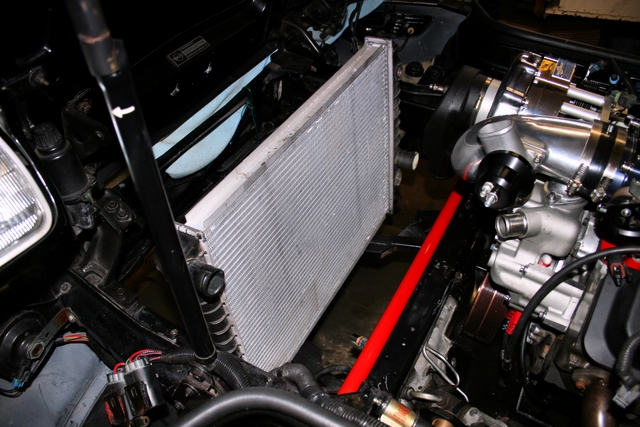
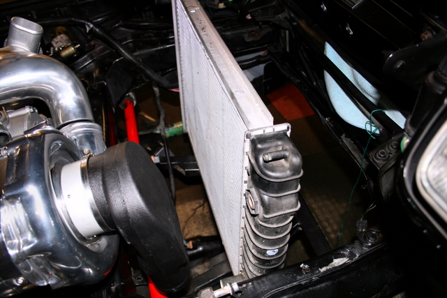
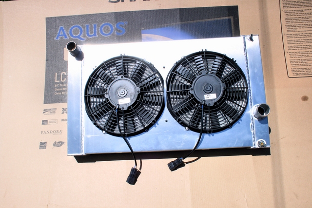
Radiator:
As many of you saw in my older posts in this thread. The factory radiator/shroud assembly had become a major issue with the install. The entire assembly was far too close to the engine and I didn't have enough clearance to fit the intake hat over the supercharger inlet.
Some suggested I cut up the shroud and modify the right-side fan assembly in order to clear the intake hat. I thought about it a bit and eventually came to the conclusion I'd be able to clear up a lot more space if I could somehow find a way to relocate the radiator further forwards. Doing so would not only add clearance, IMO, it would look better than cutting up half the shroud.
This was one of those parts that set the project back a few month's as I was communicating back and forth with one of our forum sponsors (Dewitts) in regards to making a custom radiator for my car.
Eventually, I came up with some measurements and a mounting idea that I sent off to Dewiits to have them make.
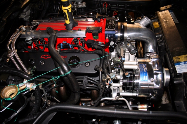
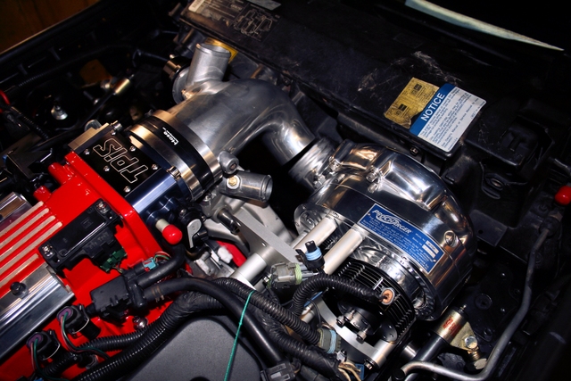
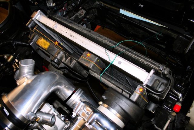
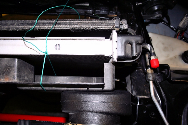
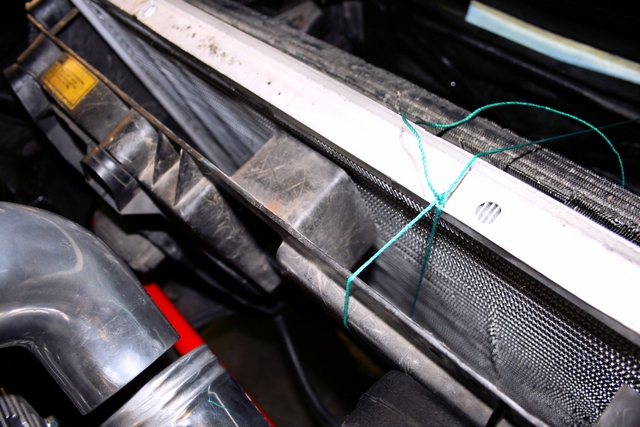
What you see here is the finished product. It took a looooooong time to get, but if this radiator cools as good as it looks, the wait and cost to have it made will have been worth it. Heck, even if it doesn't cool any better than stock, it was worth it just for the fact that I now have tonnes of space in front of the blower. I can run the supplied BlowerWorks intake hat, or just about anything else I want and have room to spare.
Your looking at a 2 core radiator built to the specifications I provided to Dewitts. It's dimensions are both lower and wider than stock. It has mounting tabs located on either side of the end tanks witch allow the radiator to be secured between the cars frame rails through (already existing) openings. It's running a pair of high performance Spal fans enclosed in a custom aluminium shroud.
The depth of the entire assembly is maybe 1/4 that of the factory rad/shroud and overall weight is actually less as well but due to the extra coolant capacity of the larger radiator, total weight might end up being very close between the two. Clearance has increased both in front AND behind the radiator. Pictures tell a thousand words and the following show how GM should have originally designed the rad/shroud assembly on these cars.
It clears up so much extra space, it's like working on a completely different car...
 ..
..
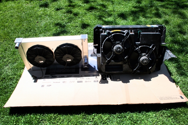 ..
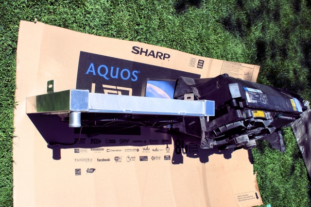
..
Blower inlet clearance: Stock Rad set-up compared to redesign. (Note: I'll no longer be using the "hat" style intake shown below, but a filter right off the blower inlet since I now have the clearance to do so.)
 ..
..
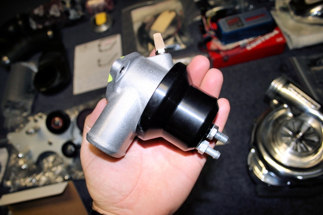
Bypass valve:
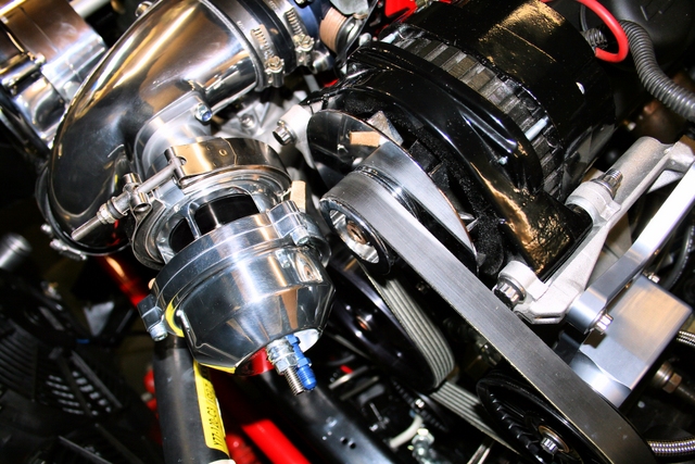
Originally the BlowerWorks system came with the standard Vortech valve. Although I'm sure it would have worked fine. It didn't "LOOK" the part.
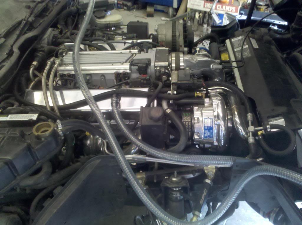
I wanted something that would not only look better, I wanted something that would SOUND the part as well and just as importantly, would not be a restriction later on as engine mods progressed. Enter Vortech's Maxflow BV57. This thing is just MASSIVE!! Never seen another valve this big before on a street car. It's ridiculous. Yes, it's overkill right now, but I have big future plans for the little LT1.
Below is the new BV57 compared to the previous Maxflow Vortech valve:
 ..
..
With the BV57 venting out into the atmosphere, this car's going to sound like a street sweeper. Can't wait.
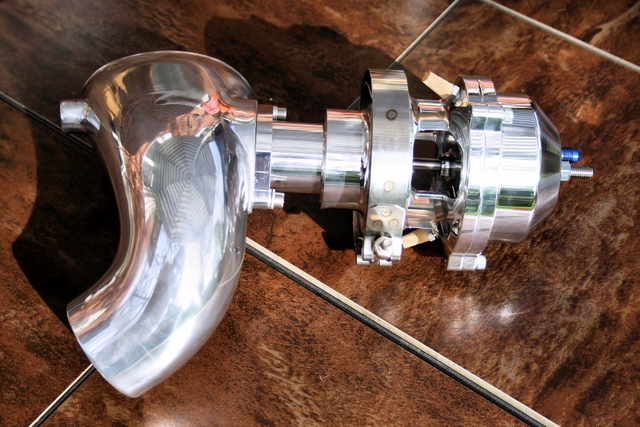
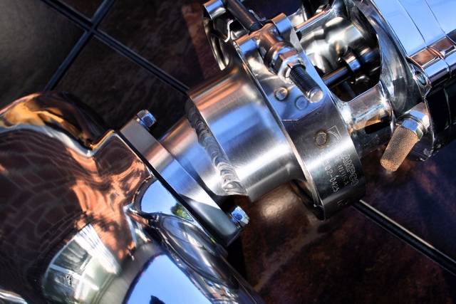
Of coarse, going this route created some new problems. For one, because this valve is not application specific, it requires a flange to be custom made for each individual application. So Greg at BlowerWorks was kind enough to machine a gorgeous looking adapter which would allow me to run the valve on my Vortech air intake. The adapter allowed the valve to mount perfectly.
Unfortunately, I wasn't out of the woods just yet. Due to the massive size of this valve and the position is was located in with the new adapter, it was right smack dab in the way of the alternator. Great. Another set-back.
The picture below shows the original straight adapter Greg made for me. Awesome piece, but unfortunately, put the valve in contact with the alternator. In order to solve the problem I had the adapter cut shorter and re-welded at a 45' angle to position the valve away from the alternator. You can see below in the pictures the re-worked "angle" adapter.
 ..
..
... and a few pictures of the modified adapter/valve assembly
 ..
..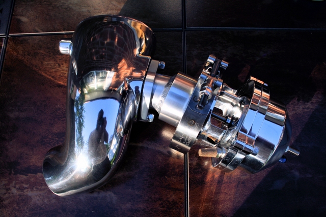
The valve now clears the alternator by about 3/8". Close, but no contact so I'm happy!
 ..
..
There are a couple parts now I'm still waiting for that should all be in this week (I hope).
A Boost gauge. A gauge pod for the A-piller. Some vacuum lines and a different air/cleaner assembly (since I have so much more space in front of the blower now) are all coming in this week. I discovered that the original belt tensioner on the BlowerWorks bracket was larger than what it was supposed to be (I have a 3.5" pulley and it was supposed to be a 2.75-3" instead) - so I'm waiting on that before I can install the blower belt.
I have to extend both the upper/lower radiator hoses to meet up with the re-located radiator (the stock hoses are now too short) install a few more minor parts (ignition coil, some sensors etc.) along with the parts I'm waiting on and I should be ready to start the car for the first time since I began the install.
I'm so anxious to drive this car again you have no idea...
Stay tuned for more updates. They should be coming a lot sooner now.
A few more miscellaneous pics:
The first one (I think) does the best job of showing just how much cleaner the engine bay is now that the massive stock shroud assembly has been removed and the rad pushed further forwards. Basically there's now nothing but a vast open space beyond the frame rail that cuts across the front of the engine. You can look straight down to the ground and see nothing but the floor underneath the car. Same goes for what's behind the radiator too. Nothing but wide open space. ANY work that has to be performed in or around the front of the engine will be an absolute piece of cake from here on out. Love it!
 ..
..
 ..
..
Yup. Back from the dead. I'm alive and well and so is the car. Well, not quite alive yet (the car that is) but it's getting close...
This little project has turned out into what has to be, the longest supercharger install EVER!!!.
While things have FINALLY started to move along recently - from the get-go, there's been delay after delay.
There have been some items that I literally waited month(s) for and I couldn't continue on without them. Not all were supercharger related components mind you, but there were a number of item's that I wanted to replace since I was already "in there" sort of speak - and figured now was the time to change them.
The biggest problem has been the waiting game. I've spent far more time just waiting for stuff, than actually working on the car itself, hence the reason for little or no progress since my last update.
In addition to waiting for parts, any issues with a part when it finally did arrived (say, it was the wrong part or didn't fit properly or whatever the case may be) that meant I had to send it back for a replacement. That meant shipping the item back to the vendor (1 week minimum delay right there) then wait for the vendor to prepare and ship a replacement part and ship it back out to me (another week again).
In a nut shell, the slightest mix-up with a part or order would add a 2 week delay at the bare minimum. If two parts needed replacement for whatever reason, there's another month of down-time.
The car as of today is about 90% complete, so I figured I'd update on what's arrived. What's changed and what I still have to replace, or am still waiting to arrive.
Steering components:
Nothing supercharger related, but something I was kind of forced to deal with. When I originally installed the new aluminium power-steering pulley that came with the BlowerWorks kit, the threads on the power steering pump got damaged during the pulley install and I wasn't able to press-fit the pulley on to the pump all the way.
Unfortunately, the damaged threads not only prevented my from fully installing the pulley, they also meant I was unable to remove the pulley either...
I was left with no choice but to buy a new PS pump - as well as a new pulley. Grrrrrr...
I have a knack of getting carried away when I work on my car and when all is said and done, end up doing more (and spending far more) than originally anticipated. This project was (unfortunately) no different.
The power steering line that goes to the pump was on so tight that I basically rounded off the edges of the nut trying to loosen it, so I just decided just to cut the line off with a Dremel and replace it with a braided line from DRM.
A new AC/Delco pump was ordered and of coarse, since I was also replacing the one line, it didn't make since to leave the others, so I decided to replace all the PS/PS cooler lines while I was at it. With the lines and cooler removed, I had a nice clear view of the factory 21 year old rack and pinion. It still worked just fine, but for how much longer?
Since I was already replacing the pump, pulley, lines and fluid, it didn't make much sense leaving the stock R&P in place. Especially since it was so much easier to get to with all the other components removed.
I went out and ordered a quick-ratio (code NS) z51 rack and pinion and replaced the rubber R&P bushing with poly's. Also ordered some shiny new ARP fasteners to hold it all in place.
Oh, and since everything else in the steering system was about to be replaced, what the heck, may as well install a new intermediate steering shaft while I'm at it.
 ..
..
Accessory bracket :
With the accessories all removed, I noticed that the accessory bracket itself was pretty cruddy looking. Not surprising given the fact it's not exactly a part you can reach in order to clean, so there was about 21 years of crap on it.
I decided to pull it out to clean it up and that's when I discovered that the threads that the tensioner and idler pulley bolts screw into were in pretty rough shape, so I began looking to find a replacement bracket. As it turns out, the accessory bracket for the later LT1 cars has been discontinued for quite some time now, so I set off to find a used bracket on FleaBay.
As luck would have it, there was some guy out in Missouri that just happened to have a brand new (NOS) accessory bracket in his possession still in the original sealed box, so I snatched it up. Wasn't cheap, but I prefer to buy new parts whenever I have the option to do so.
Some pics of the new brackt alone and with the accessories attached. I decided to replace all the old fasteners with Stainless ARP fasteners just for the hell of it.
 ..
..
A/C:
As I mentioned in a previous post, I decided I was going to (temporarily?) try running the car with no A/C and see how it would affect (or wouldn't affect) my day to day driving.
In all the years I've owned this car, I think I may have turned on the A/C twice. Once when I first bought the car (to see if it worked) and maybe 1 other time from that point on. Since the windows are always down and the roof always off whenever I drive this car, I decided to ditch the condensor, accumulator and all related A/C lines in favour of an AC delete bracket from TPIS.
If for whatever reason I decide I want the A/C back, it's just a matter of bolting up the compressor and lines back up which could be done in 20 minutes or less (I took them all out as a complete assembly).
The A/C delete bracket itself is machined from a solid block of billet aluminium, and is an anodized work of art. The amount of space it clears under the hood when replacing the compressor is amazing. A fairly significant amount of weight savings as well...
 ..
..
Radiator:
As many of you saw in my older posts in this thread. The factory radiator/shroud assembly had become a major issue with the install. The entire assembly was far too close to the engine and I didn't have enough clearance to fit the intake hat over the supercharger inlet.
Some suggested I cut up the shroud and modify the right-side fan assembly in order to clear the intake hat. I thought about it a bit and eventually came to the conclusion I'd be able to clear up a lot more space if I could somehow find a way to relocate the radiator further forwards. Doing so would not only add clearance, IMO, it would look better than cutting up half the shroud.
This was one of those parts that set the project back a few month's as I was communicating back and forth with one of our forum sponsors (Dewitts) in regards to making a custom radiator for my car.
Eventually, I came up with some measurements and a mounting idea that I sent off to Dewiits to have them make.
What you see here is the finished product. It took a looooooong time to get, but if this radiator cools as good as it looks, the wait and cost to have it made will have been worth it. Heck, even if it doesn't cool any better than stock, it was worth it just for the fact that I now have tonnes of space in front of the blower. I can run the supplied BlowerWorks intake hat, or just about anything else I want and have room to spare.
Your looking at a 2 core radiator built to the specifications I provided to Dewitts. It's dimensions are both lower and wider than stock. It has mounting tabs located on either side of the end tanks witch allow the radiator to be secured between the cars frame rails through (already existing) openings. It's running a pair of high performance Spal fans enclosed in a custom aluminium shroud.
The depth of the entire assembly is maybe 1/4 that of the factory rad/shroud and overall weight is actually less as well but due to the extra coolant capacity of the larger radiator, total weight might end up being very close between the two. Clearance has increased both in front AND behind the radiator. Pictures tell a thousand words and the following show how GM should have originally designed the rad/shroud assembly on these cars.
It clears up so much extra space, it's like working on a completely different car...
 ..
..
 ..
..
Blower inlet clearance: Stock Rad set-up compared to redesign. (Note: I'll no longer be using the "hat" style intake shown below, but a filter right off the blower inlet since I now have the clearance to do so.)
 ..
..
Bypass valve:
Originally the BlowerWorks system came with the standard Vortech valve. Although I'm sure it would have worked fine. It didn't "LOOK" the part.
I wanted something that would not only look better, I wanted something that would SOUND the part as well and just as importantly, would not be a restriction later on as engine mods progressed. Enter Vortech's Maxflow BV57. This thing is just MASSIVE!! Never seen another valve this big before on a street car. It's ridiculous. Yes, it's overkill right now, but I have big future plans for the little LT1.
Below is the new BV57 compared to the previous Maxflow Vortech valve:
 ..
..
With the BV57 venting out into the atmosphere, this car's going to sound like a street sweeper. Can't wait.
Of coarse, going this route created some new problems. For one, because this valve is not application specific, it requires a flange to be custom made for each individual application. So Greg at BlowerWorks was kind enough to machine a gorgeous looking adapter which would allow me to run the valve on my Vortech air intake. The adapter allowed the valve to mount perfectly.
Unfortunately, I wasn't out of the woods just yet. Due to the massive size of this valve and the position is was located in with the new adapter, it was right smack dab in the way of the alternator. Great. Another set-back.
The picture below shows the original straight adapter Greg made for me. Awesome piece, but unfortunately, put the valve in contact with the alternator. In order to solve the problem I had the adapter cut shorter and re-welded at a 45' angle to position the valve away from the alternator. You can see below in the pictures the re-worked "angle" adapter.
 ..
..
... and a few pictures of the modified adapter/valve assembly
 ..
..
The valve now clears the alternator by about 3/8". Close, but no contact so I'm happy!
 ..
..
There are a couple parts now I'm still waiting for that should all be in this week (I hope).
A Boost gauge. A gauge pod for the A-piller. Some vacuum lines and a different air/cleaner assembly (since I have so much more space in front of the blower now) are all coming in this week. I discovered that the original belt tensioner on the BlowerWorks bracket was larger than what it was supposed to be (I have a 3.5" pulley and it was supposed to be a 2.75-3" instead) - so I'm waiting on that before I can install the blower belt.
I have to extend both the upper/lower radiator hoses to meet up with the re-located radiator (the stock hoses are now too short) install a few more minor parts (ignition coil, some sensors etc.) along with the parts I'm waiting on and I should be ready to start the car for the first time since I began the install.
I'm so anxious to drive this car again you have no idea...
Stay tuned for more updates. They should be coming a lot sooner now.
A few more miscellaneous pics:
The first one (I think) does the best job of showing just how much cleaner the engine bay is now that the massive stock shroud assembly has been removed and the rad pushed further forwards. Basically there's now nothing but a vast open space beyond the frame rail that cuts across the front of the engine. You can look straight down to the ground and see nothing but the floor underneath the car. Same goes for what's behind the radiator too. Nothing but wide open space. ANY work that has to be performed in or around the front of the engine will be an absolute piece of cake from here on out. Love it!
 ..
..
 ..
..
Last edited by LT1*C4; 06-23-2013 at 10:05 PM.
06-24-2013, 09:44 AM
#40
Racer

I'm glad to see you've found a solution to making more room in the front, but I wonder what effect aerodynamically it'll have in the front of the car.
I wish I had all that room. I'd slap a filter right on the intake. I'm running an intercooler and have barely any room to spare. I'm currently trying to figure out how to run my intake piping where it wont collapse and fit around a 32MM front sway bar.
When you get it running again let us know how it all works out. Looks great!, and thanks for taking the time to document.