When you click on links to various merchants on this site and make a purchase, this can result in this site earning a commission. Affiliate programs and affiliations include, but are not limited to, the eBay Partner Network.
Holley Sniper Notes and Tuning Supplement for users by users...
Current Revision of Post #1 listed at the end of post. Content is constantly being updated and edited.
I have a 1978 Corvette with a stroked 385 centrifugal supercharged gen 1 small block chevy (see C3 � Centrifugal Supercharger (ProCharger) thread for more details.) I�ve owned the corvette since 1994 and have tinkered with many mods and systems over the years. The car remained carbureted until 2019 with an HEI ignition system with several revisions throughout the years. Originally, when I considered EFI, throttle body / port injection was too costly in my opinion to make the switch from one fuel delivery system to the next. In the last 5-7 years, many of those systems have come down in cost, especially the throttle body EFI systems. The Holley Sniper system is relatively powerful and relatively inexpensive for what you get. So, I decided to make the switch � largely due to a better control of fuel / timing for a blow through super charger application.
As I started using the Sniper system, I like most people, slapped that thing on, ran the startup wizard, and drove the car. Generally speaking, that worked pretty well. At that time, I didn�t know what I didn�t know. The car ran pretty good considering I hadn�t done anything to it in terms of adjusting the Sniper software. However, once I started reading and searching other sources for information, only then did I realize that the software was pretty powerful, and my engine would run better � if I knew how to adjust it better.
Over the last years - since 2019 - I have learned to tune the Sniper, troubleshoot, upgrade, etc... making the product truly remarkable. The Sniper may not be the best out there in terms of aftermarket EFI, but much of that stems upon how much you know how to manipulate it and modify it to fit your needs. I have reached the point, after years of tweaking and fixing, where I can bring my experiences to others regarding this platform.
Disclaimer: I�m a Sniper user, not a Holley Technician. I didn�t invent nor design any of the following information. It was a gradual process of learning from my own experiences, other users, Holley technical forums, EFI systems pro, technical bulletins and other sources. My intention for this thread is to bring together information that I spent time researching � into one place, and answer some of the common questions that surround the Holley Sniper platform. The goal here is to not necessarily re-hash the instruction manual, but to provide a helpful guide or �notes� while working through a Sniper install and tuning process. This thread is a work in progress � a living document.
2. INITIAL SETUP CONDITIONS:
Running the wizard to setup your Sniper at first � is the best way to start. It will load all the base curves and other parameters that will get your engine running. It�s important to note that these curves and initial parameters are a good STARTING POINT, but not necessarily where you will end up with your engine tune. I have found that the simple timing tables are too abrupt (not smooth transitions), the base fuel curves to be too rich, AFR tables too generic and abrupt, cranking parameters too rich, scaling not fit for application, etc� I�m not implying that the wizard is bad for your car / application, but it�s definitely not going to be optimized. Holley has to make a bunch of operating parameters and assumptions on a very wide range of engine combinations. There is no reasonable way to assume they are going to �nail� your particular engine needs with an �out of the box� EFI tune.
Additionally, if you are not using a laptop or similar computer to use your Holley Sniper software, you are severely limiting your ability to actively make your system better.
2a. Physical Installation
One of the greatest myths of the EFI conversion is the physical conversion itself. It's not really bolt on and go. If you have a carbureted setup in gen 1 SBC, you have to deal with a mechanical fuel pump delete, possible fuel line modifications, fuel tank changes / modifications, adding an electrical fuel pump (in-tank or external), adding fuel filters, adding electrical systems to support, wiring modifications, ignition system changes etc... Granted, there are a lot of new products out there that make some or all of that conversion easier, but very rarely a "bolt on and go" easy. There are also some upgradeable changes you can make to the Sniper system to make it work even better. There is a section later that references upgrades for a more detailed discussion.
2b. Scaling RPM vs Engine Load:
Typically, the Holley Sniper wizard sets up the X and Y axis for the base fuel curve with engine pressures and RPM that is scaled in such a manner that some of the graph is not usable. For example, the RPM may go to 8000 on the X axis. Does your engine rev to 8000 RPM? Does your engine have forced induction � if so, how much? So does the engine load axis (Y) have boost but you don't need it? Do you prefer Kpa units or psi for engine pressure? All these things can be manipulated, and I would recommend doing that AT THE BEGINNING of your setup since the software will not re-scale your data if you change the scaling later. Also, you don�t have to have it linear. You may want the boost pressure to go in 2 psi increments, but at 0 psi transitioning to vacuum, you want 1 psi increments (or less). That would increase the fidelity of where your engine runs more often giving you more data points where it is needed the most. Once you get the base fuel curve axis set, it will transpose to your other axis. You will need to tell the AFR table to utilize your fuel table as its source for its axis.
All of the Holley Sniper software graphs can be manipulated similar to an excel spreadsheet. The data can be erased pasted into an excel workbook, and reinstalled in the same way. Copy and paste functions work just like you�d expect.
Remember, the table's data will NOT change when you make changes to the axis. This is problematic to the software (and an area where Holley should improve it), but not the end of the world. I have found and modified excel worksheets that will scale data with the change in axis. Then you copy and paste the new data to the Sniper table and you are good to go.
2b. Scaling Coolant Temperature:
The default coolant temperature range for the Holley Sniper is -40F to 260F. That temperature range may make sense for some Sniper applications, but not for most C3 owners. Even C3 owners who live in the frozen tundra, don't typically take their C3s out into the frozen tundra conditions. Re-scaling the temperature axis (the X-axis) is possible, but not as straight forward as the fuel tables. In order to re-scale your coolant temperature scale select the "sensors" ICF. Then select the "CTS" tab. At the very top, is a CTS scale set of cells.
Pick your low scale number (example 25F) and select the high scale number (example 250F). Now highlight ALL of the numbers in the scale cells and right click => "Fill Row Values". The software will fill all the values in between your high and low scale with a linear scale of numbers. In this example, the values are in 15F increments. This will now re-scale all of your tables that are based upon coolant temperatures EXCEPT "Timing vs Coolant Temp". Change that one manually like you did the sensors. I'm not sure why the timing coolant temperature scales don't move too. Software glitch? **Important Note** Once again, the data DOES NOT re-scale. You must re-scale the data manually or with a spreadsheet or similar.
2c. AFR Table:
The wizard generates a simple set of AFR parameters. The graph is not smooth, therefore during engine load and RPM changes, the AFR transition will be abrupt. Obviously, that is not a good way to run an engine. There are strategies that can be used to generate a smooth transition graph and keep good AFR parameters for different operating loads. The reason I bring up this table; if you don�t get the AFR tables correct everything the Sniper does is to fulfill your desired AFR targets. It doesn�t learn this table, nor modify it in any way.
2d. Single Plane vs Dual Plane Intake Manifolds:
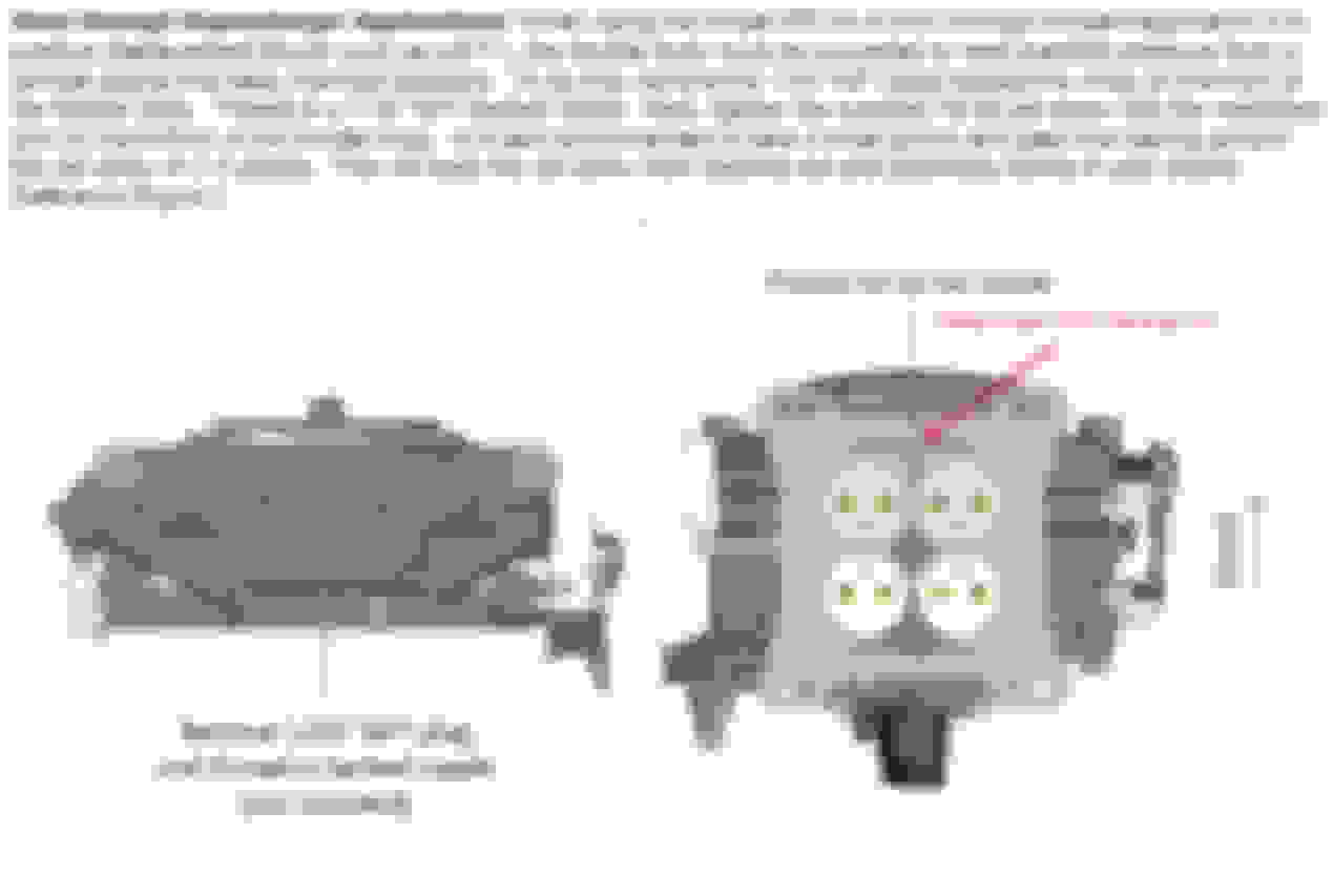
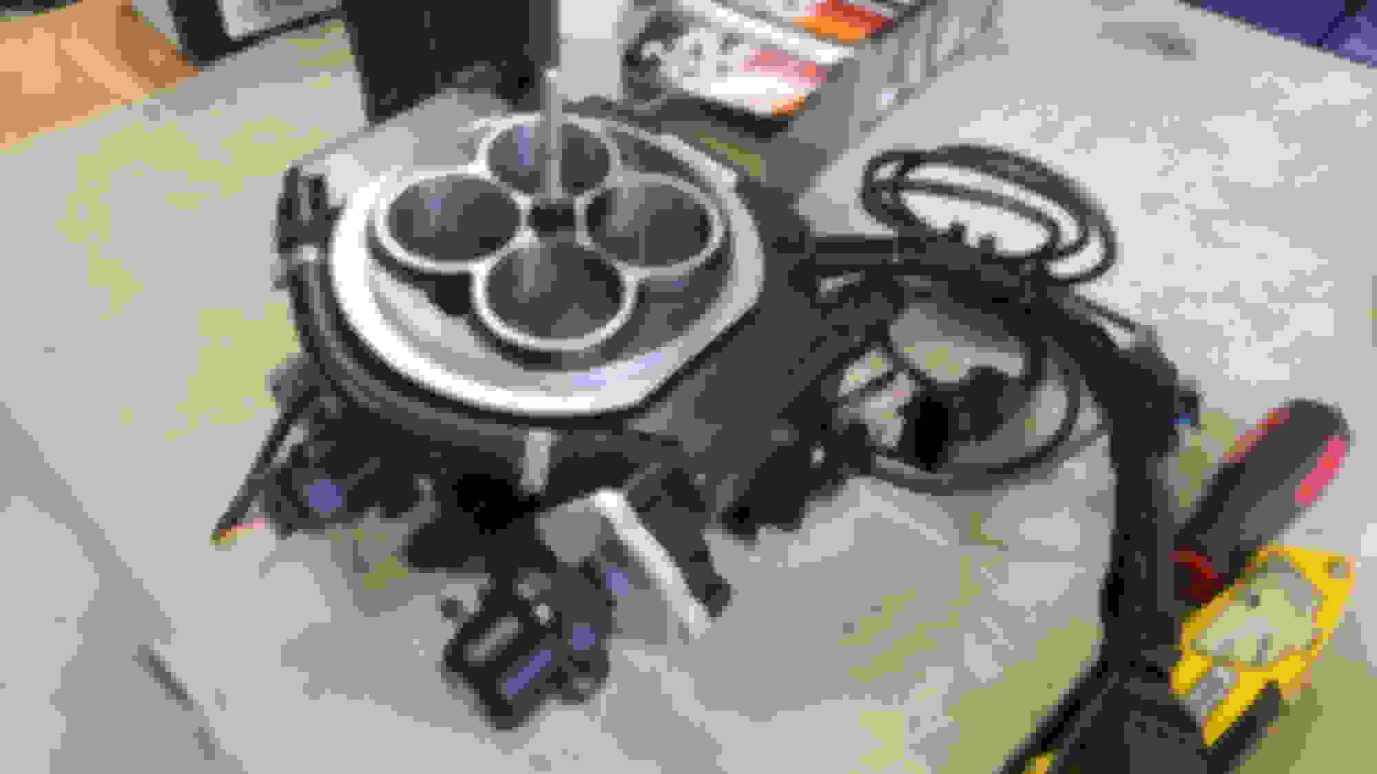
There are many discussions on how well or not well certain manifolds work with throttle body EFI manifolds. Both manifolds will work, and I have personal experience using both. A couple items of note: single plane manifolds don�t suffer from the same loss of torque / throttle response that a carburetor does at lower RPM. Therefore, it is usually desirable to go straight to a single plane manifold with EFI because you gain the advantages but none of the losses that way. There are also some ideas out there that a divider on the dual plane will cause engine load detection imbalances. The problem I have with this theory is that the internal MAP sensor is in the center of the Holley Sniper with four symmetrical ports going to EACH side of the dual plane divider. It is hard to conceive that it would be possible to NOT feel manifold pressure on both sides of the divider at all times.
Notice that the internal MAP sensor is at the centerline of the Sniper base plate. There are 4 symmetrical ports or channels that extend onto both sides of the manifold. That would be the equivalent of running a small spacer or similar concept. Therefore, keep this in mind before worrying about machining down a dual plane manifold divider. If your Sniper is configured like above, there should be no need for that.
2e. Exhaust Systems:
The Sniper system doesn�t really care about the exhaust system, but it does care about a good O2 reading. Due to a lot of O2 sensor issues I have a whole section devoted to O2 sensor discussions. However, placing an O2 sensor in the correct orientation is important to ensuring the Sniper gets good readings. Side pipe configurations are the most challenging to make this work. I have side pipes, and I have had good results with a less than ideal placement for my O2 sensor.
2f. EMI:
EMI, or electromagnetic interference can definitely play a role in messing up the Sniper. There have been plenty of issues documented on forums and tech sites to warrant special attention to this. Because the Sniper ECU is internal to the Sniper, it can be more susceptible to EMI. The manual mentions the issue and how to mitigate EMI. I�m not going to re-hash that, but I can state that REASONABLE measures should be taken to minimize EMI. If you are wrapping every wire with grounded aluminum while you drive with an aluminum hat, you have another issue beyond EMI. Keep your spark plug wires and coil wire away from your system wiring. If they have to cross close, cross them at 90 degrees if you can. Also keep your O2 sensor wiring away from the spark plug wiring if possible.
The manual states numerous times that you must use a clean power source to the Sniper, directly from the battery. Every attempt should be made to do this, and that clean source of power is vital. It affects many aspects of the Sniper�s ability to function properly. In the C3 corvette, this becomes challenging due to the positioning of the battery. I ran a direct source wire from the battery to the Sniper (as well as ground) to accomplish this. This is hard to do if you don�t have some of your Corvette taken apart. I routed my wires through the console area to the firewall to the Sniper.
2g. PCV:
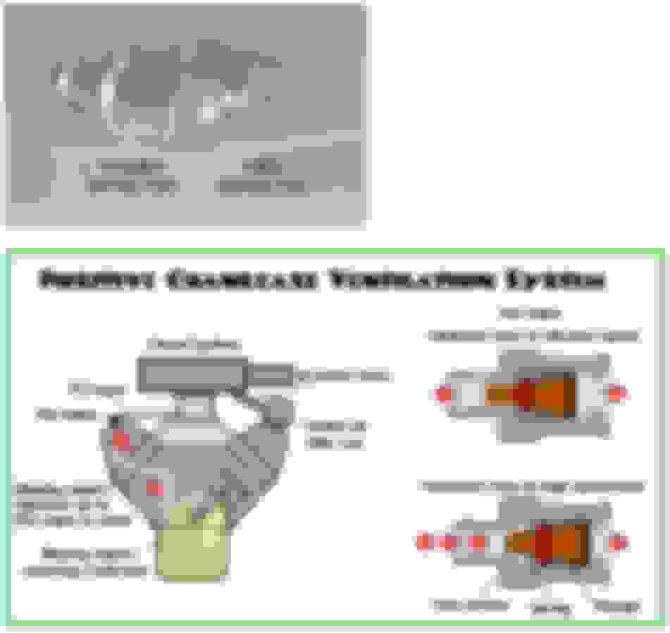
PCV generally should be used in any street driven car. It will reduce crank case pressure, reduce the chance of leaks, reduce oil contamination, so on and so forth. However, due to the nature of closed loop compensation adjusting fuel based upon O2 exhaust levels, it is imperative that PCV system doesn't fluctuate oxygen into the intake manifold. Variable PCV systems can sometimes do this creating lean conditions or spikes � causing tuning issues. Most of the information that I read or experienced recommended going to a fixed orifice type of PCV valve. Although not always necessary, it may simplify tuning issues. As far as PCV valves go there are different products out there, or you can make your own.
There have been some rare cases of erratic idle and tuning issues with the PCV systems. Large camshafts can also cause PCV valve malfunctions, due to unstable idle vacuum. In some applications, using the "fixed orifice" type of PCV valve, can be better than the conventional "variable orifice" PCV valve; especially for EFI applications. I like knowing the predetermined vacuum draw (PCV orifice) is always the same. I think the idle is more consistent too. FYI: For naturally aspirated engines only - unless you install a check valve or the PCV has a check valve rated for boost pressure installed.
"Fixed Orifice" PCV Valve Part Numbers:
GM OEM 12572717
ACDelco CV4000C
NOVO 2377
FRAM FV410
BWD PCV484
Wells PCV371
Airtex 6P1241
CarQuest 76-2698
MicroGard PCV2377
NAPA/Echlin 2-9485
AutoZone/Duralast PCV1009DL
Standard Motor Products V372
FYI: If you need the 90� version, simply reuse your old plastic 90� plastic barb fitting. The 90� black plastic hose barb pops off the old PCV & onto the new PCV valve.
Dual Flow Adjustable PCV Valve - M/E Wagner Performance: LINK
This aftermarket PCV valve can also operate in "fixed orifice mode" (for low idle vacuum camshafts), and still retains backfire & reverse flow protection (check valve) for use on naturally aspirated & forced induction engines. It will also work a in a dual flow mode and is adjustable / tunable / repairable. It is an awesome PCV valve, but don't expect it to be $1.99 at your local car parts store.
M/E Wagner Dual Flow PCV:
2h. Timing:
Utilizing an EFI system without also adding timing control really removes added benefits of the EFI system. I and others would not recommend moving to EFI if you don�t intend on also moving the timing aspect to the ECU of the Sniper system. My choice was to integrate the Hyperspark system, but there are other systems to consider that perform as well. Some of the added benefits of Sniper controlled timing are graph based timing, idle timing adjustment (to smooth idle RPM), cranking timing, timing retard under boost to name few. All of these parameters can be changed by adjusting a graph and saving the new parameters to the ECU. Bam, your timing is now different and you didn�t have to touch your distributor cap.
2i. Injector Selection and Sizing:
Although the Sniper has just a few options in terms of injectors, you can manipulate the injectors used, as well as the pressures for your system. Generally speaking, the design system pressure for the Sniper is 60 psi +/- about 5 psi. However, some have run the Sniper at 43 psi with different injectors with no noticeable change in drivability. I mention all of this to state that with a little bit of knowledge, you can experiment with different parameters for your Sniper if you want to. There are some limitations to adding fueling capability to the Sniper. You can't just add infinite injector sizes and expect the HP rating to be forever capable. Obviously having enough fuel delivery is one limitation, and the other is air flow through the system. The Sniper / Super Sniper throttle body can generally handle enough air flow for about 750 HP. If your application may exceed that number, it would be best to move up into the X flow or beyond type of systems.
In order to manipulate the Sniper for different injectors there are some basic information you have to deal with. The Holley Sniper uses a 'LS3' style injector. That injector is one of the smallest injectors on the market, and has lots of applications since the early 2000s. They will still be capable of flowing way more fuel than you'll need - depending on the injector - but they come in a relatively compact package.
Holley Sniper Injector Characteristics:
Injector Plug: USCAR / EV6
Injector Body: Pico or Small
Driver Type: 12 vdc saturated circuit
O-Rings: Validate O.D. on both ends. Some LS3 injectors came with a smaller size on the bottom of the injector.
High impedance injectors (usually around 12 ohms but can range from 9-15 ohms).
The Sniper defaults to running a 58-60 psi fuel system. If you utilize an external fuel regulator you can vary the fuel pressure to meet the needs of other system fuel pressures. Two of the most common EFI fuel pressures are 43 psi (3 bar) and 58 psi (4 bar). Out of the box, the Sniper will run 60 psi (basically the 58 psi system) or 4 bar. However, it is capable of running on a 3 bar system. The probable reasons for the rigid use of pressure / injectors from Holley (I am guessing based upon talking to Holley and others in the EFI world):
Liability. Holley's official stance on changing the injectors on the Sniper units: only they can perform this action.
Holley's stock injectors are rated at 100 lb/hr @ 60 psi. They have entered all the data for the injector and ECU for the end user.
Perhaps they don't want users putting other injectors into their EFI units?
Lack of test data for other injectors used in the TBI?
Using different injectors can be done. Holley offers a 120 lb/hr injector for the Terminator system that will work in the Sniper. That will up the total flowrate at 60 psi to 480 lbs/hr. This can be useful for power adders who need additional fuel margins during WOT operations. You can use even larger injectors (Bosch for example) that will flow even more. The thing you have to balance as a 4 injector Sniper unit is max fuel flow vs idle quality. If you run a large injector (X4 @ 60 psi) you may have plenty of fuel capability at WOT, but bad idle quality at 0% throttle because the injector flows too much fuel at its minimum injector opening time.
Another option is to run the system pressure at 43 psi (3 bar) with a larger injector. The lesser fuel pressure will flow less fuel at lower duty cycles - allowing more stable idle fuel delivery while still maintaining a large higher end total fuel flow. In the example below, an injector was used that can supply around 150 lb/hr @ 43 psi. Typically, the 'Fuel Injector Information' is where you will input the injector specific data usually available from the supplier of the injector. That information has to be as correct as you can be - for the ECU and injector to properly calculate fuel requirements. In the below table, the 'Rated Flow per Injector', 'Rated Injector Pressure', 'Minimum Injector Opening Time', and 'Injector Off Time' table must be known for the specific injectors used. Then you must have a way (via external fuel pressure regulator) to adjust your actual system fuel pressure to the rated injector pressure and enter that value in 'Actual System Pressure' field. Once these things have been done, the Sniper is going to have to learn the new fuel needs for the engine.
In every other regard, the 43 psi fuel pressure system worked just like the 60 psi system. Once the base fuel tables were learned and well tuned, everything else tuned up nicely. In summary, the Holley Sniper will respond favorably to numerous types of injectors and different EFI pressures.
In order to understand injector size requirements, we can use some simple math that is commonly used to estimate injector size requirements. Using the 100 lb/hr standard Holley Sniper injector, we can use the thumb-rule for BSFC or Brake Specific Fuel Consumption. This number represents the amount of fuel an engine will require to produce one horsepower in one hour expressed in pounds of fuel per horsepower per hour (lbs/hp/hr which is commonly abbreviated to lbs/hr). The conventional BSFC number for a gasoline engine has been 0.50 which means the engine would burn a half a pound of gasoline per hour to make one horsepower. Higher efficiency engines will lower than number to say .45 and super charging an engine typically will raise that number to .65. So, the 100 lb/hr injector Sniper estimation would look like this: (100 lb/hr x 4 injectors) / .5 BSFC = 800 HP. This is a THEORETICAL number, not the final number we would consider for fueling purposes. But theoretically speaking, 400 lbs/hr should drive 800 HP.
Unfortunately, the realities of internal combustion engines are not quite that simple. First of all, this allows absolutely no room for variation or if we overachieve with our engine and actually make more power. This simplified calculation does not allow room for additional fuel flow or other potential errors.
Injectors deliver fuel in a linear fashion through a majority of their operating range. However in the lower and upper 5 to10 percent of their flow ranges, the output becomes non-linear. Although most EFI systems have tables to correct this non-linearity, it is best to avoid operating the injector in these ranges.
For this and other reasons it is common practice to reduce the injector�s duty cycle. This is expressed as a percentage of operation. An injector that is held open continuously would be rated at 100 percent duty cycle. At a 50 percent duty cycle, the injector is flowing fuel only half the time. To allow for inherent injector variables, industry standards recommend sizing injectors for about a 70% to a maximum of 85% duty cycle.
Taking this into account, this effectively reduces the amount of fuel the injector can supply by 30 percent from its 100 percent duty cycle. This means if we were sizing an injector for 800 horsepower, we�d add 30 percent to the 100 lbs/hr (100 x 1.3 = 130). In our example above, we could reduce the effective HP by 30% to get an idea on how much the Sniper may be rated for (560 HP with a 70% duty cycle). Now the Super Sniper is rated for 650 HP, which would be a duty cycle of somewhere between 80%-85% based upon these calculations. That is not unreasonable since Holley is giving its customers a HP limitation with the as rated injectors.
These calculations / numbers change when dealing with power adders such as forced induction. You may have seen horsepower estimates for EFI systems or injectors where the peak horsepower potential changes between normally aspirated and supercharged or turbocharged applications. The fuel flow numbers will change mainly due to the BSFC number applied to that particular supercharger or turbocharger. Conventional wisdom states that it is wise to choose a larger injector for boosted applications in order to have sufficient fuel flow beyond that required for the engine�s expected power level. This is important because the consequences of running a too lean air-fuel ratio on a boosted engine are nearly always disastrous. However, there are multiple reasons for choosing a larger injector.
Boosted engines, especially belt-driven supercharged engines consume a significant amount of crankshaft power merely to drive the supercharger and the larger the supercharger, the more horsepower it takes to spin the blower under boost. It is not unusual for a large centrifugal supercharger to consume more than 100 shaft horsepower to move the air to create boosted power. Even small centrifugal superchargers generally demand upwards of 50 to 60 horsepower to spin.
So, using the same basic calculation, substitute the BSFC number of .65 for forced induction applications. I'll use my current engine's parameters for my example injector calculation. My Sniper has the 120 lbs/hr injectors. So working the equation from there: (120 lb/hr x 4 injectors) / .65 BSFC = 738 HP x .85 Duty Cycle = 628 HP (forced induction). This is probably a conservative number even with the 85% duty cycle, but again, it allows us to have a good idea on the injector size needed for our applications.
3. DATA LOGGING:
Data logging is the single biggest reason EFI trumps more traditional fuel delivery systems. If you have any aftermarket EFI system, and you are not using a computer / laptop to analyze your engine data, you might as well go back to a carburetor. It�s like putting in your distributor, but not checking the timing after installation. You get my point. You are severely handicapping yourself and your systems ability to maximize its effectiveness.
I personally data log every drive. You can set up triggers for data log taking. In this example, I would set the start of the data log based upon a condition of engine RPM. Once the engine RPM goes above say 35 RPM => start data log. So, upon engine crank, the data log function begins to capture data. It will continue until you stop it manually or turn the ignition off. I�ve also set up data logs based upon a sudden drop in system voltage (to get cranking data), but the conditions are numerous. You could set up many potential conditions for data log taking.
Once you have data to look at, you can now start the process of improving engine running characteristics. For example, if your data log is an engine start from say 40 F coolant temperature, and you notice that the closed loop compensation is + 22%, you know that the current coolant temperature enrichment curve is not adding enough additional fuel at that temperature. So, you can adjust that curve (to be described later) to more accurately provide the correct amount of fuel at that given parameter.
Another important feature to use in a data log, is the overlay feature. It is found under the "Data log" drop down menu => "Activate Overlay". The nice thing about that feature is that you can see on the Sniper tables a graphed line showing you where the current zoomed section of your data log interacts with your engine tuning graphs.
In the above representation, it looks to be an acceleration event, followed by deceleration or shift. There is a quick rise in engine load, with RPM coming up, then a drop in engine load. We don't know the time frame at this time, but you can also see where the cursor is on the data log, because it shows up as a dot or circle on the table above. These features are very important when you are trying to make manual tuning adjustments in very defined operating areas of your vehicle.
4. TUNING TIPS � TARGET AFR TABLE:
Before you can really expect your Sniper platform to learn anything, you must understand that it is learning to an AFR setpoint. That AFR setpoint comes from one place, the 'Target A/F Ratio' table in the fuel ICF. Generally speaking, that table is generated by the Sniper's wizard for most applications. The table is generated by the end user answering a few questions: What AFR reading do you want for Idle, Cruise, and WOT. An example of the 'simple' table in 2D mode is shown below:
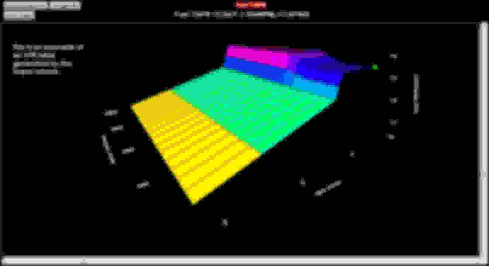
There are couple of things to note here. First off, the graph will take on the scale that the user (or wizard) has defined on the base fuel graph. So if you haven't edited your fuel scale, it will be the default wizard scale. In this scale the units are PSI. I generally do all of my graphs in PSI, not KPA. That is simply a preference thing, but I don't think in KPA. Notice the RPM and manifold pressure axis. This wouldn't be a good graph for most applications. You would lose fidelity in both the X and Y axis due to unused areas of the graph. Looking at the table, it doesn't look horrible in terms of a graph, but check it out in 3D:
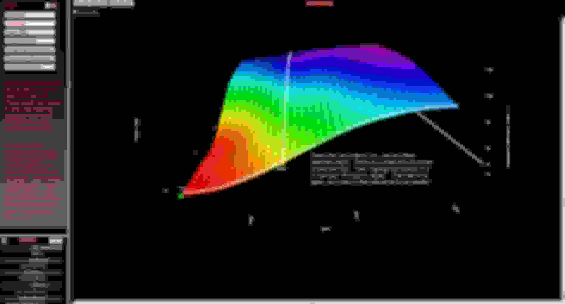
You can really see the transitions in the 3D a lot better. They are relatively abrupt, not smooth. It isn't super important to have an ultra smooth AFR table, but if you end up with an abrupt change in an area that your car stays in, it will end up with large swings in target AFR.
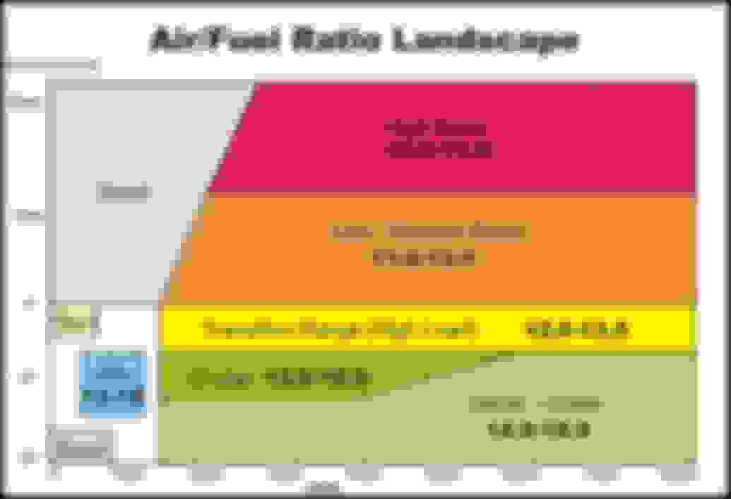
In this particular table I wanted to emphasize the transitions across the table. Most engines can run leaner during no load or deceleration events. The idle area can be finicky sometimes - especially with larger camshafts. I like to set my builds slightly richer in the idle area, but not too much. Also pay attention to where your vehicle will idle. You want that area to be flat - so your EFI unit is not chasing around a moving target. WOT areas need to be richer than cruise areas. Generally speaking you usually see around 12.5:1 through 13.0:1 numbers. If you run a power adder, you'll want even more fuel, reducing the AFR to the low 12s or even 11s for higher boost applications.
We also have to get into the areas of the table. What area does your engine idle in? Where are the cruise areas? What about acceleration areas and of course, wide open throttle / WOT with boost? Below is an example of another AFR table that is better blended. It has overlaid areas that describe typical engine behavior as well. Do not pay too much attention to the actual AFR numbers, every engine is different, but conceptionally, the numbers are usable. Most of the 'out of the box' tables that are generated by the wizard I feel are too rich. Holley probably does that to protect themselves against liabilities since running a little rich reduces engine damage risk. What I have found is that the AFR table AND the base fuel table are both generally biased rich, there is a lot of fuel pulled out at first - especially in the idle areas. However, remember, the Sniper doesn't learn an AFR table. It is what it made it or you make it. So it will never correct itself from an overly rich target AFR table - you must do that!
There are areas of the table above that the Sniper unit really doesn't "follow the AFR table" because it won't be in closed loop. For example, while accelerating moderately to heavily, CLC will = 0. Throttle off deceleration will also have CLC = 0. Your acceleration enrichment or AE + your base table are in control. In these cases, since the ECU has turned off the CLC, you won't get fueling corrections. As will be discussed - those fuel scenarios need tuning. Also, during a deceleration event, your fuel will go to wherever the base fuel table dictates for fuel flow in that area, and the AFR will fall where it falls. In the above table, the desired AFR maybe 14.9:1, but since the ECU isn't compensating your AFR might be 13.1:1. You may have to manually take some fuel out in the lower parts of the base fuel table to lean out your mixture in those areas. That will be especially true for manual transmission cars - due to the driving style gear management / clutch operation.
Typically you see the stoichiometric AFR value of 14.7:1 thrown around. That is theoretically true, but due to todays fuels / blends the reality would be closer to 14.2:1 or so. A lot of these numbers are very subjective to the engine / tuner. However, if you are in the ballpark, your engine will run. Are you going to be able to tell - especially getting on the throttle - that your engine likes an AFR of 12.7:1 vs 13.0:1? Probably not. You could probably set your whole table at 14.0:1 and the engine would run fine in many circumstances. The end user will have to do some research to find AFR tables that work best, or have a tuner or tune session set them.
Another thing to note, there is a drastic difference in setting an AFR fuel table to pump gas (probably has some ethanol) vs an E-85 tuned car. I don't have any experience with E-85, but you have to either lower your AFR numbers by about 32% or have a E-85 in your drop down - which also affects the AFR numbers you should use.
Here is the above table, in a 3D graph. If you compare that to the wizard graph from above, there is a big difference in transient AFR values.
The table below is a guideline for setting up an AFR table. Again, every engine is different, but this table should get most users heading in the right direction.
5. TUNING TIPS - BASE FUEL TABLE:
**Important note** The base fuel table has to be closely tuned (learning complete) before any of the other tables should be modified. The reason for this: most of the other tables build off the base table as a reference or modifier.
The base fuel table is exactly that, the base fuel table for your engines fuel delivery needs. It is the only table that the Sniper learns to. It is the table that all of the other tables reference off from. If the base fuel table is not tuned well, you shouldn't be tuning any of the other tables yet. If you do, you end up chasing your tune around. Ask me how I know this... As discussed before, run the wizard to get a rough base tune based on your engine input parameters. Then re-scale the base fuel X and Y axis to best reflect your engine running parameters. I typically run 500-6500 RPM and -11 to 0 psig then 0 to +8 psig (for boost) on my C3 setup. That best fits my engine parameters, but anyone may have different builds and engine specs. Remember, the re-scaling doesn't change the wizard generated base fuel cells. I have some excel spreadsheets that re-scale the data, but I wouldn't worry about that yet. The closed loop compensation and "learning" will start to modify your fuel delivery to run the engine. It's important to re-scale the axis to get the best fidelity for tuning.
The spreadsheet that I keep referring to I got off from the Holley Sniper Tech Forum. I modified it to fit my needs, but I didn't create it from scratch. What it does is allows the user to enter the initial scale, and initial values of say, the base fuel table that the wizard generates. Then, once you've rescaled the axis, you enter the new axis, and the spreadsheet does that math and fills in the new axis sheet with the correct values for the new scale. Then you simply copy and paste the new table vales BACK INTO your base fuel curve table. Now you effectively have the old wizard values in the new scale you created.
Also keep in mind - the other charts that have RPM vs Engine Load didn't re-scale either. For example - timing and learning to name a couple. Those graphs should be re-scaled as well. That is why it's important to do the re-scaling early on, before you've started to really dial things in. It makes it a little easier and less critical in the beginning.
Once you get starting values for the base fuel table, the only way to get it tweaked in - is to drive the car. Since the closed loop and learning need to be able to do their thing, the car needs to run. Before you can really start messing with the other aspects of tuning, the base table needs to be "done learning". Generally, learning is done when you start seeing learning values consistently around 5% or less. That is assuming that your driving conditions are generally similar from a day to day basis. Sometimes you might see 7%-8% in certain conditions, but once your are in the single digits for learning %, that area of your fuel curve is pretty close. These last statements are also assuming that you are "transferring learning to base" of the learn tables to the base table. I have a whole section on the "learning", and will try and add more detail there. BUT if you never transfer learning to base, you aren't modifying your base table. That isn't anything horrible, but you want your base table to be as close to what your engine wants / needs. It can't do that if you never modify it.
Here's the wizard axis and fuel table:
Here's the modified axis and more seasoned fuel table:
Notice the difference in the base fuel table that the wizard provided vs the table that was eventually learned. For example, in the cell at -7.0 psig vs 1500 RPM, the original wizard has 68.5% volumetric efficiency vs 39.8% volumetric efficiency. The wizard had my engine at almost twice the amount of fuel required at that load! If I hadn't gradually modified my base curve based upon the learning, the learning modifiers would be around -40% fuel in those areas. That is why I stress to new Sniper owners - your must take a part in the tuning! The Sniper can only do so much without user input. The goal is to make your tuning so good, CLC doesn't have a job - or you could run your tune in open loop and the engine would run fantastic!
Most of the base fuel table can be populated by learning as you drive the vehicle. As you "transfer learning to base" smooth out the fuel areas so you don't have abrupt changes in fueling. Eventually, the amount of learning should get smaller as you keep updating the base fuel table. If you don't update the base fuel table, the learning section will still add or subtract learned fuel, but it won't alter the base fuel table. So if you don't update or transfer the learning to base, your learned table will stay the same once fully learned. The reason I like to update my base fuel table is so the base fuel table actually fully represents the accurate fuel needs for the engine. After that, your learning numbers should start to shrink to < 10% or even smaller.
There are cases when manual tuning in an area needs to be performed. Sometimes radical cams with low vacuum and large overlaps cause false lean conditions. In those cases the idle area may need manual tuning as well, and you may have to phase out learning and CLC to keep the ECU from altering your manual tune. I've also noticed that deceleration areas of the tables are often not tuned well - especially for manual transmissions. The reason for this is due to how the Sniper learns. During a deceleration (TPS = 0%) AND the RPM is still > transition to idle RPM, there is no learning taking place nor does CLC kick in. So you are left with your actual fueling in the lower areas of the base table. Often times these areas from the wizard - are too rich. You'll notice that during a engaged manual transmission slow down, AFR will go to 9-12 (it varies), and you are in the bottom few rows of the base table. Automatic transmissions don't see this as much because you can run a much higher transition to idle setting - which will also get you some CLC to help with tuning. So I ended up highlighting the bottom row and offsetting the fuel by some relatively small percentage, then blending it with the "fill column values" from a couple or few rows above. So it ends up looking like a bend or curve down at the bottom of the base fuel table. After the initial adjustments I would take the car out, do some deceleration events with a data log. Then I would adjust the fuel again based upon my AFR in those areas.
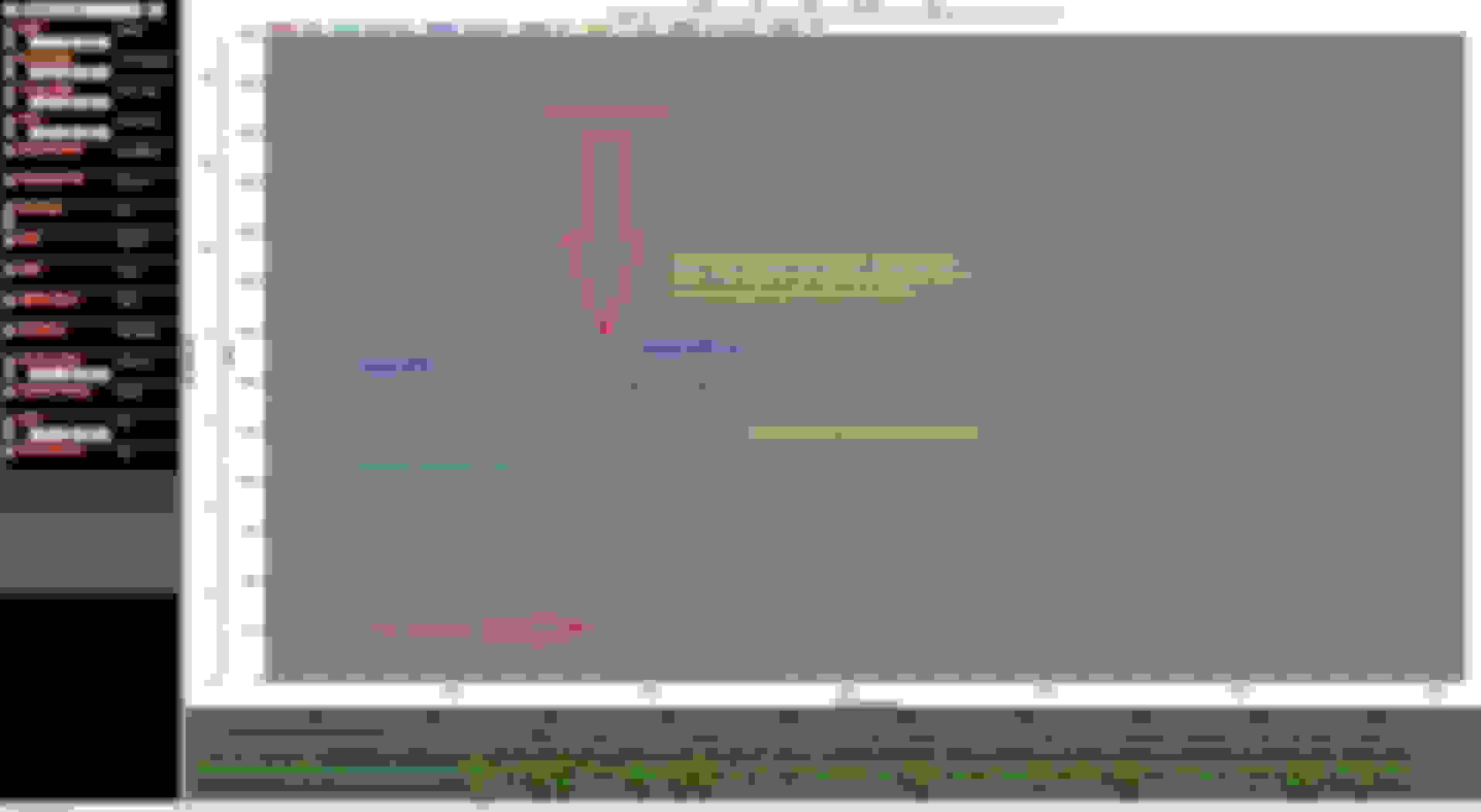
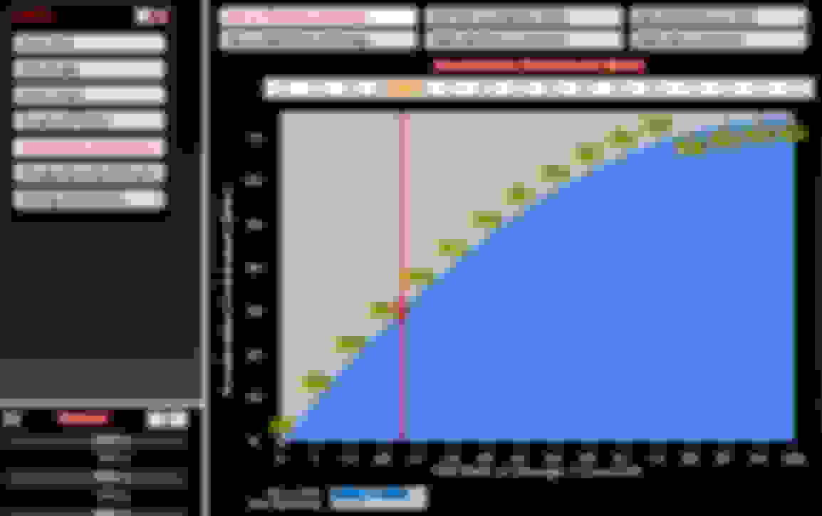
Here is a data log of a deceleration event. The deceleration AFR is actually after tuning it. It was very rich from the wizards tune.
The base fuel graph highlights the area of max vacuum because that area was selected on the data log. The modifications you would make would be on the table, not the graph as shown. I used the graph to illustrate the slight fuel bend towards the bottom of the graph.
You may also notice a hump or hill that forms around the 2500 RPM range and closer to full load on the engine. These are typically acceleration humps often due to driving styles. These are the areas that happen AFTER the AE fades away, but there is still a significant need for fuel in these areas. The affects of AE will be further explained in that section, but you can see the effects on the base fuel table - if you are transferring the learning to base. So during a quick throttle movement the AE kicks in and CLC goes to zero. Fractions of a second later as the driver levels out the throttle position, the AE goes away and the CLC takes over but the engine is still increasing speed. So the CLC recognizes the now lean condition and adds fuel. The learn function recognizes the constant need for more fuel in these areas and alters the base curve. When the learning is transferred to base, the result is a hump in the base fuel curve.
6. TUNING TIPS � CLOSED LOOP COMPENSATION:
Generally speaking, CLC is active once the O2 sensor is heated and through all other engine parameters. CLC is the feedback mechanism for the Sniper ECU to adjust fueling to optimize efficient burn in the cylinder heads. If you get an EFI unit, and don't run the system with closed loop, you are essentially defeating the main reason for EFI in the first place. There may be specific reasons for running open loop, but for most applications you want to be in closed loop for 99.9% of the time. It will make corrections for bad base fuel tables, as well as temperature tables etc... It is a good indicator of how good your overall tuning is. If you are consistently running large CLC numbers (positive or negative) you have tuning corrections to make.
Starting out, you should have large closed loop compensation limits set to allow the software maximum adjustment while compensation for a newly tuned engine. I typically start out with either 100% to 150% when starting a fresh tune. Notice you can modify specific operating areas of your engine. You can also have a + or - condition that differ, if it fits a need.
Remember, CLC is not the same is learning. They work together, but they are not the same. CLC is the direct fuel modification at that point in time to correct the AFR reading. Also keep in mind that CLC is lagging the combustion event ever so slightly which changes with engine RPM and load. High RPM and engine load such as WOT, the exhaust is moving so fast, the CLC is very close to the combustion event (in terms of time). At idle, the exhaust flow is much slower, therefore the CLC is further in time from the combustion event. Granted we are still only talking about fractions of a second, but the sniper will measure down to milliseconds, so when analyzing data, you have to keep that in mind. I like to use about 200 milliseconds to 500 milliseconds as a range of trying to separate a combustion event to when the CLC can respond.
Another commonly discussed topic is "Advanced Control". Advanced Control (1-5) sets how fast the Closed Loop control operates. 1 is the slowest and 5 is the fastest. This depends heavily on where the WBO2 sensor is located in the exhaust system. The further away the WBO2 sensor is (away from the engine), the lower the number should be. If Advanced Control 4 or 5 is selected, one must ensure the ECU isn't oscillating the Closed Loop operation. Viewing a datalog is helpful. Sometimes it's best to start at a lower value, especially with a fresh base calibration. Rule of Thumb: Measuring the exhaust length, 12" from the exhaust port or closer use #5. For every 6" after that subtract one number. For example, if your 30" from the exhaust port use #2. The 1978 corvette with side pipes O2 sensor measures approximately 45�-48� from the exhaust port. Using the �rule of thumb� that would require #1. However, experimentation will get you what the engine needs. Some of that may seem counterintuitive, but in my application, I found that the higher numbers caused a lot of "hunting" or overcorrections. I ended up using a value of "1" and that worked pretty good and fell in line with the "thumb rule".
As an additional safeguard to the O2 sensor failure, consider saving a "LIMP MODE" tune to your SD card. Take your good tune, that has the latest base fuel and all your leaning has been transferred to base. Then go into the closed loop and learn section of your tune and set all the values at 0% to 2% max and minimum values for both the closed loop and learn tables. Save this tune onto your SD card, name it something different than your normal tune names, and leave it on the SD card in case something goes wrong with your O2 sensor. This way in the event of an O2 failure, the sensor may have corrupted your learning table too much to run well. Pull over, load your "LIMP MODE" tune, and drive home. The LIMP MODE tune will still allow some movement of CLC and learn but seriously clamp it down to what you set it at for limits. If you base tune is well tuned, then it will easily get you home where you can diagnose a problem or bad O2 sensor.
7. TUNING TIPS � LEARNING:
Holley Sniper EFI learning is probably the least understood part of the EFI experience. I think the marketing department of Holley did a good job of selling pretty robust expectations. The Sniper system does learn, but only as a modifier to the base fuel table. Also, learning only happens when the engine is warm (>160F coolant temperature), idling, normal driving, mild accelerations, etc... Basically easy driving. So, hard accelerations, engine warmup, decelerations, cranking, air temp changes, coolant temp changes, timing, AFR, none of these things are learned. They are default wizard settings that may or may not be optimized for your specific engine. Furthermore, if you don't manage your base tune, these other tables build off from that further compounding any base tune issues.
As you drive, (and all the requirements to learn have been met), the closed loop compensation system is constantly adjusting the fuel to achieve your desired AFR setpoint for that given engine load. The learn system is monitoring how much fuel (in a given engine load area) is being added or subtracted (due to CLC). It calculates a percentage of added or subtracted fuel in that part of the table that is needed to achieve the desired AFR. That becomes your modifier in the learn table. That value is now automatically added or subtracted from the base fuel table as you move through that area of your engine load. At that time, your base fuel table has NOT changed. Base fuel value + or - learn table modifier = modified base fuel value. Initially, your base fuel table may be significantly off. The learned values may be large percentages (>10%). In order to get your learned values smaller, you must transfer the learned values to the base fuel table. This permanently modifies the base fuel table, but it should be "changing" to better reflect your actual engine needs. After the values are transferred, the learned table clears. Now your Sniper unit is ready to start learning again, but hopefully now it has a more accurate base table. The learning values should start to become smaller as you do this.
Here is an example of a learned table. Notice how the cruising area and the idle area have +4% to +7% added fuel areas. Many of the other cells are less than 1%. There is one particular area that is like a crater calling for -8% or so. Perhaps this is a shift point for easy driving. Typically when I see that, I don't like to transfer that to base as is. It creates abrupt fuel changes in the base curve that you typically don't want. I might highlight all the boxes, => then right click => click "offset selected" => *.5 or 50%. That will half all the values in the learning table. Now transfer those to base. So you still made a tuning improvement, but less abrupt. Your Sniper will then pick up learning with a clean sleight where you can repeat the process and modify your base tune again when convenient.
Learning is another parameter that you should have the limits set to either 100% or greater such as 150% to start your engine learning. I believe that the default numbers may be 50% but I can't fully recall. You can go higher, but if you are that far off, there may be another set up issue to resolve first.
Once you start locking in a good tune, and your learning is consistently <10%, it may be a good time to clamp down on your Snipers ability to learn. Below is an example of adjusting the learn limits to 10% across the board. Now the sniper will only be able to adjust your modifier table by 10% or less.
In addition to limiting the learning max or minimum values, you may also wish to SLOW the rate of learning. To accomplish this you must change the 'Base Fuel Learn Gain' located in the right upper corner of the 'GENERAL' box within the 'Learn Parameters' as shown in the above image. You can experiment with this, but if you cut the gain by 50% you'll easily notice that the system populates the current learn values slower. A good example of an application for this would be as you are clamping down on your learn values. If you clamp down to say 10% learn, but you don't want single digit base fuel adjustments to constantly build up and down due to ambient conditions, slow down the learning so it only learns what is consistently there. It will be less likely to learn abnormal CLC responses. It sort of acts like reducing the rate of change average algorithm for the learn value.
As an additional safeguard to the O2 sensor failure, consider saving a "LIMP MODE" tune to your SD card. Take your good tune, that has the latest base fuel and all your leaning has been transferred to base. Then go into the closed loop and learn section of your tune and set all the values at 0% to 2% max and minimum values for both the closed loop and learn tables. Save this tune onto your SD card, name it something different than your normal tune names, and leave it on the SD card in case something goes wrong with your O2 sensor. This way in the event of an O2 failure, the sensor may have corrupted your learning table too much to run well. Pull over, load your "LIMP MODE" tune, and drive home. The LIMP MODE tune will still allow some movement of CLC and learn but seriously clamp it down to what you set it at for limits. If you base tune is well tuned, then it will easily get you home where you can diagnose a problem or bad O2 sensor.
8. TUNING TIPS � IDLE:
During my initial startup after the Sniper unit had been installed, one of the hardest areas for me to deal with was the idle area. Part of the reason was due to some small vacuum leaks, and an erratic out of the box O2 sensor, but still it was different than setting an idle with a carburetor. The concept of what the engine needs to idle - is the same, but for a carb, you can sort of set your idle by setting apart variables to get your idle correct. Meaning a carb isn't going to change the amount of air it lets in on its own, nor will it adjust timing for the best idle characteristics, nor will it adjust fuel on you while tweaking something else. As you set a carb idle up, you generally set the throttle blades for a certain amount of air then adjust the fuel to maximize idle vacuum based on a fixed amount of air coming into the engine (or similar concept). Depending on your timing / cam etc idle speed has a tendency to fall where the engine needs it to be.
EFI idle doesn't allow the engine idle RPM to fall "where it wants it to be". It constantly adjusts timing, air and fuel to match an RPM that you told it to maintain. So I went from setting my RPM to "where the engine likes it" to "where do you want it to be". The Sniper will try and maintain an idle at the desired RPM regardless if the engine "likes it there" or not. That took some adjusting on my part to get used to. In a way, you still try to find a good idle speed by experimenting, but since the unit is moving other variables to achieve the desired RPM, it was harder for me to dial in.
Target Idle Speed RPM:
Increasing the idle RPM provides a smoother idle. This doesn't mean your engine has to idle at 1000 RPM, however, don't expect a race engine with a radical camshaft to idle at 700 RPM. Generally, the bigger the camshaft the more idle RPM it needs. Most mild performance engines should idle well at 700-800 RPM and most potent street performance engines should idle well at 800-900 RPM. Serious race engines with radical camshafts will need to idle at 900-1000+ RPM, due to the camshaft's tight LSA which causes a high overlap period (not efficient at idle & low RPM). Also, ensure the Target Idle Speed RPM scale is properly programmed. If the hot engine idles in between two temperature cells on the Target Idle Speed scale, set the temperature cell before & after the target idle, to the same RPM; so the ECU doesn't vary the idle speed.
Target Air/Fuel Ratio:
Most high performance engines will idle well with a target air/fuel ratio between 13.5:1 & 14.2:1. This surprised me, and I wasn't comfortable with it at first, because I thought the idle should be leaner at a stoichiometric 14.7:1 AFR. However, when I tried it, my engine responded favorably. This became one of the three most significant aspects of my idle quality improvement (the other two being timing advance & Fuel Table tuning). This isn't as detrimental to fuel economy as one might think, because at idle, there are less injection events (engine cycles) over time, than at higher RPM. Remember to also check the idle in gear, and allow the engine to idle for at least a minute with each change (Automatic Transmission).
Ignition Timing Advance:
First, ensure the ignition timing is synchronized as described in the timing section. The Base Timing Table must be flat in the idle area, meaning it's the same value in the entire idle area (especially if using Idle Spark Control). Most street performance engines will idle well with 15�-25� of timing advance. (Stock cam - 20�, performance cam - 25�, radical cam - 30�). The exact amount depends heavily on the camshaft specifications. Generally, tighter LSA - lobe separation angles (overlap) and larger lobe duration figures, require more timing advance at idle. 106�-108� is considered a tight LSA (idle quality suffers with less idle vacuum), 108�-110� is moderate, 110�-112� is moderately wide, and 112�-114� is wide (idle quality improves with more idle vacuum). One must pay close attention to how much timing advance is used at idle. Resist the urge to use too much; I've made this mistake in the past. Advancing the timing, offers better fuel efficiency and raises the idle speed, however, excessive timing creates an unstable idle speed due to the engine having too much torque at idle (Idle Spark control becomes ineffective). Retarded timing lowers the idle speed, decreases engine torque and increases the coolant temperature. Excessively retarded timing also causes the exhaust headers to glow red hot. Generally speaking when tuning for you optimal idle timing, start with a LOWER base idle timing number than you think you need and work your way up. Too much timing will make the idle timing control too finicky and the changes will have too much of an affect on the idle speed due to the increased torque on the crank. Start about 3-4 degrees lower than your expected idle timing number. Work up from there...
Using the Static Timing Setting for Optimum Idle Timing:
Under normal circumstances the static timing is used to synchronize your actual timing with the desired computer controlled timing (when using Sniper controlled timing). However, there is another tuning trick you can use to try and find the engine's happy place for it's idle. Just like with a carburetor, the best idle usually produces the best idle vacuum. Therefore, when you are done synchronizing your timing control, experiment with static idle timing setpoints. Try 20*, 25*, 30* or even 35*. While doing these tests, have a vacuum gauge connected to manifold vacuum. Adjust the timing settings and observe which timing setting produces the greatest vacuum. Then return to your timing table, and adjust your timing in those areas for the optimum idle timing.
Here is static timing option on the hand held:
Idle Spark Control Tuning:
The Idle Spark Control basically helps stabilize the idle speed by manipulating the timing (quickly increasing & decreasing in accordance to RPM). The idle quality must be well tuned before adjusting these two parameters. If the idle is well tuned (fuel & IAC), the Idle Spark PID control can actually help determine the optimum timing advance at idle. It may help to datalog various P & D combinations (name the datalog by the two numbers to decipher them), and look for the straightest RPM line. This is because you can't watch the idle RPM on the Data Monitor, since they change too fast and the tachometer usually isn't an accurate enough indicator of idle stability. Typically values of 20 or 30 (P term) & 40 or 50 (D term) are a good start with Holley EFI systems.
P & D Definitions - Excerpt from Holley EFI manual:
� Proportional Term � P Term � Speed/gain of the system when there is a large deviation in the target idle speed. Raising this value increases the speed at which the timing moves in order to remove target idle speed error. If this value is too high for a specific application, the timing will oscillate (be out of control), and cause the engine speed to surge up & down. If the value is too low for a specific application, timing will be slow to react to quick changes in idle speed deviation. However, it is much better for this term to be conservatively slow, rather than too fast.
� Derivative Term � D Term � (Derivative) Higher Derivative terms reduce the tendency of idle speed overshoot. Smaller Derivative terms slow down the timing movement as target idle speed is approached. The Derivative Term looks at where the engine is going and where it will be in a half of a second. It doesn�t look at where the engine is right now. For example, if the Target Idle Speed RPM is 750 and the engine speed is 700, but it's rapidly approaching 750, the Derivative Term will try to reduce timing to slow the idle down and keep it from "overshooting" the Target Idle Speed RPM.
Using Idle Spark Control for Optimum Idle Tuning:
Like using the static timing above, another way to optimize idle tuning is to data log your engine in an idle condition. While watching the idle fluctuate (during idle spark control operation) notice the magnitude of the fluctuations. If you can get your fluctuations less than 3* of timing from peak to peak, you have a pretty good optimized timing setting. If you are > than 3* you may have to adjust your timing so your engine is more in a optimal place. Doing this live with a running trend is the best way, but you can always data log the idle and make an adjustment, and re-watch the idle.
In the above data log, the engine is warmed up and idling at around 825 RPM. However, the timing is fluctuating anywhere from 1* to 4* difference. Some of the fluctuations are small 1*-2* at times. There may be some room for improvement here. Perhaps the engine may idle better at 850 RPM with the same timing of 25* (base) with the idle spark control active. Keep in mind, engine speed, cam, fuel tuning can also affect what you see here. However, you can use this as a tool to help dial in a smoother idle.
The below data log represents further improvements on the idle quality of the engine. The below graph represents improvements in idle timing swings (at the most 2.8 degree swings), and RPM fluctuations (plus/minus 25 RPM or less). These improvements were done not by one parameter but by several. The cam for this tune was a 236/242 110 LSA. Idle RPM, AFR target, Idle Spark P&D term, and ignition timing were all adjusted (although not all together), to find the best idle parameters. One thing that I have learned about idle timing and EFI, was to avoid the urge to "over time" your build. As mentioned, this can cause too much torque at idle, which will lead to difficulties tuning the idle. For example, when talking about where to set the idle area of your timing curve, you must consider where your timing was when you operated from a centrifugal advance AND the vacuum advance. I see many folks set the idle area of the timing curve at say 15 degrees advanced - like the carbureted car had. However, was that number correct while your car idled WITH the vacuum advance canister at full manifold vacuum? NO it was idling at 15 degrees + the 12 additional degrees that the canister was adding for a total of 27 degrees at idle! The 2D table of the Sniper represents BOTH the mechanical advance and the vacuum advance together. I have found that with the EFI timing control, the idle area vary rarely needs > 25 degrees TOTAL timing to have a stable idle. Mild cams generally like 18-22, moderate cams 20-24, and more radical cams about 22-26 TOTAL timing. Again these are general statements, and I'd also assume that the other parameters are also dialed in as well.
IAC (Inlet Air Control) Notes:
1) Adjust the idle speed screw on throttle body, to achieve an IAC Position of about 5% at hot idle. Remember to perform another TPS Autoset, whenever you adjust the idle speed screw on the throttle body. In the Idle ICF, the "Target Idle Speed (RPM)" must be programmed to the desired RPM speed at hot idle. Ensure the proper type of Advanced Idle Control is selected in Idle Settings. "Slow" may provide the best idle quality. FYI: Some throttle bodies require a 10% IAC Position at hot idle, to compensate for increased airflow due to further thermal expansion. I've noticed this to be true for my application. I like to set my IAC hot idle after driving where there has been sufficient heat soak in the engine compartment.
2) Opening the throttle blades (idle speed screw "in"), decreases the IAC Position at hot idle. Closing the throttle blades (idle speed screw "out"), increases the IAC Position at hot idle. If the idle speed screw is unscrewed too far, the engine is inhaling air from an additional source - vacuum leak. Blocking off the entire throttle body amplifies the vacuum leak, and it usually makes a detectable hissing sound.
3) Ensure the IAC Hold Position isn't set too high. At particularly low TPS Positions, this can induce more air (> 1% TPS) than some engines need. Ensure the TPS Position always returns to 0% at idle. If not, it activates the IAC Hold Position and raises the idle speed, causing issues. You may have to slightly back-off the idle speed screw (after a TPS Autoset), so the TPS Position always returns to 0%. Ensure your throttle linkage moves/returns freely (hot & cold), and usually a stronger throttle return spring is all that's necessary to rectify this. Over-advanced ignition timing, rich AFR and/or primary throttle blades open too far at idle (idle speed screw) can hinder the return to idle RPM. Also, if the IAC Hold Position is set too high, or the RPM Above Idle To Start Ramp is set too low, the engine RPM will hang & not return to idle.
4) You can test the IAC motor function by changing the IAC Parked Position % (cycle the ignition key off/on after each change), turn key-on/engine-off, unplug the wire connector, remove it from the throttle body, and verify the pintle position (or just look down the IAC passage in throttle body). Try this at 0% & 100%.
5) If blocking off the IAC air inlet port results in improved idle/deceleration operation, then problem is IAC related. If the ECU is commanding 100% IAC Position, it's because the IAC valve isn't increasing the engine speed. Ensure the fuel injectors or spark plug wires (or any other high voltage wiring) aren't too close to the IAC motor/wiring. The IAC motor is easily susceptible to electrical interference, and it'll cause strange occurrences and become inoperable. To eliminate the IAC valve as a problem, temporarily block off the IAC air inlet port with a strong piece of tape.
6) * Initial Baseline Idle Speed Screw Setting * Sometimes the throttle blades are so far off adjustment, turning the idle speed screw triggers the IAC Hold Position. If this happens, the throttle blades will require a baseline setting without the IAC valve altering this adjustment. This must be accomplished with the engine at hot idle. Be careful of dangerous fan and belt driven components. With the air filter previously removed, block off the IAC air inlet port with your finger or a strong piece of tape. While temporarily ignoring the IAC Position, adjust the idle speed screw to the Target Idle Speed RPM (in Idle ICF). Turn engine off (remove tape). With the key-on/engine-off, perform a TPS Autoset. Cycle key off & restart engine. Now only a minute adjustment will be required to achieve an IAC Position of about 5%. Perform a final TPS Autoset.
7) Sniper EFI Idle Setting/Throttle Blade Setting (Holley Sniper EFI Quick Start Manual): Once the engine is up to operating temperature, the idle speed can be set to what was configured in the Wizard. To do this, open up the Initial Startup gauge screen. With the vehicle in neutral, adjust the idle screw until the IAC Position reads between 2 & 10%. While adjusting the idle speed screw, if the TPS Position begins to read higher than 0%, cycling the ignition switch will recalibrate the TPS back to zero.
NOTE: Do not attempt to set the Target Idle Speed and IAC Position until the engine is above 160�F!
8) The idle speed screw/IAC Position relationship should be done in neutral and at hot idle. Also ensure this isn't tuning related. On the Base Fuel Table, the "in gear" idle area is just above the "neutral" idle area. The "neutral" idle area may be tuned, but the "in gear" idle area may not be (automatic). Look at where the live cursor moves to, when you shift the transmission into gear (automatic). Is this "in gear" idle area, a little more rich (lbs/hr), than the "neutral" idle area? You'll have to look at the Learn Table too, since they function as one. Also, ensure the Target A/F Ratio Table and Base Timing Table are flat in these two idle areas.
9) Typical IAC Control/Ramp Down Parameter Settings
Advanced Idle Control: ......................... Slow (Usually the best control.) Sniper EFI users select "Sniper TBI".
IAC Type: ........................................ .. Stepper (4-wire), PWM (2-wire)
IAC Hold Position: ................................ 10%-30% (Usually 15%-20%.)
Ramp Decay Time: ............................... 1.0-3.0 sec (Usually 2.0 sec.)
RPM Above Idle To Start Ramp: .............. 1000 RPM (Or higher.) (Automatic Transmission) 300 RPM to 700 RPM (Manual Transmission)
RPM Above Idle To Re-enable Idle Control: 50-200 RPM (This setting can be finicky.)
Startup IAC Position - Hold & Decay Time: 1.0-1.5 seconds (Less is typically better than more.)
Not IAC, but Idle Spark control usually works well at: 30-40 P Term & 50-60 D Term.
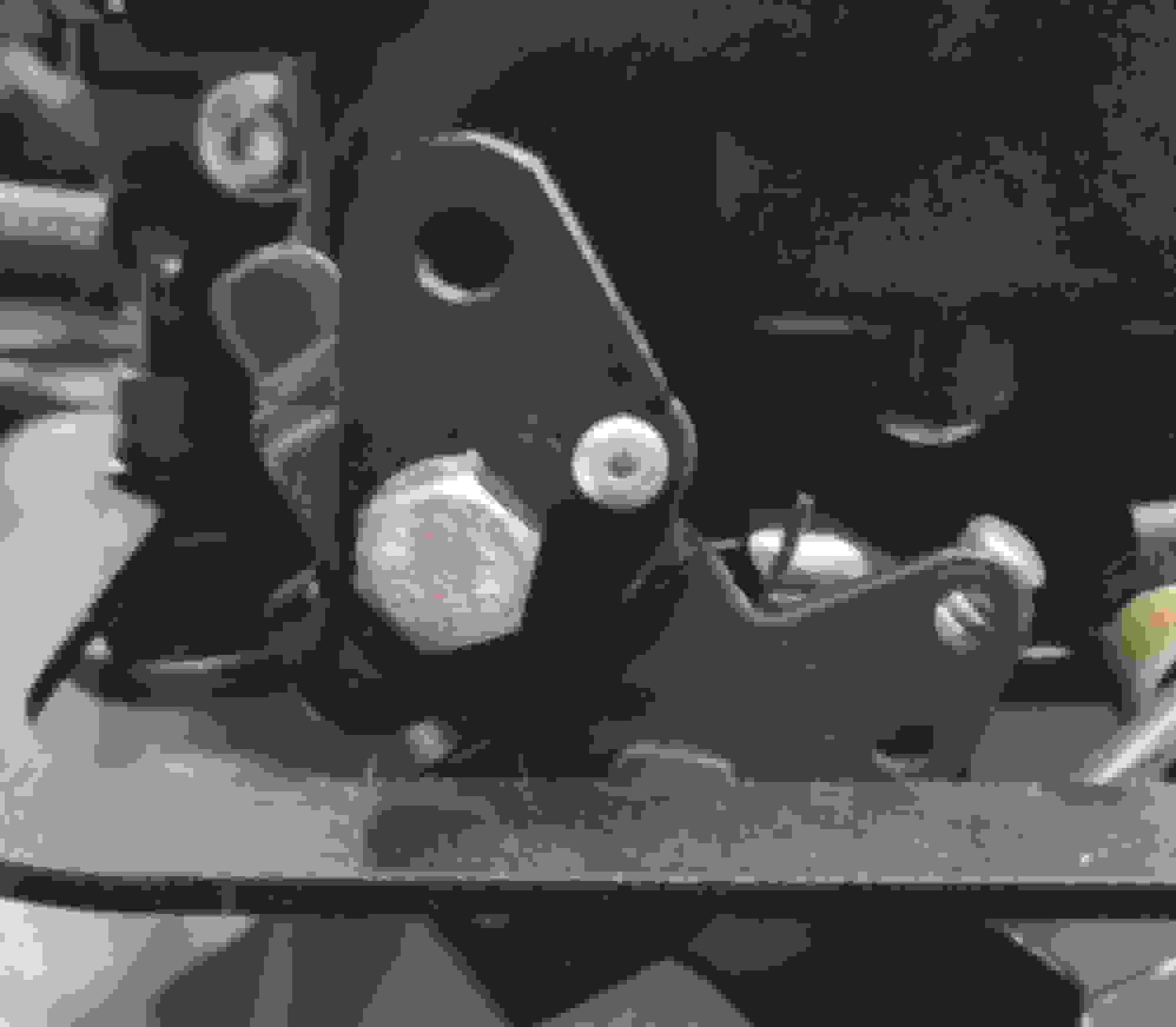
Location of the Idle Speed Set Screw:
IAC Ramp Down Settings:
The IAC Hold Position is the setting where the IAC will sit when you are doing your normal driving. Generally speaking, the lower the setting the better (10%-20%). Setting the IAC hold too high won't allow you to transition from a "driving" condition to an "idle" condition. It will allow too much air into the engine while the throttle blades are at rest (almost closed) resulting in your engine not returning to idle. Setting the value too low won't allow the Sniper to "ramp down" to idle smoothly resulting in the unit having to "catch" your idle before stalling out. This setpoint will have to be "tuned", find out what your engine combo likes best.
The next three IAC Ramp Down Setting values work together to transition the car's engine from a running condition to an idle condition. RPM Above Idle to Start Ramp is sort of what it states. Ramp Decay Time is the time the IAC will move to transition from the RPM Above Idle to Start Ramp to actual idle control. The RPM Above Idle to Re-enable Idle Control is where that actual transition takes place.
For example:
Using the above illustration, and an idle RPM setting of 825 RPM: While driving the IAC position would be 15%. The driver then takes their foot off the gas to decelerate at a stop sign. When the TPS = 0%, AND the RPM reaches 1325 RPM (825 RPM idle + 500 RPM Above Idle to Start Ramp) the IAC will start closing to transition from 1325 RPM to 925 RPM (825 RPM idle + 100 RPM Above Idle to Re-enable Idle Control). It will try and maintain a 2 second ramp as defined by the Ramp Decay Time. At 925 RPM, the idle control will take over, and the IAC will move to maintain idle at 825 RPM (as well as timing control if enabled).
It's important to note, IAC Ramp Down has to be tuned differently for automatics and manual transmissions. Specifically the "RPM Above Idle to Start Ramp". If you set that value too high for a manual transmission, the IAC ramp will happen before the clutch is depressed, so the engine will decelerate with the drive train. The IAC isn't controlling RPM at all at that point. Then when the clutch is depressed, the IAC is closed (because it is trying to slow an engine that can't be slowed with less air while the clutch is engaged) resulting in an uncontrolled transition from running to idle. Therefore, for a manual transmission the "RPM Above Idle to Start Ramp" must be set at an RPM just below where you would normally depress the clutch. For most people that would be somewhere around 1100 to 1500 RPM depending on your driving style.
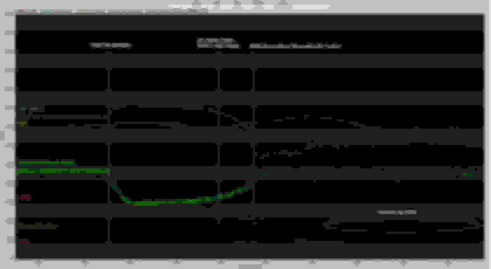
Below is an example of a transition to idle problem. We can't draw simply one conclusion from the data logs below, but you can clearly see that the transition to idle wasn't good. The IAC goes completely closed during the ramp down for one. In other words the EFI unit isn't controlling engine slow down. That could be due to a vacuum leak, PCV problem, improper throttle blade settings, clutch engagement, or bad tuning (IAC specific). Notice the drop in timing as well. The EFI unit is TRYING to slow the engine down, but cannot.
The following is an example of a "smoother" transition to idle control to contrast it with the above data log.
9. TUNING TIPS � TEMPERATURE ENRICHMENT:
There are three components of the temperature enrichment. For tuning purposes, only one of them is really needed to be tweaked significantly: Coolant Temp Enrichment. So, we'll deal with that one first. Air / Fuel Ratio offset I only use when the engine is cold. I essentially tune it out at any coolant temperature above 70F by simply zeroing the chart. As the engine gets cooler than 70F I subtract .1 AFR from my desired every 15F or so. This chart to me is sort of redundant, to tuning the coolant enrichment table. However, if you ran into a situation where the engine just didn't want to run correctly at a certain AFR and coolant temperature, than you could modify that here.
The Coolant Temperature Enrichment should be dialed in before the other temperature enrichments. Since air temperature doesn't modify the fuel as much and varies little while you drive, it is more desirable to start with coolant. This part literally took me months, especially the cold start tuning. Obviously when you are tuning in the cooler areas of the coolant temperature, you only get one shot per day or at least a bunch of hours between starts. Warm starts or hot starts are easier to tweak in, because you can repeat them relatively quick. In order to tune your coolant temp enrichment, you must use data logs (which your really must use for most tuning anyway).
Here is an example of a tuned coolant temp enrichment table:
This enrichment table is also a multiplier to the base fuel table. Therefore 154% is 1.54 x the base fuel table, or +54% however you like to do your math. The way you tune a start (cold or hot) is to trend the rise in coolant temperature over the startup and observe what your closed loop compensation is doing. If it is consistently adding fuel like +15 percent in a certain temperature range, that means your base table needs some help at that temperature range during a warmup. The idea is that your tables are tuned well enough so you MINIMIZE the amount of CLC that has to take place at any given coolant temperature. How much to adjust the graph can be done different ways.
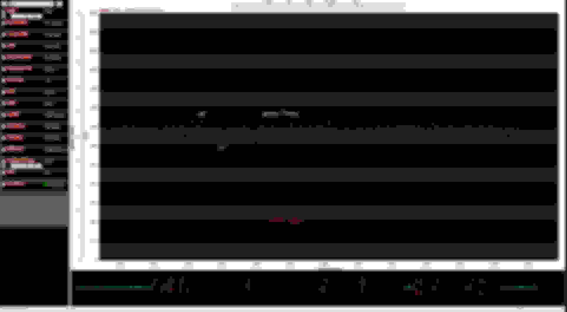
The following was an image of a cold start (from 45F) until engine was in the normal operating band.
First off, MAT (the pink unmarked line) isn't much of a factor to tune during a startup. It doesn't change significantly or add that much fuel to worry about tuning. Secondly, this was a pretty good tune. Notice that other than the first 100 seconds, the CLC stayed within a + or - 5% during the whole engine warmup. That would tell me that the coolant enrichment table for that application was pretty well tuned in those temperature ranges. If the CLC was trending around 10% or greater, there would be some room for improvement.
Methods of tuning the coolant temp enrichment: one way is scientific, the other is simpler but relatively effective. The simple way, take the given area at that given temperature where your CLC needs reducing (of its value). For example your CLC is about -18% at the 40F area of your table. Divide 18 by 3 (or 4 if you want to be conservative) which gives you 6. In this case, your CLC is subtracting fuel, so you would reduce your graph by 6% @ 40F. Then you do another cold start and validate your new data.
Or you can use a fancy spreadsheet which does some fancy math to arrive at a more precise answer - and adjust your curves from there. Notice the scientific way came out around 5.4% which is pretty close to 6%. The spreadsheet even tells you what your new number should be. As you can see, depending on your engine combo, the coolant enrichment may be significantly different than the Holley default tune, mine was. Will it work, yes, because CLC will compensate for the tables. However, if you want to tune that and make it run well WITHOUT a lot of compensation, tune that thing!
Air Temp Enrichment is needed and used, but setting it up is pretty easy. The out of the box Sniper table could be used. I have experimented with different values. It's important to note, air density changes are not perfectly linear, but close enough for car tuning purposes. If you do an actual air density calculation, it comes out to about 2.5% correction in fuel for every 15F change. I found that curve to be too aggressive, so I dropped the temperature correction to about 1.5% for every 15F change. The only other concept to discuss is where to reference the "breakpoint" or "zero adder" point. Mathematically, it doesn't matter, because the engine cares about the CHANGE in fuel from one air temperature to another, not the actual value. (If you have your base fuel table tuned well, and then change this table, it will re-adjust your base table based upon changes made here.) Most tuners advise placing the breakpoint in areas where your inlet temperatures typically are. That works as well. Simply put the breakpoint in the middle of the table, which also works.
Another method of tuning the Air Temp Enrichment I like to use was the "dead band method". Actually, it's not really called anything, but I had to reference something. First, establish a 20F area where your MAT stays most of the time in the normal driving conditions for your car. Then, zero out that area, meaning 100%. The Sniper is neither adding nor subtracting fuel in that area. It doesn't have to be a 20F range, it could be 15F or 30F depending on your temperature scale. Remember, before you start messing with any of the other modifier tables, you must have a good base fuel table for normal operating conditions. The trick to tuning the air temperature enrichment tables is having that differential in temperature to make comparisons. For example, driving in the cool morning, then driving again during the warm afternoon. Then, from the edges of the 100% zone, establish a linear table extending to the coldest temperature. That side should have a positive amount of fuel added, or greater than 100%. I usually start out conservative and add about .1% / 1 degree F. Do the opposite to the right of your dead band. Subtract .1% / 1 degree F.
Now overlay the two data logs of a morning drive and an afternoon drive. Compare the MATs. Also compare the "current learn" data. The numbers will fluctuate, so keep an average in mind. Lets say that during your warm base line drive your current learn averaged about 1% of added fuel. I consider that basically nothing, but compare that to the morning or colder drive. If the MAT was 74F on the morning drive and 101F on the afternoon drive, and the morning drive generally wanted to "learn" a +4% average value during the drive, then you need more fuel at the 74F MAT point. I wouldn't recommend that you add the whole 4%, remember, that was an average. I might build my new linear graph to add another .5F or 1F in that area while still maintaining a linear curve. So don't feel the need to overdue it. It's not the only input on your fueling. Then duplicate that linear graph on the hot side of your 100% dead band.
The below table was a snap shot of two different driving conditions in terms of MAT. Although the amount of learning that was done for the whole drive varied the % learn, the general trend was a greater need of a little bit of fuel during the colder drive. So, adjusting the MAT enrichment up just a little bit would help maintain a better fueling for the cooler MAT. Again, these are averages, so avoid the urge to add 3% in this area. I usually move in .1% to .5% per degree F moves to avoid an overcorrection of fueling. Even using .5% / deg F is fairly aggressive. A 3 degree F move in the MAT would result in a change of 1.5% fuel change.
Once you get the air temperature enrichment dialed in, the desired affect is to see minimal CLC changes and learning changes no matter how the temperature changes in the ambient.
10. TUNING TIPS � STARTUP / CRANKING PARAMETERS:
You can spend a lot of time dialing in the Sniper's startup / warmup parameters. Cranking parameters are a little bit easier to deal with. Further below, but still in the "startup / cranking parameters" you'll find some notes / guidance on how to dial in your startup. I found that the startup tuning notes below to be pretty efficient at dialing in a good efficient startup. I like to shoot for a time of sub 1 second from key / crank to run (> 400 RPM). Another great tutorial on tuning a startup can be found on EFI Systems Pro website. Follow the link provided for a good example of startup tuning. They are a great source of technical help and in my opinion - better than Holley.
Inside the "Spark" dropdown you will have the "cranking parameters" section. Here you can define the timing while cranking and the RPM in which your Sniper transitions from cranking to "running" modes of control. I generally only define the timing, and I usually leave the transitional RPM of 400 alone. However, your specific engine combo may do better with other configurations than shown below:
IAC Parked Position
The IAC parked position determines the position of the IAC when an engine is cranking and immediately after it starts. Generally speaking this table isn't critical to tune, and the out of the box values will generally work. However, you can tune it, and you probably will find that there is room for improvement for your engine build. You'll notice that right before your engine is cranked to start, the IAC is at some general position open. That is the parked position. It also stays parked until the engine fires, and it transitions to idle control. Park position is coolant temperature dependent, just like your idle RPM speed is. The best way to tune this parameter, is to data log various startups. Compare the starting parked value to the actual value of where the IAC goes to - to maintain your desired idle RPM at that coolant temperature. They don't need to exactly match, but if your parked value is 50% at a certain coolant temperature, and the IAC goes to 85% right after startup in idle control, then your parked position is probably too low and should be adjusted up some to closer match where the engine wants to be anyway.
There really isn't any disadvantage to having TOO much air upon the initial startup. Your initial flare up may be high, but the engine will settle back down due to your hold time and decay time. That parameter is found in the 'Idle ICF' under IAC settings. See the image below. You can however, adversely affect your startup by having TOO little air. The general tuning practice here is to start higher than normal and work your way down in relatively small IAC % increments (at the given temperature breakpoints) until your hold position is where you want it. Be careful - while tuning this parameter - to resist the urge to take away too much air. It is better to have a slightly higher 'flare up' then to lose startup efficiency due to lack of air. In my experiences, the flare up was better controlled with the hold time and decay time.
Here is an example of a tuned IAC Parked Position table:
In the following data log, you'll notice that the IAC parked position is a straight line at the beginning of the engine start. Once the engine starts, the IAC position closes a little (very quickly) but then opens up to a new value that decays away over many seconds. For this example I'm using two separate tuned tables. They are good examples, but I don't think they corollate with each other. The point is, not to look at actual values, but the concept of tuning the table. In the data log below, for a starting CTS of around 50F, the original IAC parked position was tuned to initially start at a slightly higher value - because that's what the engine wanted anyway. So I probably modified my "parked table" to more closely reflect the IAC position at 50F according to the data log. For the warmer starts, I generally shoot for a value slightly higher than the ramp down position as seen in the data log below. If you do enough startups at various starting coolant temperatures, you start to get an idea where your engine wants the IAC to be. As you tune that table, the IAC moves less and less after startup because it is more or less already parked in the correct place. Colder starts can be more finicky. The IAC parked position should be higher than the RPM position, but remember your RPM will be higher when colder, and you will be delivering more fuel as well. I would typically default much higher on the startups less than 70F ambient and establish fuel needs first, then circle back to the parked position for colder starts. More air is better than less and that is especially true for colder starts.
Notice at around the 6 second mark the AFR starts trending rich, but the CLC starts removing fuel to counter the richness. That could be due to the after enrichment tuning, or it may be still a case of too much initial fuel from the prime or cranking fuel. I've lowered the after start enrichment before only to not correct that over fueling after engine light off. Once I trimmed the prime and cranking fuel to "just enough" that rich post start goes away, then you can tune any leanness out with after start enrichment.
Fuel Prime Shot:
When you turn the ignition on (before the crank starts) the Holley Sniper powers up, primes your fuel pump, and injects a splash of fuel into your intake manifold. That action is the carburetor equivalent of giving your pedal a pump before startup. It is supposed to 'wet' a dry manifold. That all happens before the actual crank, which is the next part of the process. Holley calls that the "fuel prime" and as you can note below, it can be turned off. I don't normally turn that off, but I believe it has to be tuned for your application. The default is 150%, but that number works with the "fuel prime multiplier" which defaults to 5. The way these things work together is based upon coolant temperature at the time of startup. The multiplier is at the maximum at -40F and is 1 at 160F coolant temperature. So it acts as a linear multiplier in between those ranges. So, I typically lower my prime number to say 100% but INCREASE my multiplier for colder temperatures. For example, 100% and a multiplier of 7. I didn't randomly select those numbers, I watched my data logs of various starting conditions for that specific engine build. Specifically, the time it takes from crank to engine fire. That gives you an idea of the efficiency of the start. If you can get your car to turn over in 1 second or less from key turn, you have a good efficient startup.
The amount of fuel that the prime shot delivers is based upon four things for the Sniper platform: coolant temperature, cranking fuel (at the coolant temperature), cranking fuel percentage, and the fuel prime multiplier. The cranking fuel is the base number referenced to the cranking coolant temperature. The cranking fuel is then multiplied by the cranking fuel percentage. At any coolant temperature above 160F the multiplier is 1. The multiplier then changes from 1 @ 160F to maximum (depending on settings) @ -40F. The reason it is important to understand this, is because if you change your cranking fuel, you will affect your prime shot as well. They are not exclusive to one another. They are multipliers to one another. For example, in the below table, we'll use 60F as our starting coolant temperature. That number is 50% of the full scale of the temperature multiplier or 200F x 50% = 100F. Therefore 160F - 100F = 60F. The cranking fuel at 60F is about 39.2 lb/hr on the table below. Therefore the fuel prime shot for that start would be 39.2 lb/hr x 100% x 3.5 = 137.3 lb/hr OR 350% of the cranking fuel for that temperature. So, if you change your cranking fuel table, you will change your fuel prime shot as well. Say you lean your cranking fuel out by 20% across the whole table. So the 39.2 lb/hr becomes 31.4 lb/hr. If we re-do the math, the new effective fuel prime shot would be 109.8 lb/hr. That is an equivalent to a 20% drop in the fuel prime due to the change in the cranking fuel. In summary, if you change your cranking fuel table you will affect the fuel prime amount. However, changing your fuel prime does not affect your cranking fuel amount.
In the following spreadsheet, it you will notice the differences in the fuel prime shot from one table to the next. The first table is a custom tuned fuel prime shot, and the second table would be the default wizard setup based upon that particular engine with default cranking values. Pay particular attention to the fuel prime equivalent fuel rate numbers. You'll notice that although the fuel prime multiplier may be drastically different at a given temperature, the fuel rate may be close to the same value. That was because the cranking fuel was tuned differently from one tune (table 1) to another tune (table 2). That in turn affected the amount of fuel prime shot.
So, we have the before cranking "prime", then the act of cranking. Cranking fuel is the fuel added while the engine is cranking, but before it "catches" or exceeds the defined cranking RPM transition. I usually leave this graph alone - unless the engine is immediately lean or rich while observing the first few seconds after start. Remember, it's also temperature dependent. For me, it was always the parameters AFTER the fire up that needed adjustment, not the cranking fuel. Generally speaking, if your prime shot is well tuned, the engine will fire off with barely enough time to activate the cranking fuel. Cranking fuel can be further fined tune to eliminate the after fire lean or rich condition. Just remember that the cranking fuel and prime shot work together to efficiently start the vehicle.
Some engines start efficiently straight off the wizards tuning parameters. Some do not. Some may start well when warm and others won't start well when it's a cooler dry manifold. The biggest problem when trying to tune a cold / dry start is that you only get one shot at it. Even if you turn the car off after a startup, your manifold is not 'dry' anymore, and the start will be more efficient because of that. Also, the AFR reading may be unstable or inconsistent during the first seconds of combustion. This can lead to mis-reading the data log on what your engine really wants during a startup.
I have read about and heard others mention some inconsistent information regarding cranking fuel. Some have said that cranking fuel has no fuel pump activation, and others have said that the fuel pump is active during the cranking period. Well, I too was curious, and it seemed to make absolutely no sense to NOT have pressure during the cranking phase of the startup cycle. So to finally resolve that issue, I added a fuel pressure sensor into my Sniper input and finally solved the puzzle.
As you can clearly see, the Sniper turns the fuel pump back on when it detects RPM - even before the engine registers cranking speed of around 150 RPM. This will allow the cranking fuel to be delivered.
After Start Holdoff / Enrichment / Decay Rate all work together. I've not noticed a big difference in adjusting the After Start Holdoff for my application. I tried 100 msec, 250 msec, 500 msec, and 750 msec. I didn't really see any significant change in my post start tuning parameters. I set it at 500 msec and left it there. Now After Start Enrichment and Decay Rate do make a difference. After Start Enrichment is a modifier of the base fuel table in percent based upon the engine starting coolant temperature. However, it starts to decay immediately based upon the After Start Decay Rate. For a normal startup sequence: The ignition is turned on => fuel prime => ignition to crank => cranking fuel injected => crank happens => engine starts => Base Fuel Added + Coolant Fuel Modifier + After Start Holdoff Time => Base Fuel + Coolant Modifier + After Start Enrichment => Base Fuel + Coolant Modifier => Base Fuel. That would be a startup fuel sequence for the Sniper, which is demonstrated in the graph above.
Notice in the example below, the initial coolant starting conditions circled in red.
If in this example, the engine was started at 40F coolant temperature. You can see that the After Start Enrichment would add 65% (remember 100% of your base fuel table is your base fuel table value) and it would do it for 45 seconds. However, it DECAYS to 100% over that 45 seconds in a linear fashion. So 22.5 seconds into the decay you would be at approximately +32.5% of your base fuel value due to this particular enrichment. The biggest reason for After Start Enrichment is to add a little bit more fuel to get the engine stable while the base fuel table and coolant enrichment can take over a more predictable fuel need.
I usually start tweaking with startup enrichment once I have the coolant enrichment dialed in pretty good.
Startup Tuning Notes:
OBSERVATIONS:
1. Fuel pump activates when key on to deliver prime shot and bring system to pressure. It reactivates during cranking when the Sniper detects engine RPM.
2. Cranking Fuel and priming fuel was overly rich out of the box.
TUNE HOT START FIRST:
1. Determine your desired AFR command and set it. Just get the car running. Once running, drive it to get a large portion of your Learn Table filled in. Repeatedly drive and apply your Learn Table until you're within maybe 5% correction. Ensure IAC is around 5 to 7 at hot idle.
2. Let engine cool so when you restart, you will be at at 160�F.
3. Attempt to restart, key on for more than two seconds to ensure Prime Shot is delivered. The goal is for the engine to bust off near immediately when you hit the switch. If no combustion occurs, pull your fuel pump fuse (to avoid a 2nd prime shot while programming), make a large adjustment to Priming Fuel %, e.g. 150% to 100%. Reinstall fuel pump fuse and wait about 15 minutes for intake to dry out. Repeat if it doesn't start, but add 50% e.g. 150% to 200%. This will quickly tell you if you have too much or too little priming fuel. By repeating this 3 or 4 times, you can narrow down your priming fuel % to where the engine will fire immediately. At this point do not be concerned if it doesn't continue running at this time. Focus only on that first flip of the key and near immediate combustion. Once you establish this above 160�F CT, DO NOT adjust priming fuel again. Now lets move to cranking fuel above 160�F.
4. If the engine fires immediately then immediately shuts off, most likely you need more Cranking Fuel. If it stumbles it could be too rich or too lean, but most likely, too rich. Make a large adjustment to Cranking Fuel in the temperature range e.g. 5 % of current value. **Remember that cranking fuel affects the fuel prime shot**
NOTES: The goal, immediate combustion and reducing cranking time as much as possible. If you have an RPM flare that is 1500 RPM or less after start, ignore IAC Parked Position adjustments for now. If above 1500 RPM flare, lower IAC Parked Position in the temperature range by 2% or 3%. Just get it below 1500 to avoid it being too high. Hot start is easily repeatable to get tuned first. Less time for engine to cool a little, less time for manifold to dry back out, and this sets the basis for priming and Cranking Fuel in colder temps.
COLD START TUNING:
1. Use an infrared thermometer and check engine temperature where you have your temperature sensor located OR disable the fuel pump from energizing and simply read your current CTS temperature. Let the engine cool for a while and target 130�F. Try to start. Following the same process above if the engine busts off right away, that means your Fuel Prime Multiplier is perfect at that temperature, but at 130�F, it has little effect on actual prime shot delivered. As above, if it busts off immediately then stalls immediately, add more Cranking Fuel. If it stumbles, pull a little out or add a little. You will begin to see my pattern here.
2. Let it cool down longer and target 100�F for your restart attempt. If it does NOT bust off right away, ONLY ADJUST THE FUEL PRIME MULTIPLIER, NOT PRIME PERCENT. Adjust multiplier so that it cranks immediately. Once it does, move to Cranking Fuel.
3. Let it cool down to 60�F and repeat above. Continue until you're at your lowest expected starting temperature.
Once all these steps are taken, you can now trim your IAC Parked Position and After Start Hold and After Start Enrichment.
1. Start with IAC Parked Position to dial in RPM flare after startup. A little bit of RPM flare after cranking is good. Adjust only in small amounts (1 or 2) until desired flare is achieved.
2. Any failure to continue running before the After Start Hold Time, has nothing to do with After Start Enrichment. It only activates after the hold off time. Do not rely on After Start Enrichment to balance out a stumble that occurs before it's activated. Use your datalog to find the balance.
3. Once all that is done, when doing a cold start, put the system in Closed Loop at all temperatures, BUT set Learn Temp to 160�F. Watch your live datalog showing Closed Loop Comp and coolant temperature. While the car is warming up, adjust your Coolant Temp Enrichment live so that your Closed Loop Comp is within five at the temperature breakpoints. Now, your coolant temperature enrich is dialed in. From there, you can use Temp Offset to determine best AFR for those temperatures and let the system do the work.
IN GENERAL:
1. Use Priming Fuel to get immediate combustion when hitting the switch.
2. Use Cranking Fuel to keep it running until After Start Hold Off activates. **Cranking fuel affects fuel prime shot**
3. Use After Start Enrichment to stabilize the engine while the other modifiers can take a more predictable role once the engine is running well.
4. From this point, you can refine but make only VERY small adjustments.
Using the above tuning technique, here is an example of how to analyze your startup efficiency: Remember, since the CLC doesn't usually come into play until some seconds after the start, your AFR will be determined by your IAC hold position + cranking fuel (and some of your prime shot fuel burn-off). In the example below the startup was pretty efficient. The AFR could possibly be improved, but it is always a balancing act between a good startup and not a good startup. I like where the prime fueling is in this example, perhaps I can remove a little cranking fuel to reduce the "richness" post startup.
After reviewing different startup trends I noticed that my engine would generally start easily with about 100% - 115% prime during a hot start condition. It would start with the 150% stock fuel shot as well, but it had a tendency to be rich after the startup that way. However, I had to increase the fuel prime multiplier to get the fuel prime shot adequate on colder starts. What I ended up doing was developing a spreadsheet that would allow me to see the effects of changing the fuel prime percentage with the fuel prime multiplier. The screenshot below was an example of comparison numbers vs the original Sniper default setup.
So by using the above methods I could dial in my hot starts, yet also ensure that I had the right prime fueling at colder starts as well.
11. TUNING TIPS � TIMING / IGNITION:
If you are utilizing the fullest capability of the EFI system, you will also have the EFI system control your timing. People that are committed to making the switch to aftermarket EFI systems should absolutely also switch to EFI controlled timing. You can obviously make it work without it, but you are basically reducing the overall capability of the system significantly. However, in order to have the EFI control your timing, you must have the appropriate distributor and ignition equipment. That can be done in different ways - such as the Hyperspark System or Holley Dual Sync System. It can also be done with a locked out distributor and CDI box / coil, but that will require a more complex setup.
When developing your timing tables, you can simulate the exact timing you need that covers both vacuum advance and your mechanical advance. Think of the curves X axis as mechanical advance, and the Y axis as both engine load and vacuum advance. There are numerous You-Tube videos on how this works. I have a description further below that describes how to set up a more accurate timing table for your application.
Notice in this table, the idle area is flat. That is because in this area, you don't want your timing to fluctuate as your vacuum does. This is more extreme if you have a more radical cam. So I typically flatten out my idle area so the ECU isn't chasing around a changing idle timing number. The rest of the curve should be a smooth transition from one operating area to another, no harsh transitions.
Here is the same timing table in 2D. To set this up, see below. Then it takes some experimenting to smooth the appropriate parts to get the curve perfected.
To create a good flowing timing table that simulates all of your needed engine information, perform the following:
� Go to the �basic timing table�.
� To simulate the mechanical advance, select columns from the base RPM to the RPM on which your timing advance will increase (your base timing). Example Base Timing: 15 degrees. Then select the columns that your max timing advance curve (total timing) RPM to the end of the graph. Example Total Timing: 32 degrees. This gives you three column regions of simulated mechanical advance. Now highlight the first column of the base timing, and drag to the first column of the total timing. Select �fill row values� to integrate the two areas together. This completes the mechanical advance portion of the graph.
� To simulate the vacuum advance, the bottom rows are selected based upon the max timing that would include the max vacuum advance. Use -6 psi to -12 psi. Max vacuum advance: 12 degrees. This would include the area of idle timing. Within a 1 � 1.5 pounds of 0 psi MAP, highlight this row and select down to the first row of the max vacuum advance row. Select �fill column values� to blend the two areas of the graph.
� To simulate the timing reduced for forced induction, reduce the amount of timing necessary after 2500 RPM per pound of boost. Blend this with the rest of the graph. Use the �offset� option and reduce the timing at the desired amount per unit of boost as you work up the chart.
Here is the "building timing tables" step by step using visuals:
Step 1: Clear the timing table
Step 2: Build the the "mechanical advance" of your timing table.
Part 3: Complete the "mechanical timing table".
Step 4: Building the integrated vacuum advance timing graph:
Using the above technique you can generate a 2D timing table that incorporates both the traditional mechanical advance and the vacuum advance in one dynamic table. Generally speaking you should avoid large step jumps in timing if possible - keep the table relatively smoothed out.
There are some other methods to generate good timing tables. I found this great spreadsheet that (someone on the Holley Forum created) that takes all of your known mechanical / vacuum distributor information and creates an EFI timing table based upon that. So if you know all of your mechanical distributor data, you may want to use the spreadsheet, then simply cut and paste into your timing table. Below is a screenshot of the table.
You enter in your known distributor data in the green fields to the left. The spreadsheet then modifies the timing numbers in the table. It even addresses the scaling - except for positive pressure. That wouldn't be hard to manage, you could re-scale the table to fit your needs, then add the boost areas of the table.
Mechanical to EFI Timing Table: See the attachment at the bottom of post #1.
Once you have your timing tables created and ready, (as well as the rest of the config file), load it to the Sniper's ECU. However, you are not done.
Synchronize Timing:
Syncing timing involves ensuring that the timing you have commanded with the Sniper is the ACTUAL timing that the engine sees at all RPM, as seen on a timing light. Syncing the timing should be done for both low RPM (by twisting the distributor) and high RPM (by adjusting the Inductive Delay). When you set up your HyperSpark, you likely used the plastic cap. The cap gets you pretty close, but won't be exact. Normally there will be some small (5 degrees or so) adjustments that will have to be made to synchronize actual timing with the computer timing.
If you no longer have the plastic cap, you don�t need it. You just need to reference the #1-cylinder tower on the base of your distributor. Rotate the engine so that the timing mark lines up to 30 degrees BTDC. Then install the distributor and align the base so the rotor tip aligns with the mark you made for #1-cylinder tower. That will phase the rotor close enough to start the engine and synchronize the timing as described below.
The way that you do this is by setting the timing to a "Static Timing" of 25�. By doing this, the Sniper is telling the engine that, no matter what RPM you're at, the timing commanded needs to be 25�. (You can actually set the Static Timing to any value you want to. 25� works well because most engines idle well at 20-25� and can still rev freely to 3,000-4,000 RPM or so at that value. You will see the importance of that in just a few.)
So you crank up the car, get a steady idle. Then go on your handheld and go to �Tuning� => �System� => �Static Timing� => enter the value (25 in this example) => �Set�. This Static Timing overrides the base spark (and any other spark settings) ONLY while it's open. Meaning you need to keep that screen up while you're checking the timing sync. If you move to another screen, the Static Timing is turned off and the engine goes back to the other spark parameters. So, with car running, set the slider to 25�, then click "Set". Now, leave this screen open, and go check the timing with your timing light. It should be dead on 25�. If it's not, loosen the distributor hold-down and rotate the distributor until the timing light reads dead on at 25�. Tighten the hold down and check it again. Once it reads 25�, you're good. At this point, the Sniper should be commanding the timing that you programmed into it. If you set the Static Timing to 15�, the engine timing checked with a timing light should also read 15�. If you change it to 30�, the balancer should now read 30�.
There is another part of the timing synch process. At high RPM, when the ignition system is taxed harder, variations in the coil, distributors, wires, plugs, etc. may cause the timing to "drift", either advancing slightly or retarding slightly. This indicates that you need more or less "Inductive Delay". So set your Static Timing back to 25�. Go back and point the timing light at the engine. Rev up to 3,000 to 4,000 RPM. You should see the timing "drift". Most of the time there will be some sort of difference although it may be small, usually in the 2-3 degree range.
So you need to have set the Static Timing back to 25�, then rev the engine up to 3-4k RPM, and watch the timing to see whether it advances or retards, and by how much. If it retards, press the back arrow on the screen, and then click "Spark". On the option that says "Inductive Delay", click it and bump up the Inductive Delay by 20 (from 100 to 120, for instance). If it's advanced at higher RPM, lower by 20 (from 100 to 80, for instance). Then go back to the Static Timing screen, set it to 25� again, and repeat the check. Do this back and forth until your engine timing (as checked with the timing light) stays at the timing you have commanded in the "Static Timing" screen. In summary, lower the inductive delay to reduce timing, and increase inductive delay to increase timing back to the static reference timing number.
For example, start off changing the Inductive Delay by 20. The inductive delay was at 100 and it was retarding at 3-4K RPM. It was bumped up to 120 and it was still retarding a couple degrees. The Inductive Delay was changed to 140. But then it was advancing by a degree or two. Reduce the value to 130. But then it was retarding by a degree, so, 132. It was still retarding, just a hair, now to 133. Revving freely to 4K RPM indicated the exact 25� that I had programmed into the Static Timing.
Rotor Phasing:
The Sniper's software is derived from Holley's upmarket EFI systems that (can) use a crank sensor to trigger the ignition. That's where the "reference angle" comes from: It tells the Sniper how many degrees before TDC your crank sensor is installed. As you can imagine, you can simply turn a crank sensor to any setting you desire, so making this freely configurable makes sense.
Only - the Sniper does not use a crank sensor, but the trigger inside a distributor. Thus, each time you change the reference angle, you have to turn the distributor accordingly as both the signal to the Sniper and the spark are related to the turning. Which brings us to rotor phasing: Electronic timing control means that, as the Sniper sets the timing, the distributor's rotor will not be exactly lined up under the spark plug terminal like on a classic distributor. This means you have to "phase" the rotor, making sure it is lined up with the spark plug terminal when you need the strongest spark: At peak torque, which with most engines means at or close to your maximum high-rpm WOT advance.
So, what does that mean for your distributor install?
As explained, there is a direct relation between the reference angle as set in the Sniper Handheld and the phasing. The phasing instructions in the Sniper Manual, if they make any sense, only work with the preset reference angle.
Mark the #1 spark plug position on your distributor base (cheaper than cutting a hole in a cap), change the reference angle, reset the timing on the distributor to match the Sniper, turn the crank to TDC, remove the cap and observe how the rotor position changed. You will notice that for every 2� of reference angle change, the rotor will move by 1�.
As mentioned, you want to have the rotor to pass directly under the spark wire connector at peak torque, so most likely at or around your WOT maximum advance (remember, 1� distributor advance equals 2� crank, so if your engine wants 35� at WOT, you want the rotor to be phased by 17.5�). So, your task is to find a combination of reference angle and rotor phasing that puts your rotor there. The by the book way to do it is to set the reference angle to 10� more than your maximum advance (if you want to see 55� at high rpm cruise, set the reference angle to 65�) and then adjust the rotor to match the desired phasing.
12. TUNING TIPS � ACCELERATION ENRICHMENT:
Tuning Acceleration Enrichment (AE) isn't entirely necessary - if you don't want to mess with it. It seems complicated with 6 different subsets, but those subsets go largely untouched for the most part. Let's dive into some quick concepts...
Above is the most probable curve you may end up tuning. The "AE vs TPS Rate of Change" (RoC) table. However, before we get into that, let's look at the AE vs TPS RoC Blanking term. It is located at the bottom left of the table. This value is the TPS RoC value where the table will ignore throttle rate changes below the listed value. It "blanks" it so to speak. Therefore, in this example that number is 12. Anything under a throttle CHANGE of < 12%/sec will be ignored. Keep in mind the table is listed in "%/secx10" therefore the first digit on the graph is 7 which really means 70%/sec. That means that you can barely see 12%/sec on the table. Experiment with this value, sometimes just a change in this value can fix hesitation issues. Too small and the slightest of throttle position changes can cause extra fuel additions and cause your CLC to zero out believing you are entering an acceleration event. If your AE vs TPS RoC Blanking is too large you may introduce lean hesitations. The Holley Sniper defaults to 15 (if I remember correctly).
The only way you can tune this table effectively is either live tuning while revving under no load then accelerating under load OR data logs after some acceleration testing. Generally I have to data log this testing because I can't safely accelerate and monitor my laptop at the same time. Using a tuning example with a data log below, I managed to perform a larger push of the throttle at some point in my tuning efforts. I've tried to break down some of the parameters you can look at to try and better understand what is going on.
There is a bunch of stuff going on in that graph. You can see the fluctuations in the throttle before the large Rate of Change in the TPS. Remember that is RoC not throttle position. Also remember, CLC is a measurement AFTER the combustion event. So, you must expect to see the results of your fueling AFTER the even that caused it. So, in this example, the throttle was moved quickly, then it went lean, then the CLC corrected the lean condition once the acceleration event was over. What that tells me is that we can improve our lean condition by adding a little bit more fuel at that particular TPS RoC area. See below.
The peak of the RoC at around 235%/sec corresponds to the area that you see on the tuning table. This is similar to the "overlay" function for the data logs. In this tuning example, it may be prudent to add some fuel in the 26.8 and the 34.2 cell. Perhaps a few bump ups on the curve would mitigate some of that lean hump that we saw on the above data log. Experienced tuners would probably have a "feel" for how much, but I would start small and once you get a feel, make less conservative changes.
Another important tuning tip, if you are repeatedly lean or rich on the back side of an acceleration event, sort of like the above data log, you'll notice a "hump" or "valley" start to show up on your base fuel tables (if you are transferring your learning to base). In the example above, the CLC peaks out at around +10% within a second after the TPS change. If that continuously shows up, the Sniper will add fuel to the learn tables in that area. That eventually gets transferred to base, resulting in a light hill or hump in the fuel curve. Sometimes that hump is a result of AE tables that can be improved upon (but not always). It is worth investigating if you are trying to improve your tune. You can also opt to leave it alone, in which case the Sniper will be fine too, because it will correct it with CLC anyway... Most of the time the base fuel acceleration hump forms because of a driving style. As the AE fuel dies away, the base fuel takes over to complete the acceleration event. If you drive the same way, that usually results in a hump for needed fuel during the complete acceleration event.
Most of the time tuners will make the most changes to the AE vs TPS Rate of Change table. It is essentially the base table for some of the other tables to work off from. The AE TPS vs Coolant Temp would be a graph that you would tune if you plan on tweaking in your acceleration parameters during conditions in which your engine HASN'T reached normal operating temperature (160F). Many tuners "zero out" the table after 160F and if you get everything else dialed in, mess with the cooler AE fuel modifier. It's just not a normal area we as drivers operate in, so don't spend too much time messing with this table - unless everything else is dialed in.
Now the AE Correction vs TPS can be manipulated to an extent if you choose to. This table adds extra fuel to the "AE vs TPS RoC table based upon your throttle position at the moment of quick TPS changes. It simulates a larger "squirt" when the throttle blades are slightly open vs a smaller squirt when the throttle is already opened up at some point. I would still recommend making the changes at the AE vs TPS RoC table, but this table can accomplish many of the same things, it just does it slightly different based on the initial TPS.
The AE vs MAP RoC table is similar to the AE vs TPS RoC table - they are both considered the base table for the other table modifiers. However, unlike the TPS RoC, this base table is based upon a change in manifold pressure or engine load. You don't really have to tune this table, because for our cars, C3s, they are more effectively tuned with the TPS AE RoC. BUT if you had a heavier vehicle or you were geared in a certain fashion - where manifold pressure increased / decreased a lot for a small throttle change, it may be more beneficial to tune this table vice the TPS table. In my experience with the Corvette, it was more beneficial and noticeable to adjust the TPS vs RoC than mess with the MAP RoC.
Notice there is a AE vs MAP RoC Blanking value here just like the TPS RoC blanking. Their function is exactly the same, but this one works on the MAP side of things. I generally match this setpoint with my TPS setpoint, but that isn't entirely necessary. I would generally advise to leave this blanking setpoint alone, and focus on the TPS blanking value - if there is even a need to adjust them at all.
MAP AE Time vs Coolant is the length of time (in msec) it takes for the AE vs MAP fuel to decay from peak value to 0. I generally don't mess with this table for tuning purposes, and can't really attest how it helps tune my engine better. Perhaps if I get bored I'll start to experiment with this. MAP AE vs Coolant is another modifier to the AE vs MAP RoC table. Basically anything under normal operating temperature add additional amounts of the base AE vs MAP RoC add a percentage of more fuel. I usually zero out everything above 160F (by flattening graph @ 100%). The rest of the table I leave as is.
So, in summary for the 6 sections of the AE tables, I really only tune the AE vs TPS RoC table for my application (or most sports cars for that matter). There may be some other scenarios where tuning the other tables may make a difference - but those would probably by very application specific.
13. UPGRADES:
Injector Upgrades:
One upgrade that can sometimes be useful in the right application is the injector upgrade. If you have the "Super Sniper" 650 HP rated unit, a simple yet effective way to upgrade your fuel delivery (providing your fuel pump will deliver) is to upgrade the injectors from the 100 lbs/hr to the 120 lbs/hr injector. The physical replacement is not hard, but there are a few things you need to also adjust within the Sniper software.
In the EFI System Parameters tab, you have to modify the "Fuel Injector Information" to reflect the current injector that is installed in the unit. In this example, the 4 injector unit was upgraded to the 120 lbs/hr injectors. Therefore the "Rated Flow per Injector" was changed as was the "injector Off Time". The hardest thing to do in this example is find the appropriate Injector Off Time data tables. They are not always available or easily found.
Injector Replacement / Upgrade Data:
Holley EFI Terminator X / Sniper Fuel Injectors
Part Number: 522-101X
Part Type: Fuel Injectors
UPC: 090127127261
Injector Advertised Flow Rate (lbs./hr.): 100 lbs./hr.
Injector Advertised Flow Rate (cc/min.): 1,050.0cc/min.
Injector Plug Style: USCAR
Injector Body Style: EV6/Pico
Injector Impedance: 12.2 ohms
Driver Type: 12V saturated circuit
Overall Height (in.): 1.85 in.
Seat to Seat Height (in.): 1.421 in.
Outside Diameter (in.): 0.650 in.
Holley EFI Terminator X / Sniper Fuel Injectors
Part Number: 522-121X
Part Type: Fuel Injectors
UPC: 090127127285
Injector Advertised Flow Rate (lbs./hr.): 120 lbs./hr.
Injector Advertised Flow Rate (cc/min.): 1,260.0cc/min.
Injector Plug Style: USCAR
Injector Body Style: EV6/Pico
Injector Impedance: 12.2 ohms
Driver Type: 12V saturated circuit
Overall Height (in.): 1.85 in.
Seat to Seat Height (in.): 1.421 in.
Outside Diameter (in.): 0.650 in.
Here is the injector data for the above listed injectors. You would enter the data in the "fuel injector data" tables as shown above.
The injectors are accessed by removing the two fasteners on each side of the fuel rail assembly. Then simply pull the cover off. There may be some slight resistance due to the O-rings. Below you can see the bores of the injectors for the 4 injector Super Sniper.
Here is a picture of the injectors up close. Another common upgrade is making the "clips" to attach the injectors better. They are only captured by a single clip design, and that is not ideal in most situations. Personally I just zip tied my injector connectors together. That has worked fine so far. However, some folks have made retainer clips from 3D printing. If you have access to 3D printing here is a design that replaces the connector - perhaps making a more positive connection. **Important Note** If you are going to print your own connectors or have someone print them, make sure you print them in a material that will stand up to heat. PLA plastic (a common printing plastic will not - the connector will fail). An additional option is to replace the connectors with
. They are designed better for positive capture. I don't have personal experience with either, but any improvement would help.
Below is an image of the new 3D printed connector. A forum member came up with a better way to positively capture the injector electrical connections:
Throttle Linkage Upgrades:
There are two upgrades in this department. The progressive linkage, or the throttle extender. The progressive linkage is a rod that changes the Sniper from a stock linear throttle plate movement to a primary / secondary progressive movement similar to that found in a carburetor. You have to make some tuning / software changes to properly install a progressive linkage.
The throttle extender is a small adapter plate that extends the throttle linkage connection point out a little more than the stock location. The benefit of this upgrade is to allow more torque on the throttle shaft by moving the moment arm out from the centerline a little bit. This upgrade is a must in my opinion because it make the throttle more smooth and less abrupt than the stock location. You can buy it, but you can also make your own.
Here it is installed.
Fuel Rail Pulse Dampeners:
Pulse dampeners are devices that "smooth out" the pulses created by the injectors as they operate. Since most fuel pressures are controlled by a mechanical fuel regulator, the limitations of the spring and diaphragm to keep a precise fuel pressure is limited by the physical properties of the regulator. If you trend via data log (if capable) your fuel pressure on an EFI unit, you would see many small fluctuations. The more precise the fuel pressure is to the injectors, the more precise your EFI unit can be. Therefore adding a pulse dampener can help smooth out the felt pressure on the injectors, allowing a more accurate fuel delivery. Here is an example of a fuel pressure dampener: Radum Fuel Pulse Damper, and they offer them in different configurations for your application. They also come with a "boost reference" port to handle higher pressures if necessary.
Here is an install with the pulse dampener mounted to the internal fuel regulator housing area. An aluminum block of plate was fabricated and threaded in NPT. Although there are other installation options in terms of location (including pulse dampeners that are inline with the fuel lines), the closer you get the fuel dampener to the injectors, the more impact of pulsation dampening they have.
14. O2 SENSOR NOTES:
The O2 sensor - other than the ECU and Coolant Sensor - is probably the most important sensor for proper operation of the Holley Sniper system. Unfortunately, it is also one of the weakest links. In my personal experience, my out of the box Holley Sniper O2 sensor was erratic and caused me all kind of tuning issues from the get go. Most of us don't want to believe that a brand new O2 sensor is bad - as we shouldn't have to believe that, but it does happen. If you have exhausted all of the options such as chasing vacuum leaks, exhaust leaks, etc... try multiple O2 sensors. It does happen...
Another myth that is floating around out there - is the myth that Holley has a "special calibrated" O2 sensor. That simply is not true. The only source I have found that was credible - was a junior Holley Technician (salesman) that stated such. Holley doesn't specially calibrate an O2 sensor, just like OEM's don't either. They use what is out there and available. The O2 sensor that the Sniper will work with is: Bosch LSU 4.9 WBO2 or equivalent. This myth has been debunked by credible sources such as Holley's own Technical Forums as well as EFI Systems Pro - which I trust more than Holley. See the link here for further proof. Here is their quote: "What Is The Difference Between The Holley and Bosch Sensor Options? As far as a sensor goes, absolutely nothing. 100% identical. As far as packaging goes, one comes in a Bosch box, the other in a Holley package. As far as warranty goes, Holley products are covered by a 90-day warranty against defect in material or workmanship. The ones in the Bosch box come without warranty." I will post more O2 sensor data below.
The manual covers the "ideal" placement of the O2 sensor. Anyone would recommend the ideal placement to adhered to if at all possible. However, if you have Hooker Style side pipes like I do, that installation is often not ideal. The installation has to often be installed in a lower angle (to clear the frame) which many will reject. However, I am here to say that it can be done and can be relatively reliable as well. I've done it, and had years and thousand of miles of reliability on it.
Ideal O2 sensor placement:
Side pipe collector O2 placement (notice the heat sink bung extender):
I credit a lot of the reliability on the Innovate HBX-1 Bung Extender which is an interesting modification. It removed the O2 sensor from the direct exhaust path - yet channels the exhaust path to the O2 sensor - and removes the thermal stresses from the sensor. The reason moisture kills an o2 sensor is not from the moisture itself, but of the thermal shock from the moisture "flashing" off the sensor when a ridiculous amount of heat is applied. The heat heat sink mitigates those problems.
If you go onto eBay or similar websites and search for "LSU 4.9 WBO2" (Wideband O2) you will find tons of "Bosch" sensors. They can range from $30 to $150 depending on where you look. Obviously I can't say what will work nor what is authentic. Depending on individual comfort levels, you may want to try some of the cheaper alternatives that are available. If they work and your car runs well - you have a good alternative. If the sensor fails quickly, provides erratic indications, or your engine runs poorly all of the sudden, you know why. If trying an unknown O2 sensor, I would advise driving around under normal driving conditions first, before trying any aggressive driving. Make sure the O2 sensor performs well before you really stress the system. Below is some O2 sensor information and alternatives.
EFI O2 Wideband Sensor Notes:
Holley Sniper EFI WBO2 Sensor
Holley Part Number: 554-155
� This sensor is identical in function to Bosch LSU 4.9 WBO2 (except packaging & warranty). Approx: $133.00
� Automotive Color / Finish: Steel
� Connector Gender: Male
� Heated (Oxygen Sensor): Yes
� Thread: M18x1.5
� Hex Size (Oxygen Sensor): 22 mm
� Housing Material: Metal
� Mounting Type: Threaded
� Sensor Type: Heated
� Specific Or Universal Fit: Specific
� Wire Quantity (Oxygen Sensor): 3
Bosch LSU 4.9 WBO2 Sensor
Bosch Part Number: 17025
� This sensor is identical in function to Holley 554-155 (except packaging & warranty). Approx: $70.00
� Automotive Color / Finish: Steel
� Connector Gender: Male
� Heated (Oxygen Sensor): Yes
� Thread: M18x1.5
� Hex Size (Oxygen Sensor): 22 mm
� Housing Material: Metal
� Mounting Type: Threaded
� Sensor Type: Heated
� Specific Or Universal Fit: Specific
� Wire Quantity (Oxygen Sensor): 5
AA Ignition Replacement Oxygen Sensor
Link: Replacement LSU 4.9 Lambda Wide Band O2 Oxygen Sensor
� This sensor is identical in function to Bosch 17025. It has as lifetime warranty from AA Ignition on Amazon. $49.26
� Made to replace Bosch LSU 4.9 WBO2 Sensor
� Automotive Color / Finish: Steel
� Connector Gender: Male
� Heated (Oxygen Sensor): Yes
� Thread: M18x1.5
� Hex Size (Oxygen Sensor): 22 mm
� Housing Material: Metal
� Mounting Type: Threaded
� Sensor Type: Heated
� Specific Or Universal Fit: Specific
� Wire Quantity (Oxygen Sensor): 5
� Note: The electrical connector may have a plastic tab that won�t allow you to connect to some aftermarket connectors. Simply break off the tab and it will work with almost any connector Bosch compatible.
Innovate Motorsports 3729 Heat-Sink Bung Extender HBX-1
Installed as well in side pipe.
Generally, no premature failure for O2 sensor with this bung installed.
Clocking the bung is the hardest part of installation.
Approx: $86 on Amazon
Wouldn�t recommend any aftermarket install without it, it is that good.
There are other alternative out there, but those are some of the main ones I've encountered. Don't assume that your O2 sensor works, until you've proven it works. I spent months chasing around idle instability all because of an O2 sensor that I thought was good.
15. COMMON TROUBLESHOOTING NOTES:
There are some common problems that most users experience when switching to the Holley Sniper platform. In my own project, I experienced an erratic O2 sensor, and a bad CTS straight out of the box. The CTS was reading about 30F too high, which was throwing off every single coolant based table the Sniper referenced. The combination of the two made tuning almost impossible. The biggest problem with having bad sensors especially out of the box, is that you don't want to believe that they are bad. I ended up troubleshooting other things before I turned back to the base sensors. I replaced them, and things got better for me. However, these other problems add to the frustrations when installing these new systems.
Be aware of how well your system is running with the base tune. Once you get a good tune pretty well locked in (learning in the single digits - all conditions) - any sudden change in fueling (> 10%) for no apparent reason obviously means something has changed. If you monitor your data logs and can see no reason why your engine is running bad, it could be your O2 sensor (as mentioned below) OR possible a dead (electrically) or stuck fuel injector. Over fueling can mean a bad O2 sensor (if the CLC is adding fuel all of the sudden) or if you start under fueling in the idle area especially - you may have a stuck open (partial) injector. That would be especially true if the O2 sensor bank has the stuck open injector on that side. A dead injector will cause your car to run bad and the symptoms may vary depending on the side relative to the O2 sensor bank. The ECU will try and compensate for these types of failures - but all of them will result in your CLC and LEARN suddenly departing from normal and your car won't run right.
O2 Sensor Issues:
If the Sniper unit goes from running great to running bad in a very short order, it's usually a sign the O2 sensor went bad OR there was a drastic change in the learning table that is affecting the base tune modifier. That is usually caused by an O2 sensor starting to fail or some new air in leakage that recently developed. Clearing out bad learn tables is easy, but is only effective if the base table is well tuned by transferring the "good" learning to base on a regular basis.
As an additional safeguard to the O2 sensor failure, consider saving a "LIMP MODE" tune to your SD card. Take your good tune, that has the latest base fuel and all your leaning has been transferred to base. Then go into the closed loop and learn section of your tune and set all the values at 0% to 2% max and minimum values for both the closed loop and learn tables. Save this tune onto your SD card, name it something different than your normal tune names, and leave it on the SD card in case something goes wrong with your O2 sensor. This way in the event of an O2 failure, the sensor may have corrupted your learning table too much to run well. Pull over, load your "LIMP MODE" tune, and drive home. The LIMP MODE tune will still allow some movement of CLC and learn but seriously clamp it down to what you set it at for limits. If you base tune is well tuned, then it will easily get you home where you can diagnose a problem or bad O2 sensor.
Peripheral equipment failure:
Fuel pumps, fuel regulators, distributors, coils, spark plug wires, etc... These things would cause an engine to not run correctly anyway, and they plague Sniper installs too. A bad PCV valve or similar will cause tuning irregularities. Vacuum leaks will also cause tuning issues as well as exhaust leaks. Most of these things having nothing to do with the Sniper system, but they do need to be addressed. Carburetors don't care about exhaust leaks and they have a tendency to mask vacuum leaks. The EFI systems are much more sensitive to these problems.
EMI / RFI:
EMI as discussed before, can add to installation and tuning problems. The Holley Sniper is relatively susceptible to EMI partially due to the location of the ECU within the throttle body itself. The ECU is also finicky when it comes to "clean" power. I believe that is covered enough in the installation instructions, but it could be a problem if not addressed.
Injector Electrical Connections:
The electrical connectors on the fuel injectors can also be a point of failure. There are some options there to shore up that potential weakness in the system.
Secondary Throttle Plate Issues:
If you find that the Sniper idle hangs up in RPM - yet your TPS is at zero, you may have a stuck secondary butterfly slightly open. Generally users develop that problem over time, but there are a couple of things you can do to resolve the issue. The first thing you may try is adding an additional winding to the secondary throttle spring. The secondary spring is not very stout, and adding another wind often cures this problem. A quick search on YouTube will demonstrate some methods - my favorite was using the zip tie. If that doesn't solve the problem, then your secondary throttle plates may need to be centered as well. That can be accomplished by doing the following:1. Remove the throttle body and on a workbench, back off the shaft stop screw so the blades will position themselves a little deeper in the bore.
2. Loosen (not remove) Phillips head screws just enough so the blades slide on the shaft.
3. Now center throttle blades, then tighten screws with a socket under the shaft so it doesn't bend. NOTE: When loosening & tightening the Phillips head screws, position the throttle shaft on top of a socket that fits in the throttle bore (blade screw threads in the ⅜" square drive hole). Otherwise you could bend the thin flat area of the throttle shaft when putting your weight on tightening those Phillips screws.
FYI: Sniper TBI brass Phillips head screws are threaded in from the bottom of the throttle body.
Terminator & other Holley brass Phillips head screws are threaded in from the top of the throttle body.
USB / Flash drive issues:
If your flash drive get corrupted or gets old, you may experience a rejection of the file or tune your are trying to upload to the Sniper unit. If this happens, hopefully you have the file saved. The fix for this is to reformat the flash drive and put your configure file back in the same file that it normally goes into. This actually happens to me frequently enough that I created a file on my computer of the contents of the Holley flash drive. When it starts acting up, I re-format the flash drive, drag and drop the original contents onto the flash drive, then drag my current configure (tune) file into the correct folder, then it's good to go. It can be a pain in the butt, but flash drives are only good for so many read / write cycles.
The Holley ECU / hand held unit can be finicky with the type of flash drive you can use. You do not have to buy a specific Holley brand, but I have found that anything over 16 GB uses file system management that isn't compatible with the Holley ECU / hand held. Remember, Holley doesn't make flash drives. They are subject to the manufacturers of flash drives - nor would they want to get into the business of creating 'special' flash drives for them. It wouldn't be cost effective. However, they can control the software they make, and it will only communicate with certain file systems. Stay with flash drives of 16 GB or 8 GB sizes.
TPS failure:
I have also heard of a failure rate of the TPS sensor on the Sniper units. I don't have a statistic, but it has happened to some. It's another outsourced bolt on part that the Sniper utilizes. I went ahead and pulled my throttle sensor off after noticing some somewhat erratic behavior while idling. The unit was as MTE-THOMSON 7268. This unit was $16 on amazon and made in China. That was the original sensor from Holley on my unit. Nice to know that they can sell me a new one for $60 - $70 dollars. I replaced my TPS with a Standard Motor Products TPS.
Here's an example of using a data log to troubleshoot a sudden engine dying idle problem - due to a bad TPS:
By splitting the data log into two graphs, it is easier to see the problem. The engine was idling fine until - it wasn't - and about 8 seconds later it died. Notice the IAC go crazy, the CLC go to zero instantly and stay, RPM bleeds away to nothing... On the lower graph the TPS was isolated. The TPS was zero up until the erratic area (there was no throttle manipulation during this log). The TPS then went to a continuous 14% after the engine died. So, why did the engine die? The part not shown on the data log was the massive amount of fuel that the Sniper was adding thinking the user was dropping the hammer on the throttle. The acceleration enrichment portion of the fuel adder was adding lots of extra fuel and effectively flooded the engine.
TPS Sticking at 1% instead of consistently returning to zero:
There have been many cases where owners have complained about this. Generally speaking, you have to first prove that the problem is not mechanical first, then electrical afterwards. Mechanically, the first thing to evaluate is the throttle return spring. The Sniper is not a good throttle return spring and it is highly advised that you add one just like for a carburetor. The added return spring will help with returning the TPS to a zero point. Another thing that can be done - ensuring that the throttle plates are centered. Some units have had throttle plates (either set) slightly off center - especially after some heating and cooling cycles. They can be centered and verified by loosening the screws, but you have to make sure the blades are equal, centered, and don't bend the throttle shaft retightening the screws. It is best to support that shaft and blades when loosening and retightening the screws. If all the obvious mechanical problems are eliminated or don't exist, look next at the TPS. The TPS can be moved or manipulated because of slots on the TPS housing. However, there is no calibrating it by moving it because the Sniper does a TPS zero auto set on every key off and on. So even if you move it to another setting, it will reset at zero. So, moving it slightly to align the sensor in a slightly different position can help sometimes. You have to make sure you still get a measured full range of throttle when you do this. Typically the TPS has about a 90 degree range of travel, as does the throttle shaft. So there isn't a ton of room to move the position on the TPS. I've enlarged the slotted holes to get more of a counterclockwise bias, and that can help too. Lastly, you can replace the TPS, but if it is working in all ranges, that alone may not fix your zeroing problem and will usually be solved by a combination of other things as mentioned.
IAC Failure / Replacement:
It is not totally uncommon for the IAC motor to fail. They are a very easy part to replace. I typically carry an extra unit in my glove box. The Holley IAC part number is 543-105, however, once again, Holley doesn't manufacture idle air control valves. You can source them off many other locations for much less in cost. Make sure you keep the O-ring off the Holley version, because that may be the only difference in the parts. I have a new unit (my $70 Holley unit failed), and I bought 2 $15 units, installed one of them - and it's been operating flawlessly ever since. I put the extra unit in my glovebox - with the allen key, so I'm not worried about a "cheaper" alternative.
One thing I will mention about the cheaper generic IACs. Although they will work, I have noticed - having tried a few - that they can have inconsistent air flow characteristics. Meaning, that 48% may flow the same amount of air is 18% depending on the operating conditions. For example, lets say that you start your car cold and the IAC parked position stars you at 88%. After the startup and flare up and ramp down you may be at 65%. Over the course of engine warmup the idle position will gradually ramp down as your engine warms and heads to a hot idle condition. Normally that hot idle position should be around 5% or so. What you may see is 25% - until you drive somewhere - then it seems to reset at 5%. What does that mean? It means that 25% coming from close to fully open of 88% is providing the same air as when the IAC responds to a hold position down to idle. These are inconsistent air flow characteristics. I have found that the Standard Motor Products IAC has much more consistent air flow than some of the cheaper generic versions. Not that they won't work, but don't be surprised if the IAC position seems weird at times.
IAC location on the TB unit:
IAC controller image:
16. SPARE PARTS:
Listed below are the common repair parts and their equivalents for common Sniper issues.
O2 sensor:
Holley Sniper EFI WBO2 Sensor Part Number: 554-155
Bosch LSU 4.9 WBO2 Sensor Part Number: 17025
There are other alternatives to the Bosch 17025 - use these as applicable.
Fuel Injectors:
Holley EFI 100 PPH @ 60 psi Part Number: 522-101X
Holley EFI 120 PPH @ 60 psi Part Number: 522-121X
There are other alternatives to these injectors but you must have injector data sheets to correctly install them in the software.
IAC:
Holley Sniper Part Number: 543-105
Standard Motor Products Part Number: AC416
OEM / Interchange Numbers: 53032067AA, 53032067AB
Be wary of the $15 IACs on various market place type websites. I have experienced both good and bad experimenting with these cheap alternatives. I've had one that works fantastic and another that was erratic and inconsistent. I use that one as my back up spare if the good one fails. It would function in an emergency until I got a good IAC to replace it with.
TPS or Throttle Position Sensor:
Holley Sniper Part Number: 543-111
MTE-THOMSON 7268 (Found as original equipment on Sniper)
Standard Motor Products Part Number: TH191
ACDelco GM Original Equipment 213-895 Throttle Position Sensor
Holley Sniper Quadrajet uses a different part number: 219R114. I'm not sure where to source this other than Holley, but as of the writing of this note, it is not on their website. You must call them.
I've used Holley double pumpers for over 40 years and never let me down. 4 of my friends made the switch. And. All are back to carburetors. Because all of them broke down on the road. I'm sure they have gotten better but how good is the technology compared to oem systems?
I've used Holley double pumpers for over 40 years and never let me down. 4 of my friends made the switch. And. All are back to carburetors. Because all of them broke down on the road. I'm sure they have gotten better but how good is the technology compared to oem systems?
I don't mind discussing the pros and cons of EFI vs Carburetors, I've had a carburetor on my Vette WAY longer than the EFI. However, my intention is to consolidate information for users that have the system, and don't mind using it - for whatever the individual reasons are. There are plenty of threads that go back and forth on this. I'm not promoting one vs the other, I'm simply trying to help another C3 owner who has already converted to EFI (specifically the Sniper systems) share in some of my "learning" over the past several years.
What were some of the issues that left your friends stranded?
Are you planning some type of charge cooling with the switch to EFI? I ask because blow through with TBI is not in any way the same as blow through with a carb. It's the venturi effect drawing fuel from a carb that causes it to absorb heat from the charge air and lower IAT's.
Are you planning some type of charge cooling with the switch to EFI? I ask because blow through with TBI is not in any way the same as blow through with a carb. It's the venturi effect drawing fuel from a carb that causes it to absorb heat from the charge air and lower IAT's.
The easy answer is no.
The carb cooling effect is due to heat transfer from the incoming charge to the atomizing fuel at a lower energy carburetor pressure. Basically the latent heat vaporization of sorts. The energy of the inlet charge is transferred to the fuel as it atomizes. The TB EFI basically does the same thing, except to a much lesser degree since the injectors are already atomizing the spray pattern and the fuel has the added energy of higher pressure. The EFI spray has a much reduced capacity to absorb energy for these reasons. The greater distance to the cylinder also helps some, in comparison to tuned port EFI.
I did consider the cooling as you mentioned. However, for low boost applications (<9 psi), mild compression (9.5:1) and pulling some timing out as boost comes in, using a TB EFI system, the complexity of adding another system isn't worth it. Keep in mind, I'm writing about this install after I've already done it. In fact, I have 5+ years and thousands of miles as built. I would only recommend cooling the inlet charge if you intend to push a higher boost level, or don't intend to mitigate pre-detonation through other means.
Good question though. I have a lot more information to throw in there. I'm trying to stay away from supercharging specific stuff, I did a thread on that on this forum. This is more of a compiling of my learnings about the Sniper system in general. I hope it can eliminate some of the things I had to go through to get a decent grasp on using the Holley Sniper.
I am curious at why C2/C3 Vette owners don't seem to using Edlebrock's ProFlo system......pro-rata, if you include the whole package (which also includes inlet manifold) and the fact that it is sequential port injection its quite a good deal for what you get........and presumably technically superior to a throttle body system........yet we don't seem to read of anyone on this forum who has installed a system........wondering why that is? - or am I missing something?
I am curious at why C2/C3 Vette owners don't seem to using Edlebrock's ProFlo system......pro-rata, if you include the whole package (which also includes inlet manifold) and the fact that it is sequential port injection its quite a good deal for what you get........and presumably technically superior to a throttle body system........yet we don't seem to read of anyone on this forum who has installed a system........wondering why that is? - or am I missing something?
I don't know, good question. I could answer for myself, but for others, I have no idea.
I don't know, good question. I could answer for myself, but for others, I have no idea.
Thanks for reply Halfnium!....let's hope that some can answer that question........I do have other questions specifically related to big block power plants which I hope someone can relate to (hope you don't mind taking your posting 'off-thread'?)
Given that hood clearance is problematic with any form of aftermarket inlet manifold in a big block Vette (unless you are prepared to install a high rise hood).......it seems the only aftermarket inlet manifold that will fit under a stock BB hood is Edelbrocks (rather ancient) oval port Torker 11.
I've used one myself when stock 427 powered and can agree with comments relating to it not really being a performance item. However I am intrigued if the Torker single plane would work better with the Sniper or similar throttle body injection unit......or perhaps, even better one of the aftermarket multi-port sequencial injection systems.
Given that fuel injection seems to overcome some of the inadequacies of a single plane inlet manifold it would be interesting to understand anyones experiences.
I am curious at why C2/C3 Vette owners don't seem to using Edlebrock's ProFlo system
Part of it could be that they see the system as somewhat limited since it's based on a 'locked' version of the EFI technologies ECU. There are also only 2 intake options, the ProFlo 4(carb style) and XT(TPI style). A Sniper/Dominator/Terminator based set up gives you more options in that regard. I like the ProFlow XT intake, and wonder myself if it would fit under a C3 hood, but if I were to go that route it would be controlled by a Holley or Haltech ECU for their more advanced features(traction control, nitrous ramping and A/F compensation, waste gate control, etc). While separate controllers for TC/N2O/Boost/etc can be used alongside the Edelbrock system, the ability to fully integrate those functions is a big selling point for Holley or Haltech.
Don't get me wrong, in a cruiser or strictly NA car an out of the box ProFlo system could be just fine.
I did a stint last year working at a vintage Bronco restoration shop in town for 6 months......the owner pretty much paid me what i wanted to work there......
During those 6 months...I installed, wired, tuned and troubleshot 7 Sniper systems, on eEdelbrock Pro EFI and a MSD Atomic......
When the Sniper systems work...they work pretty damn good....but when they don't...holy crap.
Problems I had:
Sniper head fired only on one bank/side
Bad Dual Sync distributor out of the box
Bad coil driver
Bad fuel pump out of the box
This was on 7 different systems.....so you be the judge of quality.....
The owner of the shop stopped buying them. Uses only the Edelbrock system now or nothing......which BTW, is an awesome system......but my fave was the Atomic........it had settings for simulated vacuum advance and air bleed for large cams.....great system with boosters that help the manifold run cool......
Thanks for reply Halfnium!....let's hope that some can answer that question........I do have other questions specifically related to big block power plants which I hope someone can relate to (hope you don't mind taking your posting 'off-thread'?)
Given that hood clearance is problematic with any form of aftermarket inlet manifold in a big block Vette (unless you are prepared to install a high rise hood).......it seems the only aftermarket inlet manifold that will fit under a stock BB hood is Edelbrocks (rather ancient) oval port Torker 11.
I've used one myself when stock 427 powered and can agree with comments relating to it not really being a performance item. However I am intrigued if the Torker single plane would work better with the Sniper or similar throttle body injection unit......or perhaps, even better one of the aftermarket multi-port sequencial injection systems.
Given that fuel injection seems to overcome some of the inadequacies of a single plane inlet manifold it would be interesting to understand anyones experiences.
Originally Posted by roscobbc
I am curious at why C2/C3 Vette owners don't seem to using Edlebrock's ProFlo system......pro-rata, if you include the whole package (which also includes inlet manifold) and the fact that it is sequential port injection its quite a good deal for what you get........and presumably technically superior to a throttle body system........yet we don't seem to read of anyone on this forum who has installed a system........wondering why that is? - or am I missing something?
Originally Posted by JimmyHill
Part of it could be that they see the system as somewhat limited since it's based on a 'locked' version of the EFI technologies ECU. There are also only 2 intake options, the ProFlo 4(carb style) and XT(TPI style). A Sniper/Dominator/Terminator based set up gives you more options in that regard. I like the ProFlow XT intake, and wonder myself if it would fit under a C3 hood, but if I were to go that route it would be controlled by a Holley or Haltech ECU for their more advanced features(traction control, nitrous ramping and A/F compensation, waste gate control, etc). While separate controllers for TC/N2O/Boost/etc can be used alongside the Edelbrock system, the ability to fully integrate those functions is a big selling point for Holley or Haltech.
Don't get me wrong, in a cruiser or strictly NA car an out of the box ProFlo system could be just fine.
For my application, and for future modifications, the pro flow just wasn't versatile enough for me. I also wanted to keep some semblance of a gen 1 SBC in terms of the basic look. That may change as my needs / wants change,..
I did a stint last year working at a vintage Bronco restoration shop in town for 6 months......the owner pretty much paid me what i wanted to work there......
During those 6 months...I installed, wired, tuned and troubleshot 7 Sniper systems, on eEdelbrock Pro EFI and a MSD Atomic......
When the Sniper systems work...they work pretty damn good....but when they don't...holy crap.
Problems I had:
Sniper head fired only on one bank/side
Bad Dual Sync distributor out of the box
Bad coil driver
Bad fuel pump out of the box
This was on 7 different systems.....so you be the judge of quality.....
The owner of the shop stopped buying them. Uses only the Edelbrock system now or nothing......which BTW, is an awesome system......but my fave was the Atomic........it had settings for simulated vacuum advance and air bleed for large cams.....great system with boosters that help the manifold run cool......
Just my 2 cents.....
OP...great write up and thanks for posting!
Jebby
Thanks Jebby. I like your 2 cents. I'm definitely not declaring the Sniper the best one out there, but I am trying to help others navigate through the Sniper experience by sharing my own. I'll keep adding content to post #1 until I run out of things to put in there. I've had my share of things to work through as well.
I've used Holley double pumpers for over 40 years and never let me down. 4 of my friends made the switch. And. All are back to carburetors. Because all of them broke down on the road. I'm sure they have gotten better but how good is the technology compared to oem systems?
Huh, that's funny. I made the switch to FI and haven't gone back. Probably never will.
I added more content in post #1. I managed to add pictures and data logs for temperature enrichment and starting / cranking. Maybe I'm half way done, not sure.
I've now added even more detail to some of my earlier posts. I you haven't read Post #1, skim through it again. I've added pictures, links, etc... There is more to do, and I'll keep adding until it's a finished product.
Also, please provide feedback - negative or positive. I've been reading the CF for close to 20 years, and it's incredible how much information is out there... We have a ridiculous amount of talent out there...
Did anyone ever source a 3D printed retainer or similar for the Holley Sniper injector connections? This has been a problem for some users of the Sniper system. I have been fleshing out the "upgrades" section, and I was curious about any 3D printed options. I used the zip tie solution myself, but perhaps someone has a source of a better solution. I can add that to Post #1 if available.
Did anyone ever source a 3D printed retainer or similar for the Holley Sniper injector connections? This has been a problem for some users of the Sniper system. I have been fleshing out the "upgrades" section, and I was curious about any 3D printed options. I used the zip tie solution myself, but perhaps someone has a source of a better solution. I can add that to Post #1 if available.
Thanks
KT
I don't have a source for already printed models, but the link below will get you the files for 3d printing your own. These are what I used to print mine. Just a side note for when you include the link: These connectors are VERY tight, especially around the area that is a cutout for the tab on the connector terminal. I found they were easier to print and install (and still held well) if I widened up the hole for the connector tab by .4-.8 mm.
BTW, this thread is AWESOME. I spent the last two years slowly converting mine to a sniper and have a huge amount of info on the conversion itself and the wiring that I was planning on documenting, just not there yet. Your info will be invaluable to getting me to the 'tuned' state.
Thanks for the link, I added that to the upgrades section in post #1. I think I'm starting to round out most of the information. There's still some more I can add, but I have a good amount of the information there. I did stay away from getting into the physical install. I believe that the instructions for install - in general - are pretty good from Holley. I think I still have to tackle the Acceleration Enrichment, but that has 6 sub-parts to it. So, it may take a bit to get that in writing.
I am curious at why C2/C3 Vette owners don't seem to using Edlebrock's ProFlo system......pro-rata, if you include the whole package (which also includes inlet manifold) and the fact that it is sequential port injection its quite a good deal for what you get........and presumably technically superior to a throttle body system........yet we don't seem to read of anyone on this forum who has installed a system........wondering why that is? - or am I missing something?
Just discovered this thread. There's a few of us on the forum that have installed the Edelbrock ProFlo system. I had a crate engine builder install the Pro-Flo 4XT system on the new engine I put in my '73 back in 2020. The biggest issue I had was the Edelbrock branded Chinese made piece of junk ignition coil left me stranded on the road. There's also been an issue with the O2 sensors. Mine has been fine but apparently some folks had to replace theirs a couple of times. There has been some speculation that certain Bosch O2 sensors were counterfeit.
The biggest problem with the Edelbrock system is their Tech support (or lack thereof). They used to have a guy named Nate who was awesome but he left and those running the show now leave a lot to be desired. One particular a-hole participates on their discussion forum and is a moderator. He will give bad advice, edit your posts to make it look like you said things you didn't say and will also edit out anything he disagrees with. He also hides behind an alias and won't reveal his true name although some of us have managed to figure out who he is.
Other than that, the system has worked well once it learned. The only dive into the settings I had to make was to take some crank fuel out when the system was hot. That gave me better hot starts. The Pro-Flo XT system was good for an extra 30 HP on my engine as compared to the throttle body EFI systems or carbs the crate engine builder offered. That gain is primarily due to the XT ram air style intake.

 06-12-2023, 12:55 AM