When you click on links to various merchants on this site and make a purchase, this can result in this site earning a commission. Affiliate programs and affiliations include, but are not limited to, the eBay Partner Network.
I finally managed to get some small sample size data logs with a couple of strong accelerations thrown in the mix. I have some data to share and some comments as well. Here is an example of an acceleration with some boost.
I tried to keep the graph clean in order to discuss a few things. You can see that boost is coming up with RPM until it sort of plateau's out. RPM keeps going up, boost flattens. I'm not sure if that is due to the throttle also flattening out around 60% - 67% as well, or some other engine / supercharger reason. As of right now, unless there is a significant change, I don't think I'll get over about 5 psi of boost. That is ok, but I am trying to understand if it is a centrifugal speed limitation, belt slippage, engine flow, etc. I don't have any comparison to compare it to. I currently have a 4.25" dia. SC pulley with a 7.65" dia. crank pulley. In this current configuration, I'm getting a pressure ratio of about 1.3 at about 5000 RPM. The centrifugal SC would be spinning around 36,900 RPM @ 5000 engine RPM.
When I ran the 4.36" dia. pulley, I hit almost 4 psi boost. So, stepping up from a belt ratio of 1.75 to 1.80 I gained maybe a pound of boost. So maybe a jump to a 1.9 ratio would give me 2 more psi getting me into that 6-8 psi that I am looking for.
I was wondering if others out there with centrifugal setups, what size pulleys they are using, what kind of numbers are they producing?
I'm running a 6" crank pulley and a 8" inch balancer and no under drive pulleys....we don't want those for boost! I'm will adjust pulleys for more boost next spring but I wanted to get the car dialed in tune wise.
Sucks you are still having idle issues I thought for sure those adjustments might have gotten you dialed in.
Your suggestions did help. Some of the "stock" wizard parameters were off a bit. Especially the closed loop and fuel learning. That helped a lot. My idle is much better now that I set my idle bleed where the IAC is only at 0% - 3%. It's idling great now. Hopefully I didn't just jinx myself.
Is the crank pulley the pulley diameter that is driving the SC pulley? So the 6" is driving the 3" (and some change)? I'm currently calculating / guessing that for my setup, I'll go with a 3.85" along with my 7.65" to get me around 8 psi @ around 5000 RPM.
Yes the 6 is driving the 3. Two ways to increase boost make the crank pulley larger or SC pulley smaller or both. You may see 8 but your VE, IAT, and a few other things you know will have impact on that. Vortech has a good online calculator to give you SC speeds which can also help ball park what your boost will be.
Yes the 6 is driving the 3. Two ways to increase boost make the crank pulley larger or SC pulley smaller or both. You may see 8 but your VE, IAT, and a few other things you know will have impact on that. Vortech has a good online calculator to give you SC speeds which can also help ball park what your boost will be.
10-4. That's what I was driving at. I wanted to know your pulley ratio. 6" / 3.33" = 1.80. Do you know what the internal step up is in the SC?
That calculator sounds helpful.
I do have a program that calculates the boost levels, but some of the information I need is typically not easily found on the internet. Like some of the test data, compressor map, efficiency numbers etc... I have had to extrapolate, but the program is very close to what I am seeing in real life. However, I didn't know that until I could see some real numbers.
I updated post number 1 with more pertinent tuning data. The goal is to have post #1 sort of the blueprint on my experience as well as the detailed information all in one place. Post #1 is getting pretty long, but not nearly as long as reading through the whole thread.
Also, my idle is still very good with the IAC set around 0% - 3%. I think this is finally the solution. All the other variables that I encountered may have needed to be addressed, but never wholly fixed the problem. Minimizing the affect of the IAC for my engine - finally got it. It's weird how this thread has mutated into a Holley Sniper tuning thread, but that's what it has become.
Now that I've learned a lot more on EFI tuning (thanks to a lot of people - and reading), I'm starting to tweak in some of the parameters better. For example: "RPM Above Idle to Start Ramp" is the EFI's way of knowing when to start transitioning from "driving" to "idle" conditions. This also includes the IAC hold position, ramp decay time, and "RPM Above Idle to Re-enable Idle Control". However, if the "RPM Above Idle to Start Ramp" is set too high, it will interfere with off throttle cruising. In my application, my original setting was 1000 RPM with an idle of 750 RPM and IAC hold at 10%. When in 6th gear, cruising at 55 MPH, my RPM is around 1650 or so. This is below the idle (750 RPM) and the 1000 RPM I had set (1750 RPM total). So when I came off the throttle, I would get a weird sort of partial hesitation and my AFR would be "hunting" as my IAC moved around. This cleared immediately if I got back into the throttle OR shifted into 5th gear to get out of that RPM range.
So, to determine the appropriate number, I picked an RPM that I would not be "cruising at" or 1350 RPM. 1350 - 750 = 600. So, 600 RPM is the "RPM Above Idle to Start Ramp" for my application. The next step is to get an accurate IAC hold position. To determine this, take the RPM that doesn't interfere with your normal driving or 1350 in my example. With the engine warm (> 160 F), set your target idle at 1350 RPM. Note and record the IAC position once the car has idled at this new number. Return the idle to the original value. Now take the recorded IAC from above and subtract 5 from it. This is your "IAC Hold Position".
With these new settings - as I test them out - it should resolve my issue noted above, and have a better transition from driving to idle. I'll test some more this week, and follow up with results.
Well, I got some more driving and tune testing done today. Using the 600 RPM above idle to start ramp down worked very well. Trying to determine the IAC hold value failed miserably. Unless I did something very wrong, setting the idle at a higher value to determine a "hold value" was impossible. The IAC was all over the place and eventually the engine died. So, that piece of information is not good - at least for me. So I kept the 600 RPM which worked well, and set the IAC hold at about 20 which is working fine so far. In fact, according to most of the Holley forums, the IAC hold position calculation is bogus. OK. Well, way to have a bogus setup instruction in the Holley manual! I was looking for a way to "figure it out", instead of being told to "just put it at 20%". But, in the end, I just put it at 20%, and it works.
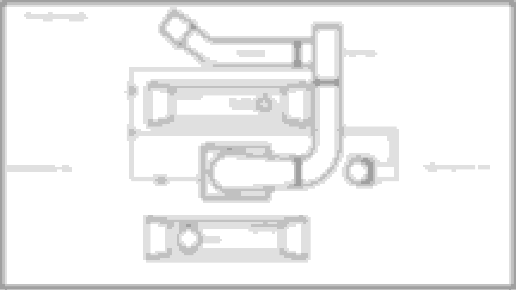
I've swapped out the SC pulley (4.25") for the 3.85". That was not as easy as you would think. They definitely don't want that thing coming off on its own. Secondly, I'm revisiting the PVC system. I'll be using a dual vacuum source (and I re-routed the catch can) of engine vacuum and super charger inlet vacuum. Using the SC alone did not generate enough vacuum at low loads to evacuate crank case gases properly. Once up and running, I'll post some more pictures.
Here is the new location of the catch can.
It's starting to get so packed on the driver's side, I have to get creative to mount things...
I added a lot of the new content to post #1. It updates some of the tuning notes, as well as the PCV changes including a PCV schematic that I'll post here:
I've swapped out the SC pulley (4.25") for the 3.85". That was not as easy as you would think. They definitely don't want that thing coming off on its own. Secondly, I revisiting the PVC system. I'll be using a dual vacuum source (and I re-routed the catch can) of engine vacuum and super charger inlet vacuum. Using the SC alone did not generate enough vacuum at low loads to evacuate crank case gases properly. Once up and running, I'll post some more pictures.
Here is the new location of the catch can.
It's starting to get so packed on the driver's side, I have to get creative to mount things...
I have some more driving and data logs. I want to throw out a question to others that have either a centrifugal SC or turbo C3. Does the blow through application generate the maximum manifold pressure (boost) under partial throttle positions or just wide open throttle? For example, would you expect full manifold boost at 50% throttle position? OR does the throttle plates drop enough pressure to not realize the full boost within the manifold? Anyone have experience or data on this? Remember, blow thru only, roots style are on the other side of the throttle plates. Thanks!
No sure what you are asking but I will give it a shot. Once that valve is closed you are under boost = zero vacuum. How much boost for simplicity of this is relative to TPS & RPM. The how much boost I don't think you are asking. WOT vs RPM will give you your "max" boost based on the VE of the motor. Other factors come into play here also....but at 50% throttle and our SC you are not under max boost, the SC isn't operating at its max speed and the VE of the motor is def not at 50% throttle....
No sure what you are asking but I will give it a shot. Once that valve is closed you are under boost = zero vacuum. How much boost for simplicity of this is relative to TPS & RPM. The how much boost I don't think you are asking. WOT vs RPM will give you your "max" boost based on the VE of the motor. Other factors come into play here also....but at 50% throttle and our SC you are not under max boost, the SC isn't operating at its max speed and the VE of the motor is def not at 50% throttle....
Let me try to clarify...
I understand all of what you described and the theory behind it, but thanks for the explanation. The question really is, what is the pressure drop across the throttle plates when the supercharger is spinning at a relatively high RPM (high engine RPM) but the throttle position or throttle plates are not at WOT? What manifold pressure have others seen with partial throttle compared to WOT manifold pressures?
Here is another way to ask the question: What is the manifold pressure with the engine at 5000 RPM and throttle at 50% vs the engine at 5000 RPM with the throttle at 100%? Therefore, the SC in both cases is spinning at the same RPM and in both cases, the full flow of the SC is trying to get into the manifold.
Does that clear up what I am looking for? NYCITI, you have a comparable build. What manifold pressure can you build at 5000 RPM at 50% throttle vs WOT at around 5000 RPM (engine)?
I have some more driving and data logs. I want to throw out a question to others that have either a centrifugal SC or turbo C3. Does the blow through application generate the maximum manifold pressure (boost) under partial throttle positions or just wide open throttle? For example, would you expect full manifold boost at 50% throttle position? OR does the throttle plates drop enough pressure to not realize the full boost within the manifold? Anyone have experience or data on this? Remember, blow thru only, roots style are on the other side of the throttle plates. Thanks!
KT
My logs show the same thing although mine is turbocharged and fuel injected. I make around 10lbs of boost at 41% throttle plate opening.
If you think about it, throttle plates were designed for naturally aspirated (N/A) operation where any restriction would reduce power. In a forced induction system, the air is compressed and does not require as big a pathway to get the same or more volume through. So a partially closed throttle can let more air through in forced induction than a fully open throttle in N/A.
10-4 DblTrbl
If you make 10 psi at 41% what do you make at WOT?


 11-14-2020, 08:10 PM


 I'm will adjust pulleys for more boost next spring but I wanted to get the car dialed in tune wise.