
Where does it go? (Steering Column)
 06-13-2016, 09:13 PM
#1
Melting Slicks

Thread Starter
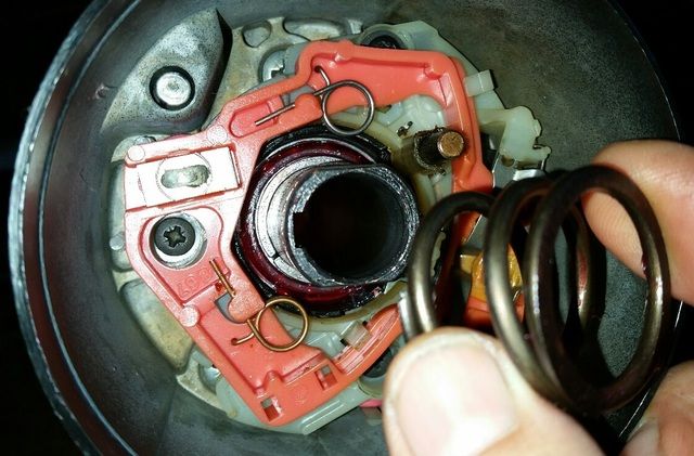
This retainer I'm holding fell out on disassembly (dammit).
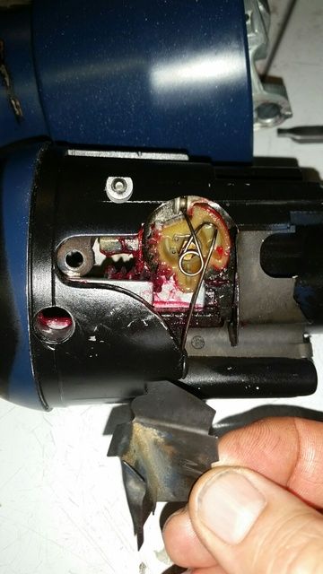
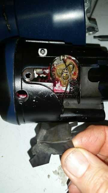
Going through the Shea documents/illustrations, I've yet to figure it's fitment back in.
Can anyone here please describe it's placement for me?
Thanks so much,
Steve


Going through the Shea documents/illustrations, I've yet to figure it's fitment back in.
Can anyone here please describe it's placement for me?
Thanks so much,
Steve
 06-14-2016, 01:13 AM
#2
Racer


I can point you in the right direction. It is a GM tilt lever opening shield, part #7805608. Find the hole where the tilt lever goes in, and you will have an idea where it goes.
The following users liked this post:
Cavu2u (06-14-2016)


The following users liked this post:
Cavu2u (06-14-2016)

The following users liked this post:
Cavu2u (06-14-2016)
06-18-2016, 12:30 PM
#6
Melting Slicks
Thread Starter
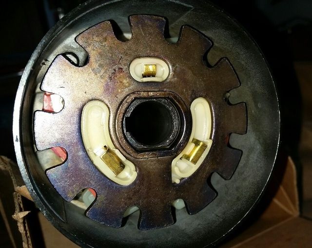
This top column assembly doesn't seem correct.
First Question: Should this Upper Shaft, with Wedge & Lock Rod installed, be free as shown here, at this stage?
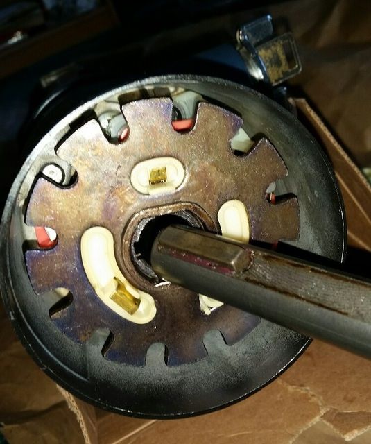
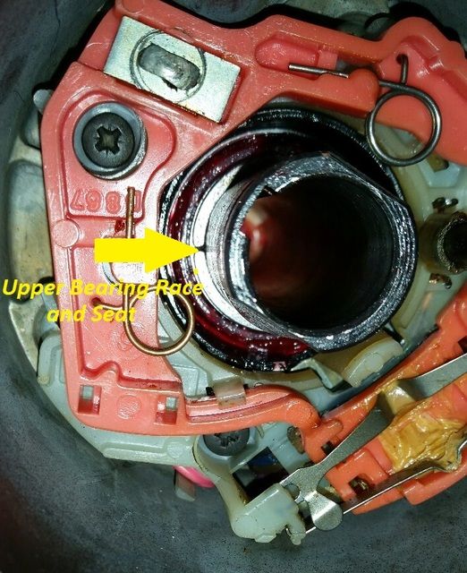
I'm sure I have the Upper Bearing Race & Upper Bearing Seat in place correctly.
My exploded diagram shows the Preload Spring going on next.
Preload Spring in place.
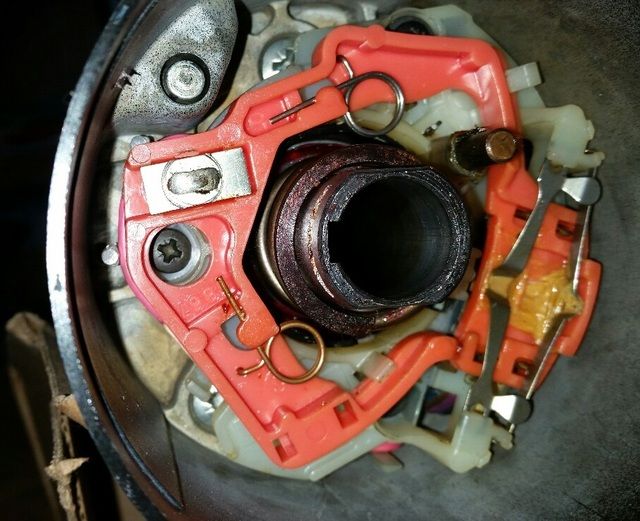
The Lock Plate & Horn Contact Carrier can only go together one way.
Next Question: Does the Preload Spring really ride on the thin surface of the Horn Contact Carrier?
Just seems different that when I disassembled it in the car.
Any thoughts on this assembly would be most welcome, as no one in town (yup, San Diego, California) wants to work on it.
Thanks in advance,
Steve
First Question: Should this Upper Shaft, with Wedge & Lock Rod installed, be free as shown here, at this stage?

I'm sure I have the Upper Bearing Race & Upper Bearing Seat in place correctly.

My exploded diagram shows the Preload Spring going on next.

Preload Spring in place.

The Lock Plate & Horn Contact Carrier can only go together one way.

Next Question: Does the Preload Spring really ride on the thin surface of the Horn Contact Carrier?

Just seems different that when I disassembled it in the car.

Any thoughts on this assembly would be most welcome, as no one in town (yup, San Diego, California) wants to work on it.
Thanks in advance,
Steve
06-18-2016, 01:46 PM
#7
Le Mans Master


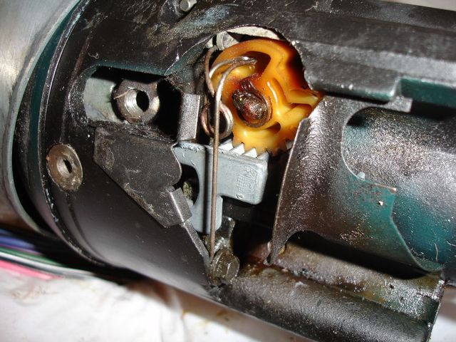
Its been a few years since I had one apart. but I think the spring actually sits inside the cancelling cam barrel of the contactor.
Everything else looks correct.
Try dropping Jim Shea a email
Everything else looks correct.
Try dropping Jim Shea a email
The following users liked this post:
Cavu2u (06-18-2016)
06-18-2016, 02:12 PM
#8
Melting Slicks
Thread Starter
I would think it rides inside or outside of it as well. I'm sure I have the correct Spring.

And someone else suggested I send JS a PM for assistance, which I did. It was around 2 months ago. I never heard back from him.
Appreciate the feedback.

Steve
Last edited by Cavu2u; 06-18-2016 at 02:13 PM.
06-18-2016, 02:23 PM
#9
Le Mans Master
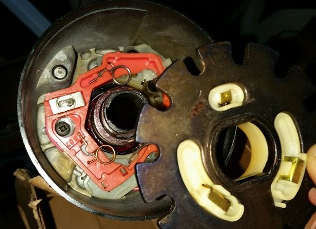
It (the spring) cant ride outside the barrel of the contact because those 2 "bumps" that are on there are what cancels the TS.
Take the spring and see if itll fit inside the barrel while its apart
Take the spring and see if itll fit inside the barrel while its apart
The following users liked this post:
Cavu2u (06-18-2016)
06-18-2016, 04:09 PM
#10
Melting Slicks
Thread Starter
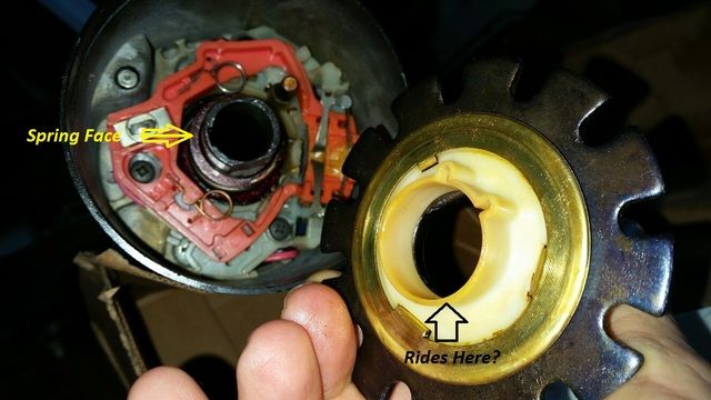
From every angle, from both Spring ends;


The Spring appears to ride on the thin nylon Horn Contact Carrier.

Just doesn't seem right.
Steve
06-18-2016, 09:18 PM
#11
Melting Slicks
Thread Starter

Well, that's the way it went together: Spring on thin nylon. Still a bit
 .
.Another thing I was apprehensive with, was the unrestricted travel of the Upper Shaft: it would slid right out with nothing obvious to hold it in, and the Steering Wheel is attached to it! It was only after the Lock Plate Retaining C-Clip was installed, that I realized the C-Clip also contacts the Wedge in that sliding Upper Shaft, preventing it and everything attached to it from completely coming out of the Upper Yoke.
Signal Cancelling works well. Shaft flats all aligned. Won't say I have it correct 'till I install and check it.

Steve
06-19-2016, 01:43 AM
#12
Instructor

I replace the signal lever switch on my 77 tilt tele and your reassembly looks correct. I looked back at the disassembly pictures I took. Did you ever see the papers Jim Shea wrote about steering column repair? lots of good tips and pics
The following users liked this post:
Cavu2u (06-19-2016)
 06-19-2016, 07:50 AM
#14
Melting Slicks
Thread Starter
I don't believe I would even had ever attempted to do such a thing if it wasn't for Shea's publications. Tips like aligning the Upper to Lower Shafts correctly due to very slight differences in one's machining would make-or-break proper Directional Signal Cancelling feature. I'm sure I'll reference them again as I go to install the column and attempt to get all switches and horn to work properly.
Thanks for the comment.
Steve
06-19-2016, 08:00 AM
#15
Melting Slicks
Thread Starter
C3,
That picture alone gave me the ability to carry on with the repair myself and voided the need to seek outside assistance with the assembly (if I could even FIND local assistance!).
You are so correct. This forum is fantastic.
Thank you all.
Steve

That picture alone gave me the ability to carry on with the repair myself and voided the need to seek outside assistance with the assembly (if I could even FIND local assistance!).
You are so correct. This forum is fantastic.
Thank you all.
Steve
06-19-2016, 06:12 PM
#16
Former Vendor
Member Since: Aug 2006
Location: Jeffersonville Indiana 812-288-7103
Posts: 76,656
Received 1,813 Likes
on
1,458 Posts
St. Jude Donor '08-'09-'10-'11-'12-'13-'14-'15

Steve-
Just back track your steps with this pdf... it takes you step by step how to assemble your column from where you are at now. And yes the center rod should move freely until you screw in the star bolt in the end, this is what pushes the rod and forces the column to lock.
Ernie
http://repairs.willcoxcorvette.com/1...-installation/
Last edited by Willcox Corvette; 06-19-2016 at 06:14 PM.
The following users liked this post:
Cavu2u (06-19-2016)
06-19-2016, 08:02 PM
#17
Melting Slicks
Thread Starter
Steve-
Just back track your steps with this pdf... it takes you step by step how to assemble your column from where you are at now. And yes the center rod should move freely until you screw in the star bolt in the end, this is what pushes the rod and forces the column to lock.
Ernie
http://repairs.willcoxcorvette.com/1...-installation/
Just back track your steps with this pdf... it takes you step by step how to assemble your column from where you are at now. And yes the center rod should move freely until you screw in the star bolt in the end, this is what pushes the rod and forces the column to lock.
Ernie
http://repairs.willcoxcorvette.com/1...-installation/

I've come across a bunch of small details that make a HUGE difference; In assembly it properly, or having to break it all back down to get that wrong orientated part correct.

For just a few examples:
Different Upper Shaft Flats orients/goes together with the Lower Shaft Rag Joint Flat in a particular way. Don't get it wrong.

On the '73 anyway, the C-Clip has a wide leg and a narrow leg. Can really go in only one way, but the shaft's final position to the Plate will let you know if you got some earlier assembly wrong.

Grooves have different lengths to accommodate eccentric C-Clip.

The Jim Shea documentation is extremely good at describing all these little gotchya's, and I couldn't have done this without it. And of course the help I received from you and those here on the forum.
Thanks so much.
Steve
06-19-2016, 08:20 PM
#18
Former Vendor
Member Since: Aug 2006
Location: Jeffersonville Indiana 812-288-7103
Posts: 76,656
Received 1,813 Likes
on
1,458 Posts
St. Jude Donor '08-'09-'10-'11-'12-'13-'14-'15
Jim is the bomb Steve.. lol.. I've got a video of the entire rebuild... but I've not had time to published it yet.. Sadly I should... but my time is cramped right now. It's an awesome vide but it needs to be edited and that takes twice the time to do as shooting the video.
We're going to do a 1978 column in four weeks and I plan to film it as well.
If you run into issues with this build just shoot me an email. I'm out of the office for the next three weeks but will monitor the support email address.
Ernie
We're going to do a 1978 column in four weeks and I plan to film it as well.
If you run into issues with this build just shoot me an email. I'm out of the office for the next three weeks but will monitor the support email address.
Ernie
The following users liked this post:
Cavu2u (06-19-2016)
06-20-2016, 01:21 PM
#19
Instructor
during the disassembly if you leave the bolt in in the shaft that you use with the lock release tool to disable the telescopic part of the column, the shaft won't come out.
The following users liked this post:
Cavu2u (06-20-2016)