
Supercharged 383 Engine Installation Progress
 08-03-2013, 05:14 PM
#1
Tech Contributor

Thread Starter
Member Since: Aug 1999
Location: At my Bar drinking and wrenching in Lafayette Colorado
Posts: 13,654
Received 4,924 Likes
on
1,930 Posts

An update on the 670-horse 383 VorTech supercharged engine installation:
I’ve been a little wrapped up with work assignments, so time available to work the final installation details has been a bit limited. But here is where we’re at now:
At the last posting, I had the engine/tranny/drivetrain all in the car and looking pretty good. Here is the engine compartment view of the drop-in:
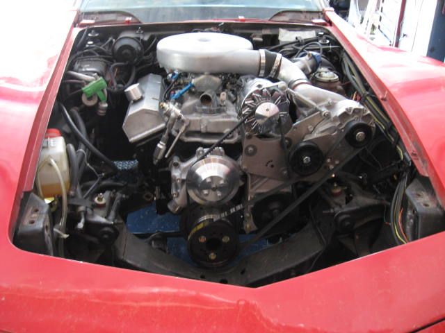
I spent a bit of time making sure it was all going to fit under the hood, so that will be the real test…
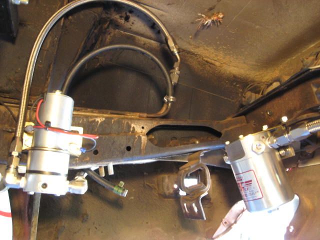
After the engine was bolted onto the engine mounts (accomplished in a few minutes as show in the previous post), I needed to spend a little time on the fuel delivery system: Dyno testing showed that the fuel suction side to the pump was critical, and that the pump needed a ˝” suction side system. The pump had to be adequate to produce 6 psi above the compressor pressure (boost running at 8.5 pounds required fuel pump pressure at about 15 pounds), so a good quality high pressure pump was mounted in the back of the chassis with a very good filter on the suction side to prevent any debris from entering the pump. Here is the pump and the filter, plumbed up with -8 AN lines on the suction side, in the back of the chassis. The factory hard-line down the frame rail was flared for -6 AN fittings on the pressure side of the system:
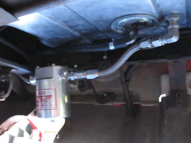
Tank installed, and the components have plenty of clearance:
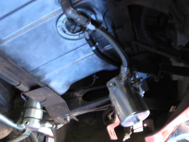
A new penetration had to be put in the tank to accommodate the custom fabricated ˝” stainless pickup system inside the tank:
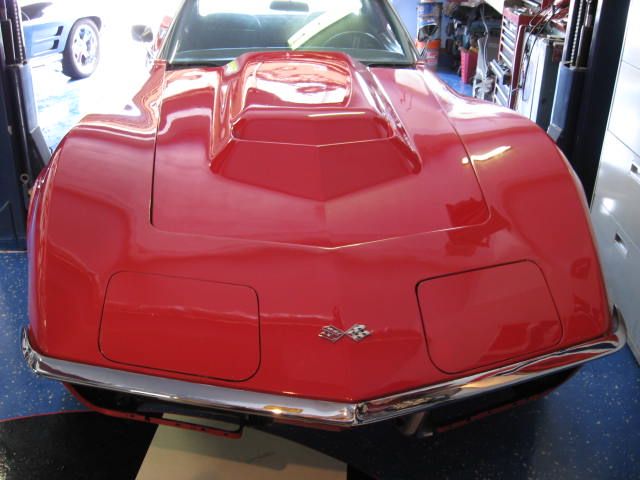
Final test fit of the hood shows that the entire engine/supercharger system fits under the hood. This hood is actually the stock small block hood that I cut and put the L88 raised center section into:
All that’s left is fuel pump electrical control system and water/cooling system hook-up. I’ll tinker a little with that this week…

Lars
I’ve been a little wrapped up with work assignments, so time available to work the final installation details has been a bit limited. But here is where we’re at now:
At the last posting, I had the engine/tranny/drivetrain all in the car and looking pretty good. Here is the engine compartment view of the drop-in:

I spent a bit of time making sure it was all going to fit under the hood, so that will be the real test…
After the engine was bolted onto the engine mounts (accomplished in a few minutes as show in the previous post), I needed to spend a little time on the fuel delivery system: Dyno testing showed that the fuel suction side to the pump was critical, and that the pump needed a ˝” suction side system. The pump had to be adequate to produce 6 psi above the compressor pressure (boost running at 8.5 pounds required fuel pump pressure at about 15 pounds), so a good quality high pressure pump was mounted in the back of the chassis with a very good filter on the suction side to prevent any debris from entering the pump. Here is the pump and the filter, plumbed up with -8 AN lines on the suction side, in the back of the chassis. The factory hard-line down the frame rail was flared for -6 AN fittings on the pressure side of the system:

Tank installed, and the components have plenty of clearance:

A new penetration had to be put in the tank to accommodate the custom fabricated ˝” stainless pickup system inside the tank:

Final test fit of the hood shows that the entire engine/supercharger system fits under the hood. This hood is actually the stock small block hood that I cut and put the L88 raised center section into:

All that’s left is fuel pump electrical control system and water/cooling system hook-up. I’ll tinker a little with that this week…
Lars

 08-03-2013, 07:46 PM
#3
Le Mans Master

Member Since: Oct 2002
Location: Las Vegas - Just stop perpetuating myths please.
Posts: 7,098
Received 373 Likes
on
356 Posts
Awesome progress. U make it look easy. Are u upgrading all lines up front to high press braided? I still see the old supply line. Is that going to be capped/plugged or do u have other uses? Nice location for the pump. BTW where's the regulator?
Mean look'n spiders above the fuel lines to the pump - be careful lars.
cardo0
Mean look'n spiders above the fuel lines to the pump - be careful lars.
cardo0


 08-03-2013, 09:22 PM
#6
Le Mans Master
i hate spiders. If I saw those in my car, i'd never drive it again
08-03-2013, 11:41 PM
#7
Tech Contributor
Thread Starter
Member Since: Aug 1999
Location: At my Bar drinking and wrenching in Lafayette Colorado
Posts: 13,654
Received 4,924 Likes
on
1,930 Posts
All the lines are either steel or braided stainless, except for non-pressurized return line splice sections, which are rubber fuel line. Dyno testing showed that 3/8" line can be used on the pressure side of the pump, but not on the suction side: All the suction side lines are 1/2", and the pressure side lines are 3/8". The stock 3/8" hard line is used down the frame, but it has been flared at both ends for AN fittings.
The old supply line coming out of the tank (rubber line) is inactivated. It has a plug in the end, and it's simply routed up alongside the tank to a point higher than the tank fuel level and secured. It can be hooked up again to the fuel line if the owner ever wants to do so for any reason, but it would take some restoration to make the old fuel system work again...
You can see the regulator in the first photo in this post: It's mounted right before the carb inlet lines. That photo was taken before the AN lines were hooked up. Here's a closer shot (the wires with the nasty splices were for the dyno testing only to run the electric fuel pump - I wouldn't install something like that in the engine compartment):

Those do look like spiders... that's funny... it's actually 'glass matting hanging from the rear deck where the owner plugged the luggage rack holes in the deck...
Last edited by lars; 08-03-2013 at 11:47 PM.
 08-04-2013, 11:03 AM
#10
Drifting

Everything looks great! Fits in there nicely. What cr ratio is the motor?
Honesty the only criticism I would make is that I do not like the bulkhead adapter for the pick up. The tank walls are think and that will and vibrate and leak, especially since it's so close to the pump. JMO.
I would have liked to see an o ring bung welded to the tank-those nylon washer s*ck. Even the stat o seals will leak if the fitting is vibrating a bit.
08-04-2013, 11:36 AM
#11
Tech Contributor
Thread Starter
Member Since: Aug 1999
Location: At my Bar drinking and wrenching in Lafayette Colorado
Posts: 13,654
Received 4,924 Likes
on
1,930 Posts
There will be no traction at all... The lack of traction will be the safety fuse for the half shafts...
I lowered the CR from 10.5:1 to 9.3. Running premium pump gas and a boost retard on the timing, there was no detonation at 8.5 pounds of boost. We even advanced the timing a bit to see if it would get into detonation, but we appear to have good margin.
The pickup is nowhere close to the pump, and does not see pump vibration since the pump is on the frame 2 feet away. I've done quite a few of these pickups, and I've never had one leak: The inside bulkhead nut is installed with a star washer to prevent rotation, and the entire connection is torqued to 60 ft/lbs... you have to put some effort into it to get the thing loose. We've been running these connections in our race cars for 10 years with no leaks or failures, and I have an identical system in my '64 street Vette that has been running leak-free for 3 years. If you don't get the fitting properly torqued, you'd probably have a problem... I even have a special tool made that will get inside the tank to hold the inside nut during torqueing.
Lars
Everything looks great! Fits in there nicely. What cr ratio is the motor?
Honesty the only criticism I would make is that I do not like the bulkhead adapter for the pick up. The tank walls are think and that will and vibrate and leak, especially since it's so close to the pump. JMO.
I would have liked to see an o ring bung welded to the tank-those nylon washer s*ck. Even the stat o seals will leak if the fitting is vibrating a bit.
Honesty the only criticism I would make is that I do not like the bulkhead adapter for the pick up. The tank walls are think and that will and vibrate and leak, especially since it's so close to the pump. JMO.
I would have liked to see an o ring bung welded to the tank-those nylon washer s*ck. Even the stat o seals will leak if the fitting is vibrating a bit.
The pickup is nowhere close to the pump, and does not see pump vibration since the pump is on the frame 2 feet away. I've done quite a few of these pickups, and I've never had one leak: The inside bulkhead nut is installed with a star washer to prevent rotation, and the entire connection is torqued to 60 ft/lbs... you have to put some effort into it to get the thing loose. We've been running these connections in our race cars for 10 years with no leaks or failures, and I have an identical system in my '64 street Vette that has been running leak-free for 3 years. If you don't get the fitting properly torqued, you'd probably have a problem... I even have a special tool made that will get inside the tank to hold the inside nut during torqueing.
Lars
08-04-2013, 12:58 PM
#12
Could you be kind enough to elaborate on the need to drop the CR down to the 9.3 level?
08-04-2013, 01:30 PM
#13
Safety Car

There will be no traction at all... The lack of traction will be the safety fuse for the half shafts...
I lowered the CR from 10.5:1 to 9.3. Running premium pump gas and a boost retard on the timing, there was no detonation at 8.5 pounds of boost. We even advanced the timing a bit to see if it would get into detonation, but we appear to have good margin.
The pickup is nowhere close to the pump, and does not see pump vibration since the pump is on the frame 2 feet away. I've done quite a few of these pickups, and I've never had one leak: The inside bulkhead nut is installed with a star washer to prevent rotation, and the entire connection is torqued to 60 ft/lbs... you have to put some effort into it to get the thing loose. We've been running these connections in our race cars for 10 years with no leaks or failures, and I have an identical system in my '64 street Vette that has been running leak-free for 3 years. If you don't get the fitting properly torqued, you'd probably have a problem... I even have a special tool made that will get inside the tank to hold the inside nut during torqueing.
Lars
Last edited by bluedawg; 08-04-2013 at 01:33 PM.
08-04-2013, 02:00 PM
#14
Tech Contributor
Thread Starter
Member Since: Aug 1999
Location: At my Bar drinking and wrenching in Lafayette Colorado
Posts: 13,654
Received 4,924 Likes
on
1,930 Posts
- Lower compression. Most supercharged engines run comp ratios between 8:1 to 9.5:1. Engines running higher boost levels will even lower comp down into the 7-range.
- Use an intercooler. As the air is compressed, it is heated from the energy put into the compression. A hot inlet charge will detonate more readily than a cooler charge. The cooler charge is also more dense, adding power while reducing detonation.
- Run water or water/alcohol injection. This cools the inlet charge while controlling burn rate to suppress detonation.
The distributor is an aftermarket HEI that I've put an aggressive mechanical curve in. It's also running vacuum advance to get the idle smoothed out and to assure cool running in city traffic. It's set up to produce 34 degrees total timing at 2500 rpm with 18 degrees initial. The vacuum advance pulls in an additional 14 degrees, making the engine idle at 32 degrees of timing. Under boost, the vacuum advance drops out, of course, and the ignition is controlled through a boost-controlled MSD system which retards the timing with each pound of boost (there is actually a vacuum hose hooked up to the MSD box, which senses manifold pressure). We did a lot of dyno pulls to optimize the boost retard, thinking that best power would be produced by not retarding the timing. Even though we did not get into any detonation by leaving the full 34-degree timing curve in it, we dialed in some retard to see what the numbers would do: Setting up the MSD for maximum boost retard surprised us by producing about 25 horsepower more with no other changes to boost or parameters.

Lars
Last edited by lars; 08-04-2013 at 02:05 PM.
08-04-2013, 02:17 PM
#15
Drifting
There will be no traction at all... The lack of traction will be the safety fuse for the half shafts...
I lowered the CR from 10.5:1 to 9.3. Running premium pump gas and a boost retard on the timing, there was no detonation at 8.5 pounds of boost. We even advanced the timing a bit to see if it would get into detonation, but we appear to have good margin.
The pickup is nowhere close to the pump, and does not see pump vibration since the pump is on the frame 2 feet away. I've done quite a few of these pickups, and I've never had one leak: The inside bulkhead nut is installed with a star washer to prevent rotation, and the entire connection is torqued to 60 ft/lbs... you have to put some effort into it to get the thing loose. We've been running these connections in our race cars for 10 years with no leaks or failures, and I have an identical system in my '64 street Vette that has been running leak-free for 3 years. If you don't get the fitting properly torqued, you'd probably have a problem... I even have a special tool made that will get inside the tank to hold the inside nut during torqueing.
Lars
I lowered the CR from 10.5:1 to 9.3. Running premium pump gas and a boost retard on the timing, there was no detonation at 8.5 pounds of boost. We even advanced the timing a bit to see if it would get into detonation, but we appear to have good margin.
The pickup is nowhere close to the pump, and does not see pump vibration since the pump is on the frame 2 feet away. I've done quite a few of these pickups, and I've never had one leak: The inside bulkhead nut is installed with a star washer to prevent rotation, and the entire connection is torqued to 60 ft/lbs... you have to put some effort into it to get the thing loose. We've been running these connections in our race cars for 10 years with no leaks or failures, and I have an identical system in my '64 street Vette that has been running leak-free for 3 years. If you don't get the fitting properly torqued, you'd probably have a problem... I even have a special tool made that will get inside the tank to hold the inside nut during torqueing.
Lars
 08-05-2013, 06:40 AM
#17
Safety Car

I love this build ! I am getting part by part everything I need to do this mod over the winter. I just got my pistons , and rods. ( I have a forged crank in motor now ) ..
Lars you got this looking great ! It is exactly what sbc guys needed to see to keep the old iron alive and kicking !!
Lars you got this looking great ! It is exactly what sbc guys needed to see to keep the old iron alive and kicking !!
08-05-2013, 08:29 AM
#18
Burning Brakes


Nice work. I am installing a vortech in my C3 as well and was wondering how I was going to fit it. Did this come as a kit with the mounting plate or did you source the plate individually?
08-06-2013, 02:52 PM
#19
Tech Contributor
Thread Starter
Member Since: Aug 1999
Location: At my Bar drinking and wrenching in Lafayette Colorado
Posts: 13,654
Received 4,924 Likes
on
1,930 Posts
The parts in the kit were used as a "suggestion." The main bracket casting was used without alteration, but custom shims & spacers were machined to align things properly. The "kit" has no provision for mounting the C3 style alternator, so all the alternator mounting brackets and tension system was fabricated from scratch. The main front mounting plate located the compressor too high to fit under the C3 hood, so this plate was re-machined and altered to lower the as-mounted height profile. This changed the angular relationship between the compressor outlet and the carb bonnet inlet, so the transition duct had to be cut, altered, and welded. The blowoff valve was not in the "kit," so it was procured and mounted on a custom welded and machined standoff. Very few parts were used "as-supplied," and pretty much everything had to be altered and re-made to get it to fit in the "envelope" of the C3.
Lars
Lars
08-11-2013, 11:54 AM
#20
Tech Contributor
Thread Starter
Member Since: Aug 1999
Location: At my Bar drinking and wrenching in Lafayette Colorado
Posts: 13,654
Received 4,924 Likes
on
1,930 Posts
Design and fabrication of the electrical control system for the car is almost complete. The blow-through application required use of a high volume, high pressure electric fuel pump, along with a boost-sensing MSD ignition system to allow automatic timing retard under boost. Both of these systems require adequate power sources from both battery and ignition-activated power sources, and the existing wires in the engine compartment were deemed inadequate.
So the fabrication starts…
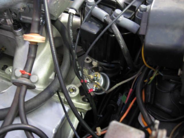
For the fuel pump, I wanted an oil pressure cutoff switch that would shut the pump off in the event of engine failure or a catastrophic accident. But I did not want the full amperage to the pump running through the switch. So a fuel pump relay system has been designed so that only the relay activation current is run through the oil pressure switch. Here is the oil pressure switch installed and rough-wired at the back of the engine:
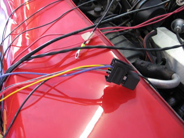
The oil pressure switch allows the relay to be activated (and the fuel pump to run) when the starter is engaged and/or when oil pressure is over 5 psi, so it gets power both from the starter “R” terminal and from the ignition switch through its NO and NC terminals. Here is the fuel pump relay ready to be mounted up and terminated to the harness:
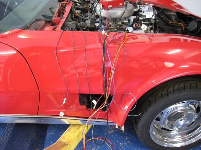
The entire harness is now hanging over the fender, waiting for a new fuseblock and power distribution system from Painless Wiring – this will allow me to mount the MSD, fuel pump relay, and the new power center to a fabricated panel that will mount to the passenger side inner wheel well, thus avoiding hacking into any existing (and inadequate) wires in the engine compartment:
Panel will be fabricated tomorrow, and the new parts from Painless should be here at the same time, allowing final mounting, hookups, and wrapping of the new electrical control system harness… photo of the completed system to come…
Lars
So the fabrication starts…
For the fuel pump, I wanted an oil pressure cutoff switch that would shut the pump off in the event of engine failure or a catastrophic accident. But I did not want the full amperage to the pump running through the switch. So a fuel pump relay system has been designed so that only the relay activation current is run through the oil pressure switch. Here is the oil pressure switch installed and rough-wired at the back of the engine:

The oil pressure switch allows the relay to be activated (and the fuel pump to run) when the starter is engaged and/or when oil pressure is over 5 psi, so it gets power both from the starter “R” terminal and from the ignition switch through its NO and NC terminals. Here is the fuel pump relay ready to be mounted up and terminated to the harness:

The entire harness is now hanging over the fender, waiting for a new fuseblock and power distribution system from Painless Wiring – this will allow me to mount the MSD, fuel pump relay, and the new power center to a fabricated panel that will mount to the passenger side inner wheel well, thus avoiding hacking into any existing (and inadequate) wires in the engine compartment:

Panel will be fabricated tomorrow, and the new parts from Painless should be here at the same time, allowing final mounting, hookups, and wrapping of the new electrical control system harness… photo of the completed system to come…
Lars