
Power Lock Wiring
 10-22-2007, 12:39 AM
#1
Instructor

Thread Starter

Member Since: Jul 2005
Posts: 124
Likes: 0
Received 0 Likes
on
0 Posts

Hi
I have a bit of a problem with my power locks on my '78 vette. I've been debugging them this weekend but can't get them working 100%.
Problem is, on the passenger side (PS), when I hit the lock switch, not enough power gets sent to the actuators to move the locks as they should. My voltmeter reads only about 8 volts reaching the actuators when the PS switch is used, compared to about 12 volts when the Driver's side switch is used.
So, here's what I debugged:
From the PS switch, around 12 volts leave out of the pink and purple wires when I hit the PS switch. So far so good, and the switch is thus not the problem.
But, only about 8 of these 12 volts reach the pink and purple wires on the Driver Side. The remaining 4 volts are getting lost somewhere within the dash.
Using my acrobatic skills, I got under the dash on the driver's side. I could see the pink and purple wires coming in from the driver's door. But, I was surprised to see that they do not go directly to the pink/purple wires on the passenger side. Rather, they connect to two sets of wires that come out from under the dash. One set has a white wire and a green wire coiled around each other. The other set has a brown wire and a blue wire. The purple wire went to one of these sets, while the pink went to the other.
Has anyone noticed this? Why do the pink/purple wires on the Driver's side not go directly to the pink/purple wires on the passenger side? What are these two sets of wires for? (the white wire and green wire set, and the brown wire and blue wire set). Any tips on debugging where the voltage is getting lost?
Thanks
PJ
Last edited by pj_corvette; 10-22-2007 at 12:42 AM. Reason: simplify description
 10-22-2007, 03:51 AM
#2
Safety Car


Hi
I have a bit of a problem with my power locks on my '78 vette. I've been debugging them this weekend but can't get them working 100%.
Problem is, on the passenger side (PS), when I hit the lock switch, not enough power gets sent to the actuators to move the locks as they should. My voltmeter reads only about 8 volts reaching the actuators when the PS switch is used, compared to about 12 volts when the Driver's side switch is used.
Go to the back of the switch if you haven't done this and do your test. I used some emory paper and it cleaned a varnish like substance off the contacts.
From the PS switch, around 12 volts leave out of the pink and purple wires when I hit the PS switch. So far so good, and the switch is thus not the problem.
I still have to do the passenger's side...this may be a good time to get into and we can work through this together if you don't get solved this weekend.


 10-22-2007, 10:56 AM
#6
Racer
Member Since: Mar 2006
Location: Rochester New York
Posts: 326
Likes: 0
Received 0 Likes
on
0 Posts
Maybe this will help, maybe not (different years)
My '81 has electric locks AND cylinders (when you insert the key to unlock the door, it automatically unlocks both sides YAY). Marvelous as it sounds, it was in pieces when I got it, and after many bloodied knuckles, I was only able to get one side working and have been unable to figure where my shorts were (I had a date that ended like that once ).
).
Did your year have this option, and if so could it be the culprit somehow? The lock cylinders have tiny contacts on them that could be corroded/broken, possibly.
My '81 has electric locks AND cylinders (when you insert the key to unlock the door, it automatically unlocks both sides YAY). Marvelous as it sounds, it was in pieces when I got it, and after many bloodied knuckles, I was only able to get one side working and have been unable to figure where my shorts were (I had a date that ended like that once
).Did your year have this option, and if so could it be the culprit somehow? The lock cylinders have tiny contacts on them that could be corroded/broken, possibly.
10-22-2007, 06:09 PM
#7
Instructor
Thread Starter
Member Since: Jul 2005
Posts: 124
Likes: 0
Received 0 Likes
on
0 Posts
Hmm. I'm not sure if the car has electric lock cylinders as you describe. But that got me thinking, it does have a factory alarm system. I'm wondering if the white/green and brown/blue wire sets have somehting to do with the alarm system being hooked up to the doors.
Does anyone have the schematics for the alarm system? I'm not home, so I dont know if the electrical troubleshooting manual has that schematic.
Thanks
PJ
Does anyone have the schematics for the alarm system? I'm not home, so I dont know if the electrical troubleshooting manual has that schematic.
Thanks
PJ
Last edited by pj_corvette; 10-22-2007 at 06:14 PM.
10-23-2007, 12:37 AM
#8
Instructor
Thread Starter
Member Since: Jul 2005
Posts: 124
Likes: 0
Received 0 Likes
on
0 Posts
I think I found what's wrong
The previous owners installed an alarm system, which currently does not work.
Those white/green wires and blue/brown wires come from the alarm box, which was hidden behind the dash.
The pink and purple wires coming from the door lock are probably connected to this alarm system, and somewhere in that spaghetti bowl probably lies the problem.
Thanks for your help anyway guys.
11-14-2011, 10:52 AM
#10
1st Gear

Member Since: Nov 2011
Posts: 1
Likes: 0
Received 0 Likes
on
0 Posts
Hi Ladies and Gentlemen,
best regards from Germany, I am a brandnew member of your forum.
I found it because I have questions about some features of my newly bought Corvette. I have a model from 1981 that looks pretty good and is inside and out in good shape.
I read this thread about the power door locks interestedly and have a question about this:
The User "mxscooter" wrote that he has "electric locks and cylinders" in his car. How can I find out if my car has electric cylinders too?
The switches in both doors that lock and unlock the doors from inside the car both work properly. But opening/locking the door with a key from either side only unlocks/locks this door mechanically.
Can you give me support how I can find out if I have an electrical problem or if my car hasn't got this option with electric cylinders?
Was it possible in 1981 to order this option extra? According to the list of available options I only found the feature "power door locks".
Very many thanks in advance for your replies.
With best regards from cold autumn-time in germany,
Lupocamino
11-14-2011, 02:44 PM
#11
Instructor
The "electric Lock" feature that is described above is an aftermarket add on. The only option was for the conventional electric locks (the door key did not open the other side)
As for debugging the door locks -- remember that the system will only work if BOTH of the switches is fully functional. If either switch has failed or partially failed, the entire system will act strange. My suggestion, check the ground in the drivers side door and if it is good, replace both switches -- you can buy aftermarket switches without the word "lock" on them for about $10. After you you prove the fix you can invest in the additional price of the the"lock" switches if you are so inclined. It will save you hours of aggravating troubleshooting with a fairly complex (however elegant) wiring implementation
As for debugging the door locks -- remember that the system will only work if BOTH of the switches is fully functional. If either switch has failed or partially failed, the entire system will act strange. My suggestion, check the ground in the drivers side door and if it is good, replace both switches -- you can buy aftermarket switches without the word "lock" on them for about $10. After you you prove the fix you can invest in the additional price of the the"lock" switches if you are so inclined. It will save you hours of aggravating troubleshooting with a fairly complex (however elegant) wiring implementation
08-17-2012, 09:20 AM
#12
Instructor

This is an old post but has a lot of great information. My problem is on my 80 I replaced both door lock wiring harnesses and bought new switches. I wired the harness to the same color wires in the car but when I plug in the new switches the fuse blows. Blamed it on bad switch and sent them back for exchange. Now have new switches but have read that on the new harness same color wires dont necessarily go together. Anyone else have this problem or more inportantly anyone have a solution.
09-21-2012, 11:00 PM
#13
Racer
mine is doing the same thing although i have a 81, i started a new thread but i am still stuck, it seems every wiring diagram i can find looks simple but its not working for mine, sent the first set of replacement swithches back today, got a nother set from a local parts store, going to try tomorow but i am still stuck
09-21-2012, 11:10 PM
#14
Le Mans Master


Member Since: Jan 2006
Location: Boca Raton Florida
Posts: 9,192
Likes: 0
Received 24 Likes
on
23 Posts
Probably not the switches. The pigtail connector for the left is different than the right, same wire colors, different pins. If you match the pigtail wires to the same color harness wires and the pigtails are the same it will blow fuses.
09-22-2012, 07:58 AM
#15
Instructor
So how did you figure out the "right" way. I suppose its orange to orange both sides is it the plack wire thats wrong or one of the others. I think blur grey and tan. I knew someone on here would have a solution
09-22-2012, 08:29 AM
#16
Le Mans Master
Member Since: Jan 2006
Location: Boca Raton Florida
Posts: 9,192
Likes: 0
Received 24 Likes
on
23 Posts
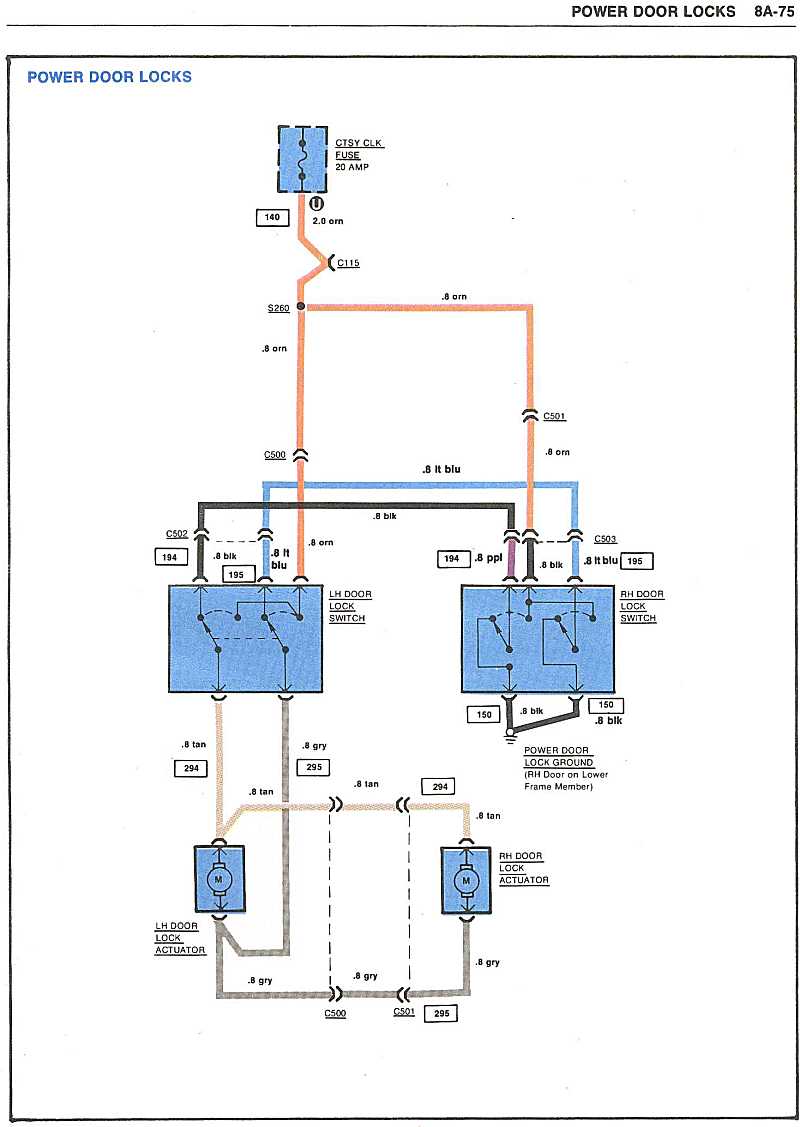
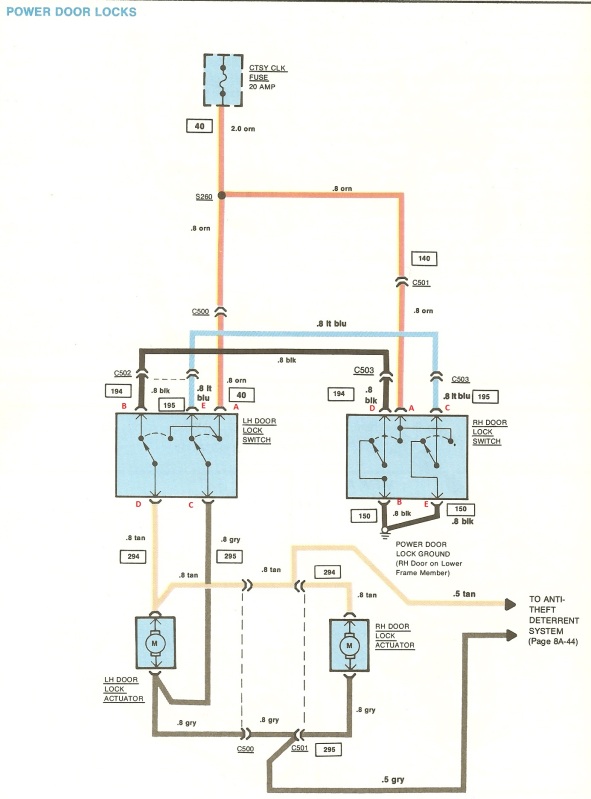
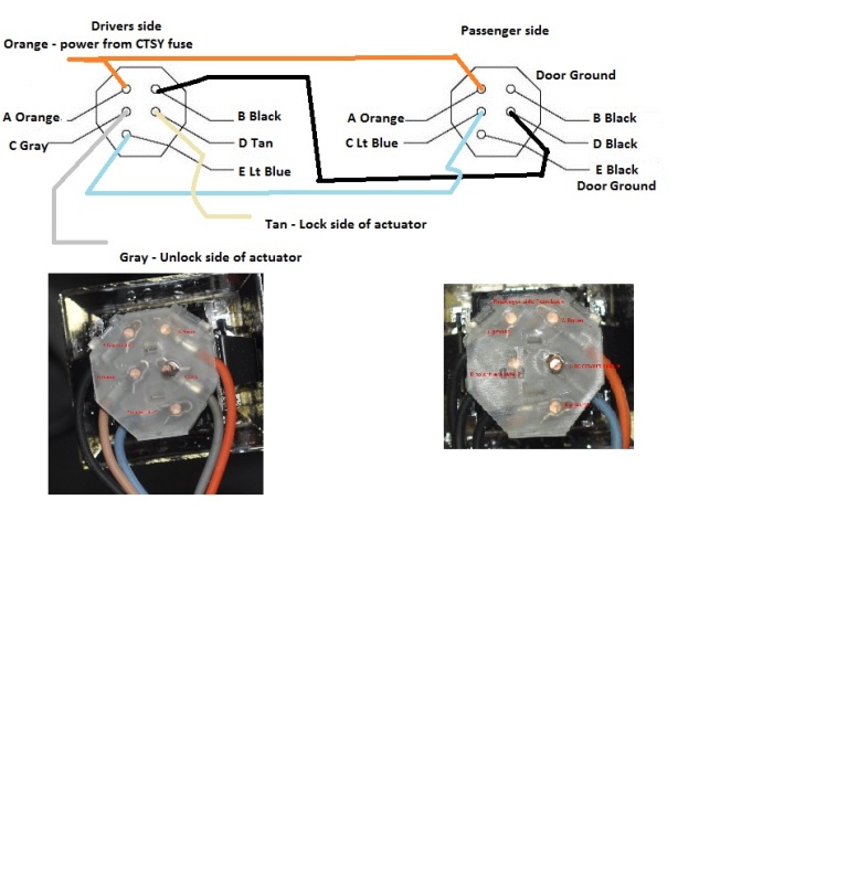
OK, look at your pigtails. They have a letter stamped into the plastic. The letters on the diagram are in red right at the connection point on the switch. Match the colors on your wire harness (not the pigtail) to the letter on the plastic connector
The orange wire is power and it goes to A on both switches
Blue goes from E on the drivers side to C on the passenger
Black from B drivers side to D passenger
Passenger side there are 2 more black to ground for B and E
Drivers side D is the Tan wire for Unlock
Drivers side C is gray for lock.
The orange wire is power and it goes to A on both switches
Blue goes from E on the drivers side to C on the passenger
Black from B drivers side to D passenger
Passenger side there are 2 more black to ground for B and E
Drivers side D is the Tan wire for Unlock
Drivers side C is gray for lock.
 09-22-2012, 04:31 PM
#18
Racer
Six, that is a awsome diagram and pics, that is just what i need, whats the red writting on the actuall pictures? too small to read even when i blew it up, but see the way you have is alot different from the wiring diagram we all have. it just started to down pour here i will check it out in a few
09-22-2012, 05:13 PM
#20
Racer
the Delco gods have shined, your pictures are a life saver, drivers side was right for me, the pass side i had to play with the 3 black wires, i know the 2 from the door should go to the 2 pins on the bottom, but for some reason i had to put 1 on the bottem then the other door ground up to where the black crosses over to the drivers door, but low and behold, both sides work great and no blown fuses, just gat to put the wires back in the plugs and button everything up