
The Mother of all LED testing
 01-31-2014, 12:26 AM
#1
Burning Brakes

Thread Starter

Ok, that's a huge overstatement but my High School English teach once taught me when I start a speech to capture everyone's attention and you can't see a Playboy picture from the text on the main page. 
While this ongoing thread isn't probably THE ultimate LED light testing thread, I hope some people will enjoy it. It's -1F right now so not much going on in the garage and I was getting bored and looking for something to do. So I came up with this idea. If you've seen the Altanta Speedometer kit version on this forum or YouTube, that's kind of what I'm working on. I didn't really care for the way the AS kit worked for the center gauges so I'll try to improve upon that.
My main goal was to see if LED lighting is all of that and bag of chips. So how to go about it? Well, I need some gauges. Hmm, mine are all in my car with new faces, etc, plus it's all together and don't want to mess with it just for testing.
So I looked around and found a place just 15 minutes away that parts out vettes on occasion *and* they had a full dash gauge set. So I ran down and picked it up for $200. It's from a '75 I believe so it's got the white face gauges, but I have my old gauges and face plates to test with as I have the green paint on mine.
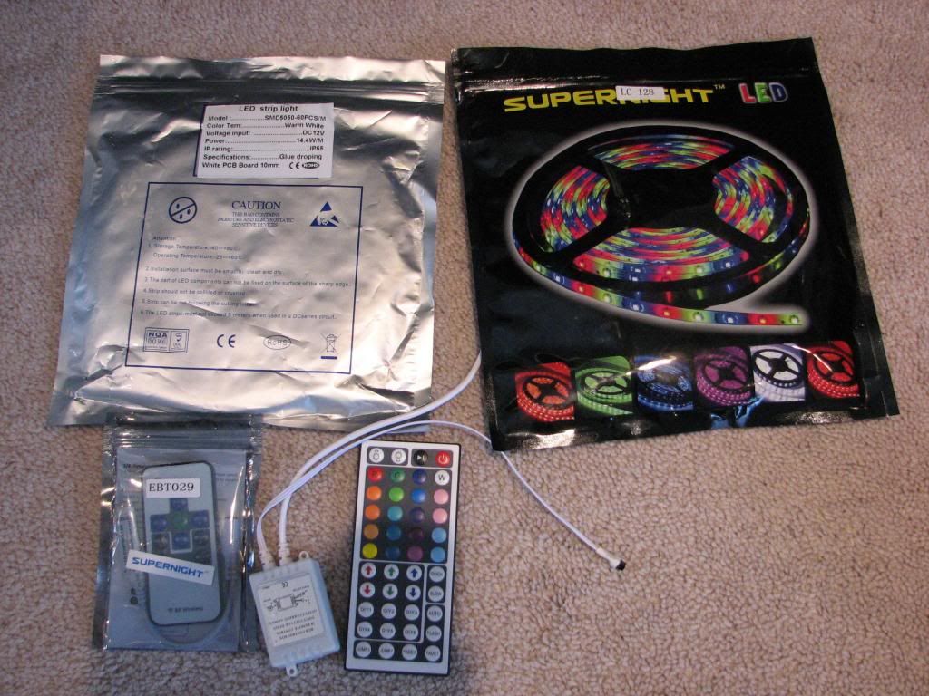
Off to eBay I went to order some LEDs. I've got some strips in both warm white, and colors as well as some LED 1895 (gauges) and 194 (side marker) bulbs. I also needed a 12v supply so I bought a Korad variable power supply which I got for $100 on eBay.
My camera is a bit old as I keep holding off upgrading, so it's a lowly Canon S3 IS that has a delay exposure feature to take good night shots as well as a good tripod (essential). It will have to be good enough.
I've got a couple more things to get together before I start but wanted to get the thread going for some input.
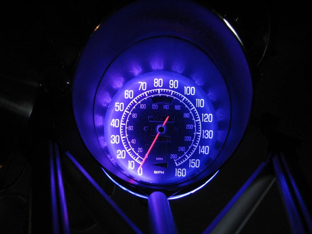
From playing around a bit today, I'll tell you, the multi-color LEDs are looking like a really cool option.
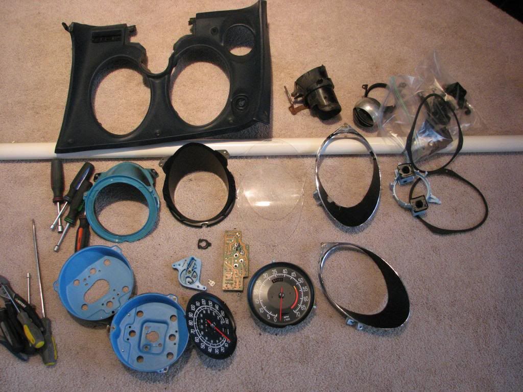
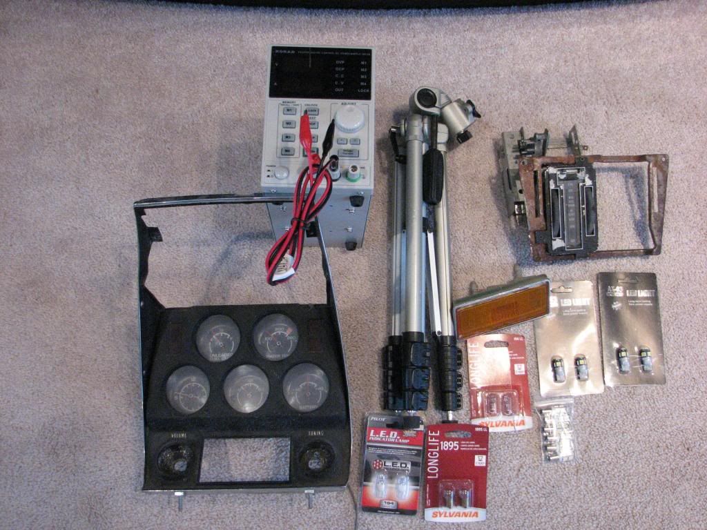
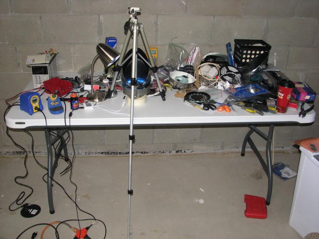
Some pictures of my booty that I'm cleaning up and getting ready:
12v power supply, camera stand, side marker, bulbs:
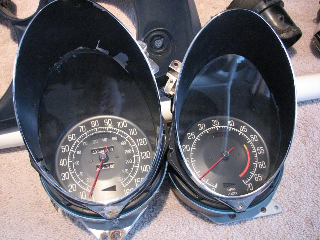
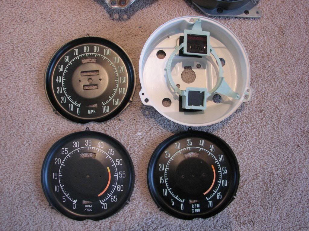
My 2 green faces leftover from putting new ones in, plus an extra 75 (white) I had laying around after I did my mechanical to electric tach conversion. I also had the can leftover from the conversion as well that will be white instead of the standard green or blue that the early and later years had. The idea was that the matte white would shine brighter.
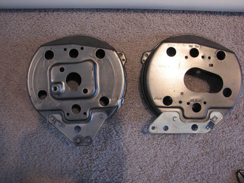
stock bulb holes (5/8"):
While this ongoing thread isn't probably THE ultimate LED light testing thread, I hope some people will enjoy it. It's -1F right now so not much going on in the garage and I was getting bored and looking for something to do. So I came up with this idea. If you've seen the Altanta Speedometer kit version on this forum or YouTube, that's kind of what I'm working on. I didn't really care for the way the AS kit worked for the center gauges so I'll try to improve upon that.
My main goal was to see if LED lighting is all of that and bag of chips. So how to go about it? Well, I need some gauges. Hmm, mine are all in my car with new faces, etc, plus it's all together and don't want to mess with it just for testing.
So I looked around and found a place just 15 minutes away that parts out vettes on occasion *and* they had a full dash gauge set. So I ran down and picked it up for $200. It's from a '75 I believe so it's got the white face gauges, but I have my old gauges and face plates to test with as I have the green paint on mine.
Off to eBay I went to order some LEDs. I've got some strips in both warm white, and colors as well as some LED 1895 (gauges) and 194 (side marker) bulbs. I also needed a 12v supply so I bought a Korad variable power supply which I got for $100 on eBay.
My camera is a bit old as I keep holding off upgrading, so it's a lowly Canon S3 IS that has a delay exposure feature to take good night shots as well as a good tripod (essential). It will have to be good enough.
I've got a couple more things to get together before I start but wanted to get the thread going for some input.
From playing around a bit today, I'll tell you, the multi-color LEDs are looking like a really cool option.
Some pictures of my booty that I'm cleaning up and getting ready:
12v power supply, camera stand, side marker, bulbs:
My 2 green faces leftover from putting new ones in, plus an extra 75 (white) I had laying around after I did my mechanical to electric tach conversion. I also had the can leftover from the conversion as well that will be white instead of the standard green or blue that the early and later years had. The idea was that the matte white would shine brighter.
stock bulb holes (5/8"):
Last edited by StingrayLust; 01-31-2014 at 12:30 AM.


 02-09-2014, 04:00 AM
#5
Burning Brakes
Thread Starter
Ok, I haven't forgotten this thread, just getting my supplies and thoughts in order.
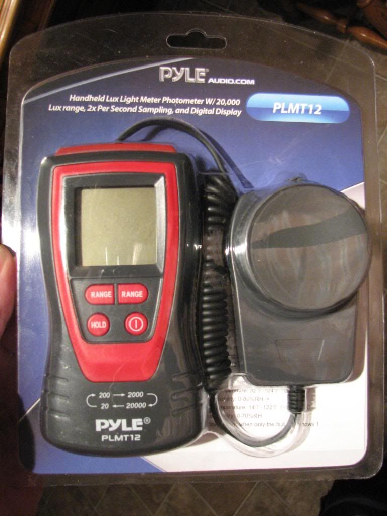
Since my Canon S3 IS is a bit low end for testing, I thought I'd try and be a bit more tech savvy and get me a LUX photometer. Seeing as I have no real use for a photometer outside of this testing, I was trying to be cheap and ordered a Pyle PLMT12 from Adorama for about $26 (+$3 shipping). Well it arrived last Friday and thought maybe I might be ready to start some limited testing. Well that came to a halt pretty fast when I took the meter out, put in a good 9V battery, and hit the On button. And nothing... dead, POS Chinese crap. So much for the nice "QC Passed" sticker on the back!!!
My idea is to tackle the 3 interior pieces:
#1 - speedo and tach
#2 - center cluster gauge
#3 - heater control
I'm still gathering up my ideas on what I want to do now that I have almost all of the materials that I want. To give you an idea of things that I'm working on I've taken some pictures of where I'm at. These aren't going to be my comparison pictures as I'll have to get my photometer working and a better setup, consider these just a teaser then.
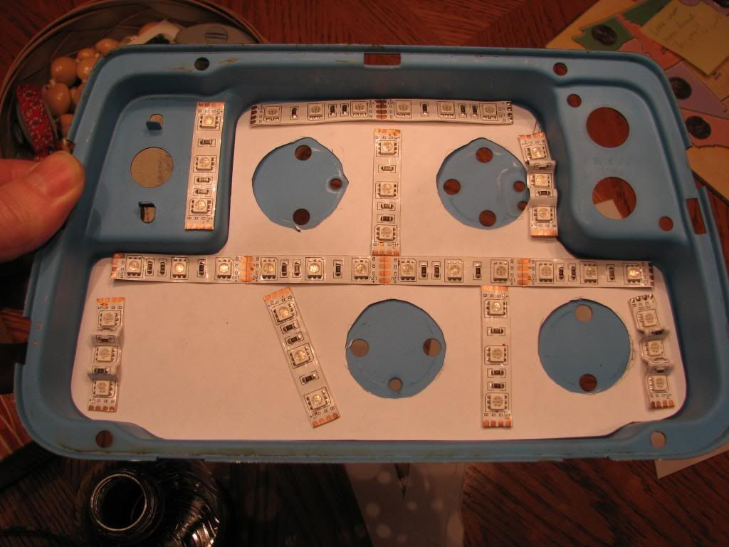
Here's some nice, "warm white" LED strips I got off of eBay. My idea is that they would fit in-between the gauge face and reflection off the plastic housing.
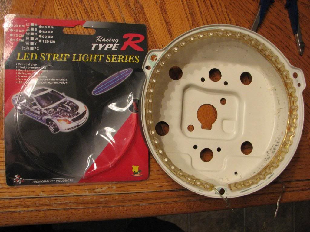
If I was going to just stay with single color LEDs, this might be my choice for using in the speedo and tach. While I don't have LUX numbers for the 4 incandescent vs 4 LED 5050 (1894bulb) vs these strip lights, I must say they're very bright and fit in there almost perfectly without any cutting.
However after playing around with stuff, I'm pretty set upon my goal of having RGB LEDs that I can switch colors around when I want. I can certainly see why lots of people choose the blue LEDs as they really make the colors pop and leave the black background very black.
So in my quest for introducing RGB LEDs into my cluster, I began with how I would attach the speed and tach. While it seems that Atlanta Speedometer has taken down all links to their LED dash kit, I remember seeing it and thinking that's pretty neat idea. So how to replicate it? If you've never seen the kit, look around to see if you can find some pictures.
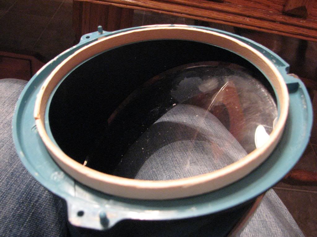
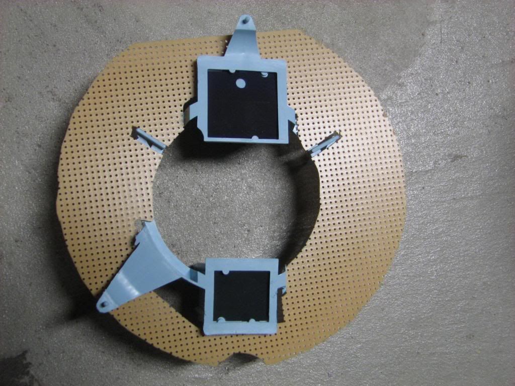
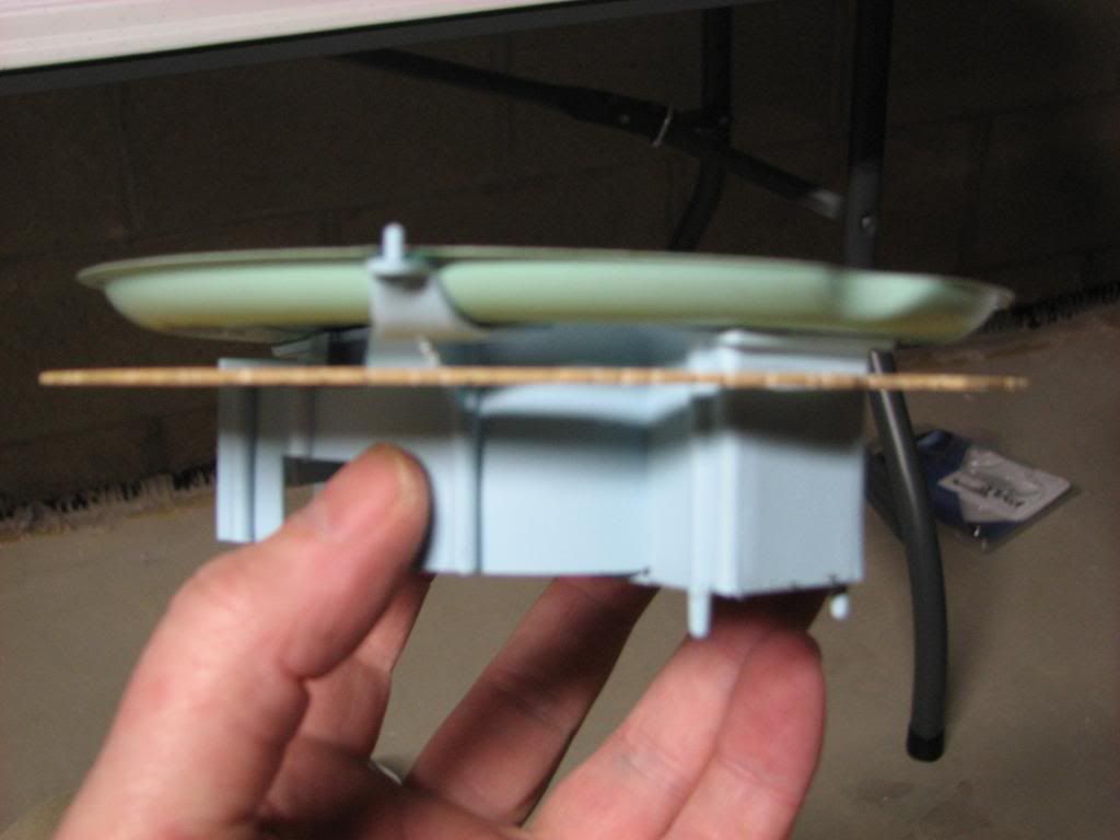
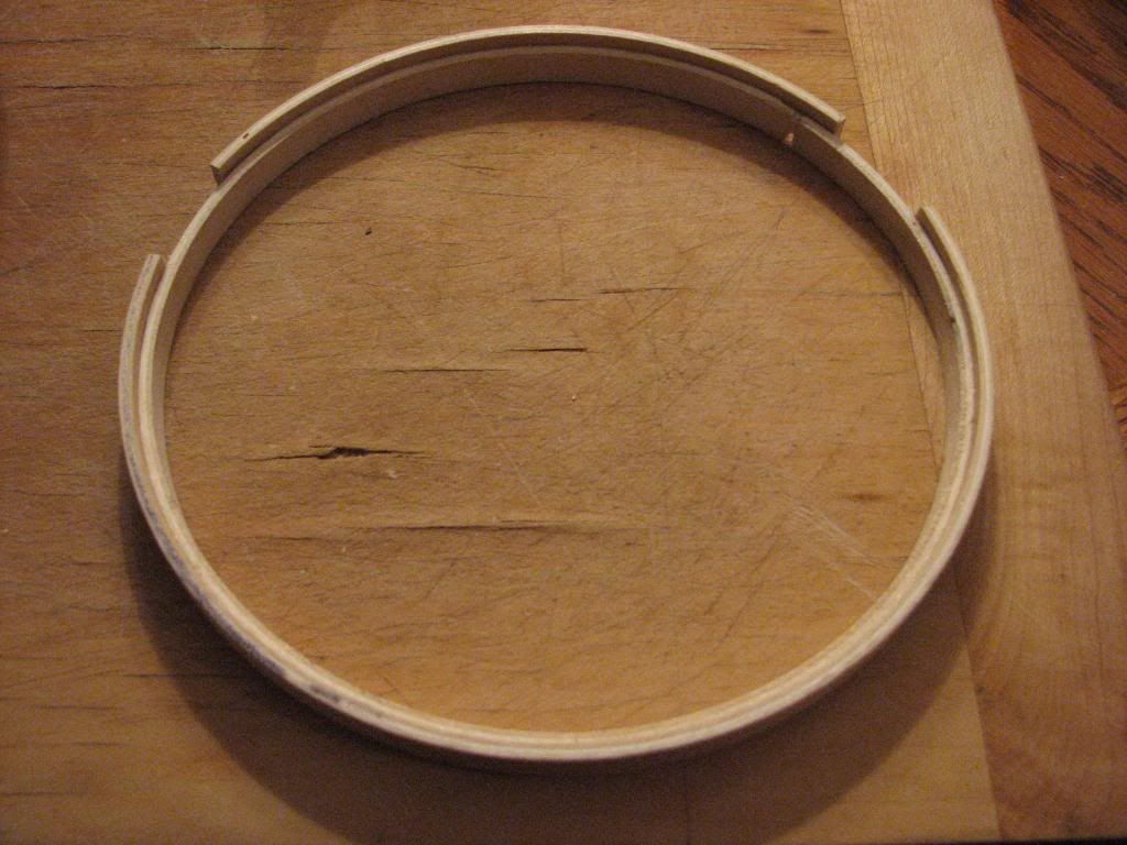
Since I needed to put some distance between the back can and the front plastic housing, I tried using some oven hardened clay that I formed. It didn't turn out that great and my pictures I just took were bad so I didn't even put them here. Next I tried some wood pieces I found at Michaels craft store that are probably used for needle point of some sort, 7" and 6" wood circles. I needed to cut them a bit and bend the inner one a bit with some boiling water. This is kind of what I was thinking of:
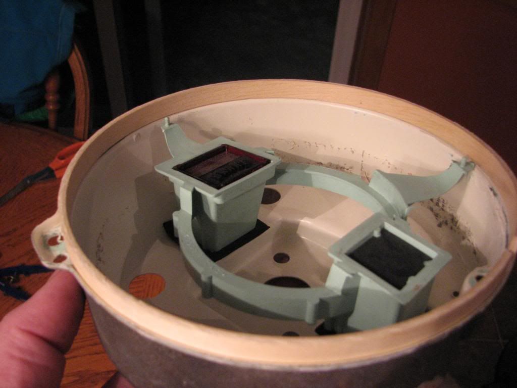
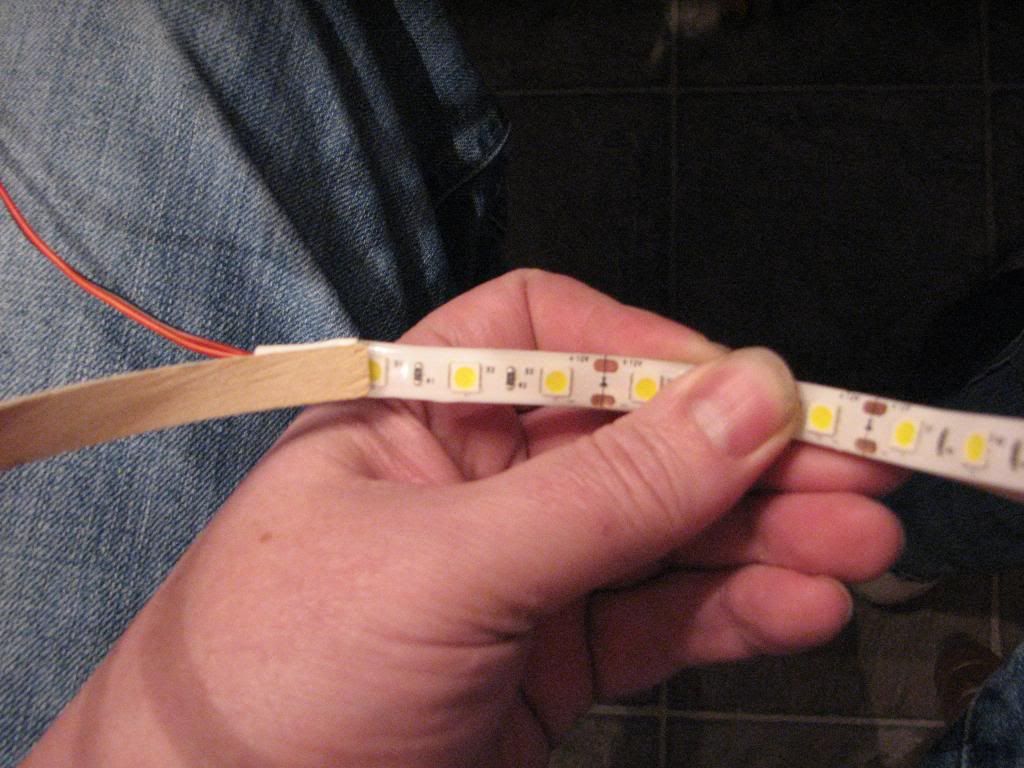
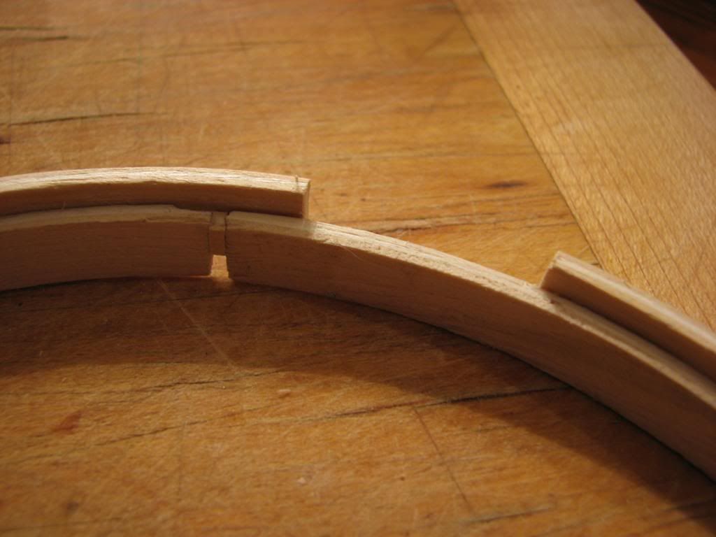
The wood strips are exactly the right width for my LED strips. My idea is to put the LED on the inside:
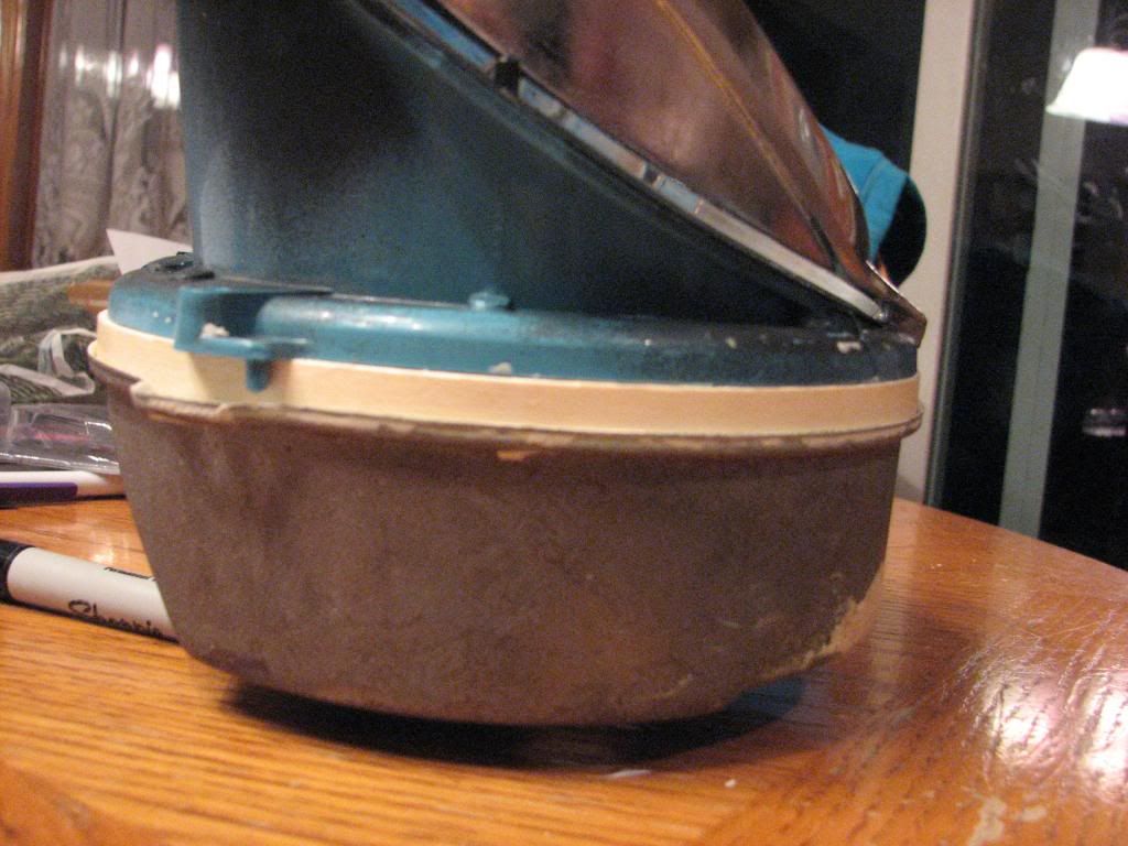
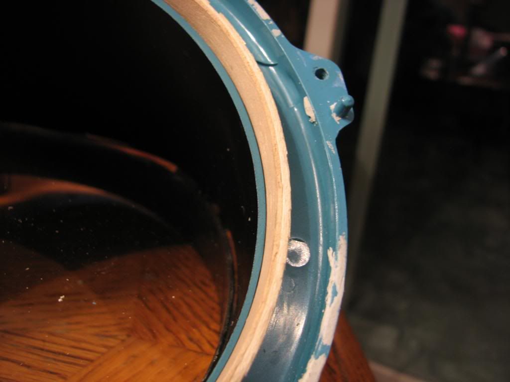
Trying to be a stickler for details, I found an issue. That issue is that the wood separator allows someone looking from the side to easily see my lights:
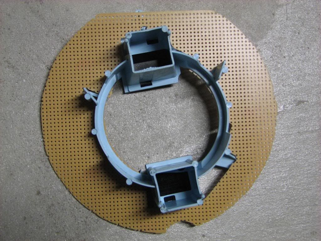
I think that would bother me after a while, knowing it's there. So I thought what about a diffuser on the inner circle of the plastic housing that would be painted black (or ultimately formed with black resin from a RTV mold) and would block the line-of-sight to the LEDs. So I worked on this:
That seems like it would work, but the materials for a RTV mold and the resin aren't cheap, and I'm not sure this is the ultimate direction I need to go.
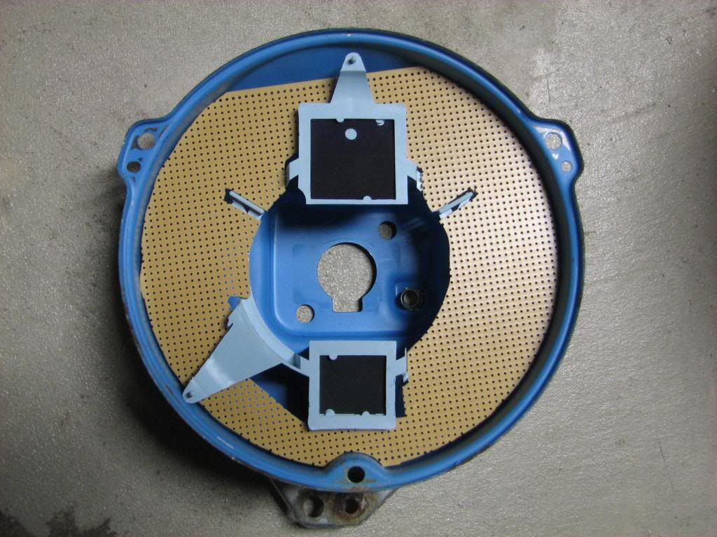
So I thought about alternatives. How else could I get LEDs close to the rim of the speed/tach face and have it bounce off the plastic housing? Sure I could just stick 4 of the 1894 bulbs in the correct holes, add some reflector material, and call it a day, but you lose the ability to change colors. So I started thinking about something else and came up with this:
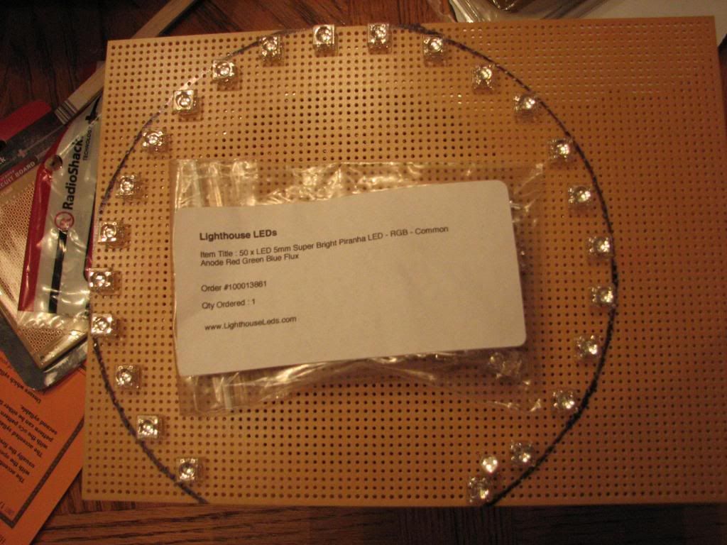
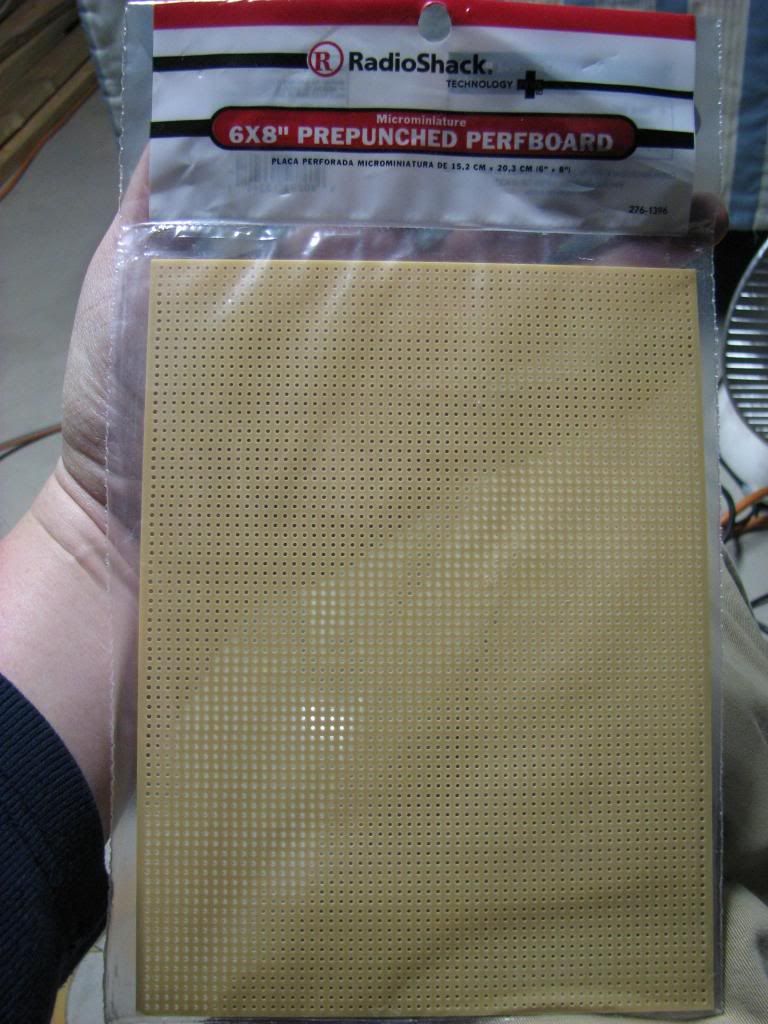
I bought some protoboard/perfboard from Radio Shack and had already ordered some Piranha superbright RGB LEDs from eBay. I also have a huge assortment of resistors on their way as well. I already have some nice radio frequency (RF), instead of infrared (IR), remotes for my LED strips in the opening set of pictures.
My idea would be to build my own ring that sits right behind the face plate and reflect off the plastic housing. The plastic housing would need some upgrades if I was to get maximum light reflection. So I've looked at getting some real titanium white paint and I've also actually bought some silver leaf that I could apply to the plastic. I'm not sure how that's all going to look yet as there's lots of work to be done before I get there.
I've also thought of things like how cool would it be to be able to dim my lights from my original switch which is something I often see listed as a minor gripe when changing over to LED bulbs:
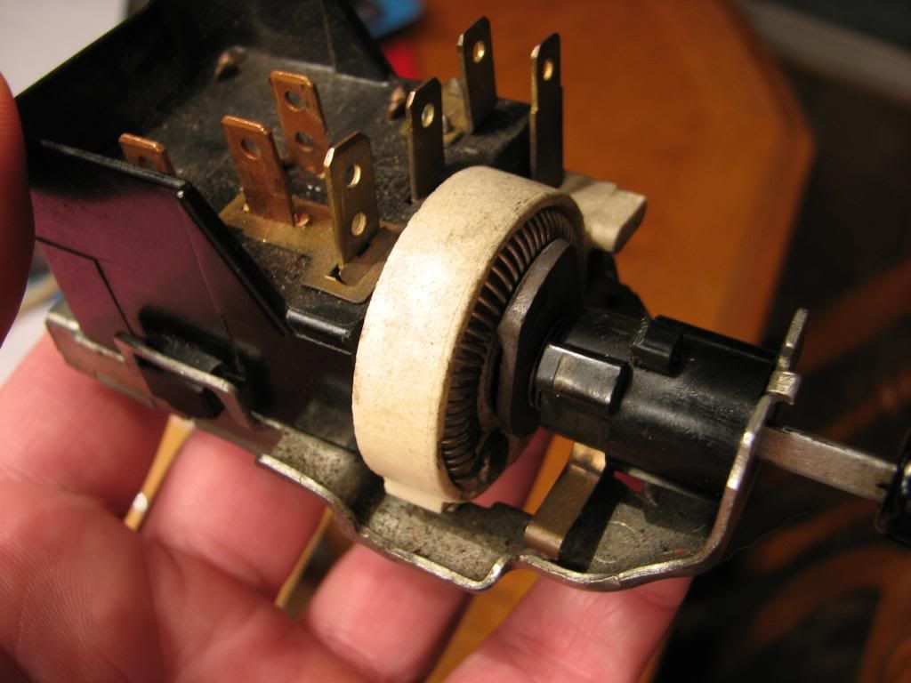
So I looked into it and the rheostat/resistor for the dash lights needs a big amperage load before I start seeing voltage drops that I could measure. My thought was to make some minor variations to the light switch to isolate the rheostat so I could just measure resistance. But how do I put that to use? I'm not an electrical engineer so hacking my little controllers that came with the LED strip lighting that do dimming didn't seem like it was going to get very far. So I looked around and came across something interesting called an "Arduino" board. I'm a programmer by trade and have always had interest in electronics. It's possible I could create a circuit, and tie it in with the Arduino, program it to do the Pulse Width Modulation (PWM) that does the actual dimming of LEDs. So I ordered an Arduino board for $12 from China. I have no idea how far I'll get with this, it's probably just more of a fun side project.
Anyways, that's my update for now. It's quite obvious this is going to take a lot more time that I originally thought. I'll keep updating when I can, but there will probably be some time between posts.

Since my Canon S3 IS is a bit low end for testing, I thought I'd try and be a bit more tech savvy and get me a LUX photometer. Seeing as I have no real use for a photometer outside of this testing, I was trying to be cheap and ordered a Pyle PLMT12 from Adorama for about $26 (+$3 shipping). Well it arrived last Friday and thought maybe I might be ready to start some limited testing. Well that came to a halt pretty fast when I took the meter out, put in a good 9V battery, and hit the On button. And nothing... dead, POS Chinese crap. So much for the nice "QC Passed" sticker on the back!!!
My idea is to tackle the 3 interior pieces:
#1 - speedo and tach
#2 - center cluster gauge
#3 - heater control
I'm still gathering up my ideas on what I want to do now that I have almost all of the materials that I want. To give you an idea of things that I'm working on I've taken some pictures of where I'm at. These aren't going to be my comparison pictures as I'll have to get my photometer working and a better setup, consider these just a teaser then.
Here's some nice, "warm white" LED strips I got off of eBay. My idea is that they would fit in-between the gauge face and reflection off the plastic housing.
If I was going to just stay with single color LEDs, this might be my choice for using in the speedo and tach. While I don't have LUX numbers for the 4 incandescent vs 4 LED 5050 (1894bulb) vs these strip lights, I must say they're very bright and fit in there almost perfectly without any cutting.
However after playing around with stuff, I'm pretty set upon my goal of having RGB LEDs that I can switch colors around when I want. I can certainly see why lots of people choose the blue LEDs as they really make the colors pop and leave the black background very black.
So in my quest for introducing RGB LEDs into my cluster, I began with how I would attach the speed and tach. While it seems that Atlanta Speedometer has taken down all links to their LED dash kit, I remember seeing it and thinking that's pretty neat idea. So how to replicate it? If you've never seen the kit, look around to see if you can find some pictures.
Since I needed to put some distance between the back can and the front plastic housing, I tried using some oven hardened clay that I formed. It didn't turn out that great and my pictures I just took were bad so I didn't even put them here. Next I tried some wood pieces I found at Michaels craft store that are probably used for needle point of some sort, 7" and 6" wood circles. I needed to cut them a bit and bend the inner one a bit with some boiling water. This is kind of what I was thinking of:
The wood strips are exactly the right width for my LED strips. My idea is to put the LED on the inside:
Trying to be a stickler for details, I found an issue. That issue is that the wood separator allows someone looking from the side to easily see my lights:
I think that would bother me after a while, knowing it's there. So I thought what about a diffuser on the inner circle of the plastic housing that would be painted black (or ultimately formed with black resin from a RTV mold) and would block the line-of-sight to the LEDs. So I worked on this:
That seems like it would work, but the materials for a RTV mold and the resin aren't cheap, and I'm not sure this is the ultimate direction I need to go.
So I thought about alternatives. How else could I get LEDs close to the rim of the speed/tach face and have it bounce off the plastic housing? Sure I could just stick 4 of the 1894 bulbs in the correct holes, add some reflector material, and call it a day, but you lose the ability to change colors. So I started thinking about something else and came up with this:
I bought some protoboard/perfboard from Radio Shack and had already ordered some Piranha superbright RGB LEDs from eBay. I also have a huge assortment of resistors on their way as well. I already have some nice radio frequency (RF), instead of infrared (IR), remotes for my LED strips in the opening set of pictures.
My idea would be to build my own ring that sits right behind the face plate and reflect off the plastic housing. The plastic housing would need some upgrades if I was to get maximum light reflection. So I've looked at getting some real titanium white paint and I've also actually bought some silver leaf that I could apply to the plastic. I'm not sure how that's all going to look yet as there's lots of work to be done before I get there.
I've also thought of things like how cool would it be to be able to dim my lights from my original switch which is something I often see listed as a minor gripe when changing over to LED bulbs:
So I looked into it and the rheostat/resistor for the dash lights needs a big amperage load before I start seeing voltage drops that I could measure. My thought was to make some minor variations to the light switch to isolate the rheostat so I could just measure resistance. But how do I put that to use? I'm not an electrical engineer so hacking my little controllers that came with the LED strip lighting that do dimming didn't seem like it was going to get very far. So I looked around and came across something interesting called an "Arduino" board. I'm a programmer by trade and have always had interest in electronics. It's possible I could create a circuit, and tie it in with the Arduino, program it to do the Pulse Width Modulation (PWM) that does the actual dimming of LEDs. So I ordered an Arduino board for $12 from China. I have no idea how far I'll get with this, it's probably just more of a fun side project.
Anyways, that's my update for now. It's quite obvious this is going to take a lot more time that I originally thought. I'll keep updating when I can, but there will probably be some time between posts.
02-09-2014, 07:13 AM
#6
Safety Car

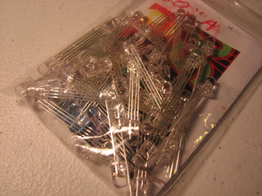
I like what you`re doing with the LEDs... and will follow this thread to watch as you go along. My son just bought a couple boxes of LED bulbs for his 74 Camaro. We "bench tested" one with a couple pieces of wire and a car battery.... it lit up the whole 1000 square foot garage! He got a couple bags of these on ebay....


 02-21-2014, 02:46 AM
#8
Burning Brakes
Thread Starter
I've still got a few things in the mail that will arrive by this weekend, such as my new Hakko soldering iron, and some orange LEDs for side marker testing.
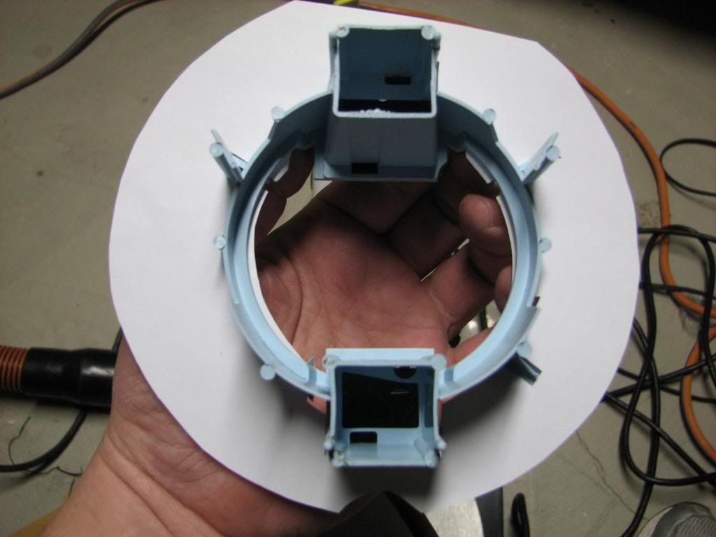
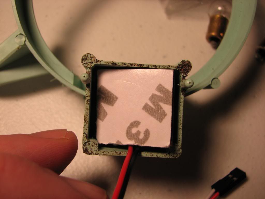
What I focused on today was getting my LED board, for the speedo/tach, ready to mount the LEDs. Here's a few pictures:
perfboard/PCB:
creating the paper template:
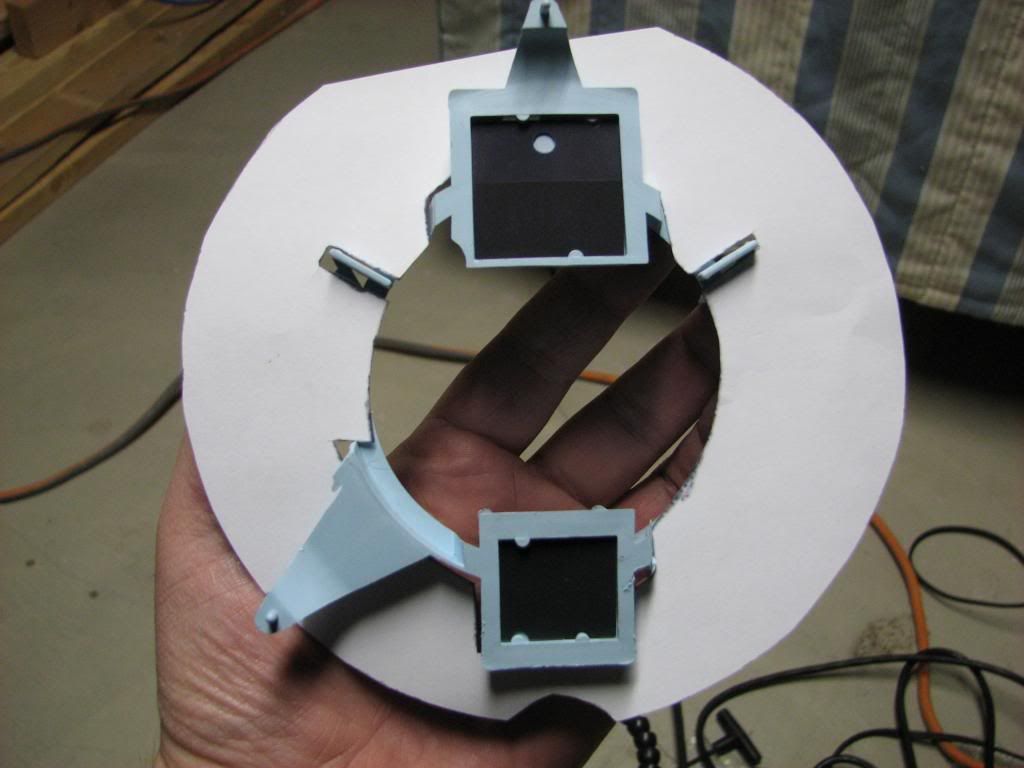
backside:
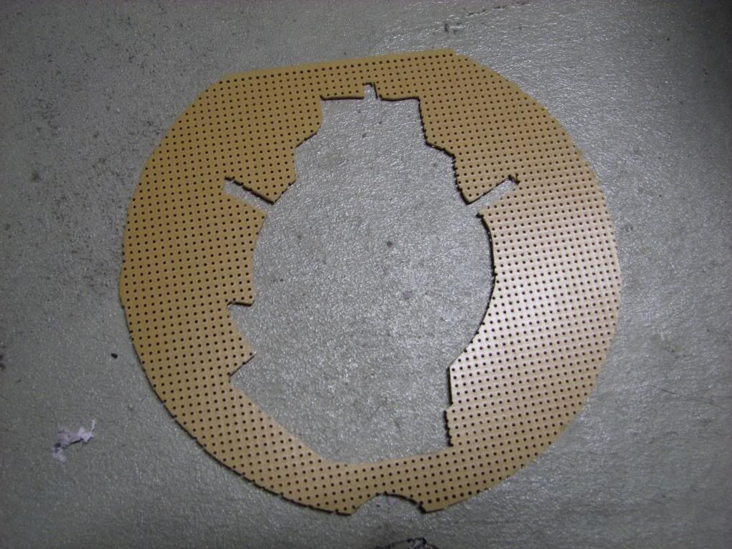
the cutout using my new scroll saw along with my horrible cutting skills:
mounting:
backside:
sideview:
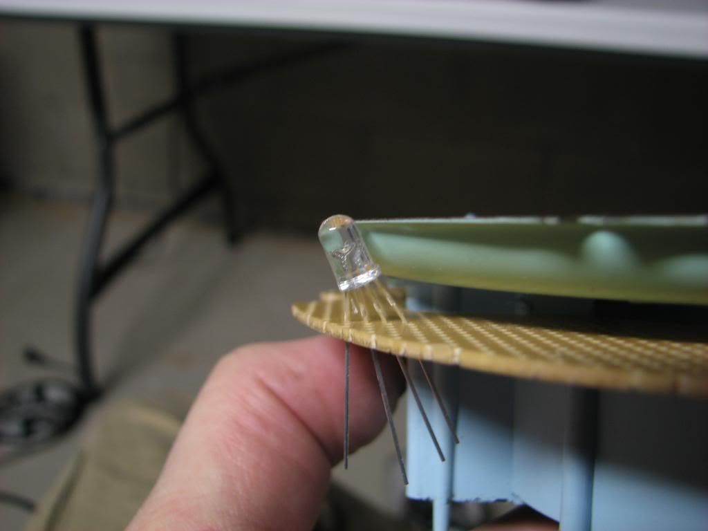
in the can, noting the flat spot at the top for the can indentation:
test fitting an LED at the appropriate angle:
What I focused on today was getting my LED board, for the speedo/tach, ready to mount the LEDs. Here's a few pictures:
perfboard/PCB:
creating the paper template:
backside:
the cutout using my new scroll saw along with my horrible cutting skills:
mounting:
backside:
sideview:
in the can, noting the flat spot at the top for the can indentation:
test fitting an LED at the appropriate angle:

 02-23-2014, 07:25 PM
#11
Burning Brakes
Thread Starter
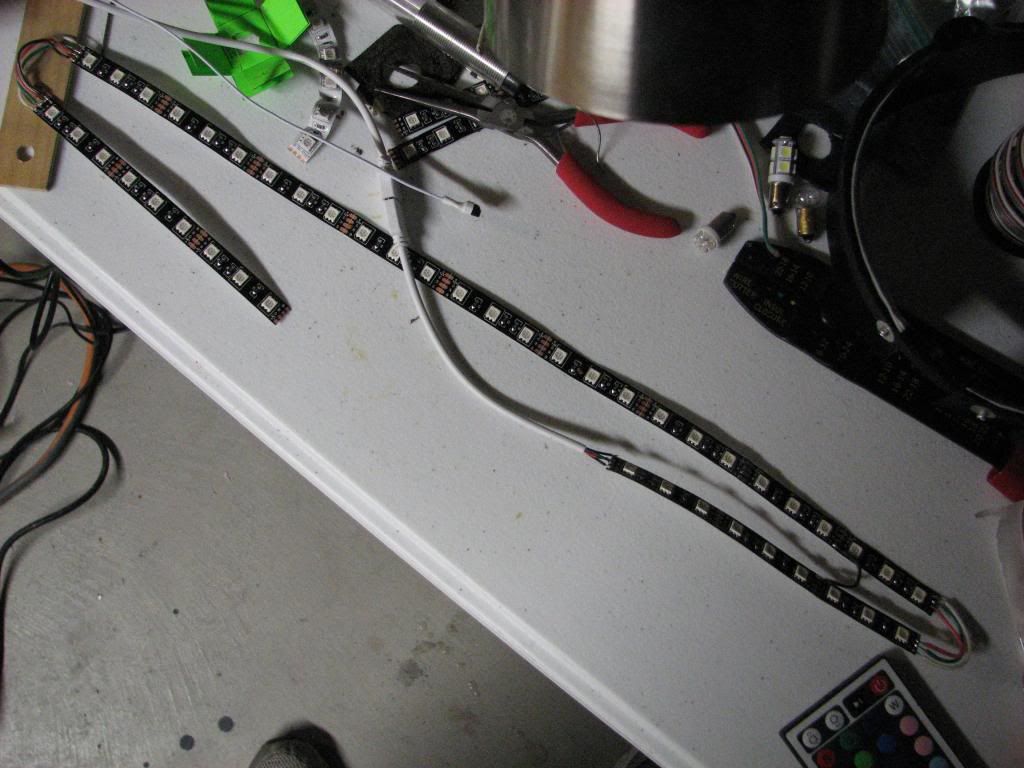
So after I ended my last posting, I got my Hakko soldering gun in the mail and that got me thinking of how I'm going wire this all up. The LEDs I planned on using there common anode RGB LEDs bought from eBay:
However, after researching all of the technical talk of how to wire these up, the best answer I could come up with is that each RGB LED cathode had to have its own resistor for safety. That meant each LED was going to have 3 resistors, multiply that times the number of LEDs I planned on using for my ring, and that number is more than I wanted to solder, plus thinking of all of the wasted heat those resistors would encounter instead of producing light got me thinking again. Was there a way to use the LED strip lighting I bought that uses the SMD LEDs instead? Those RGB LEDs using SMT (Surface Mount Technology) seemed like the way to go as each SMD LED was like having 3 separate LEDs in one package, each with it's own anode/cathode. That means that you can easily wire these suckers up in series.
But the question was how do you make a straight LED strip conform to my round ring?
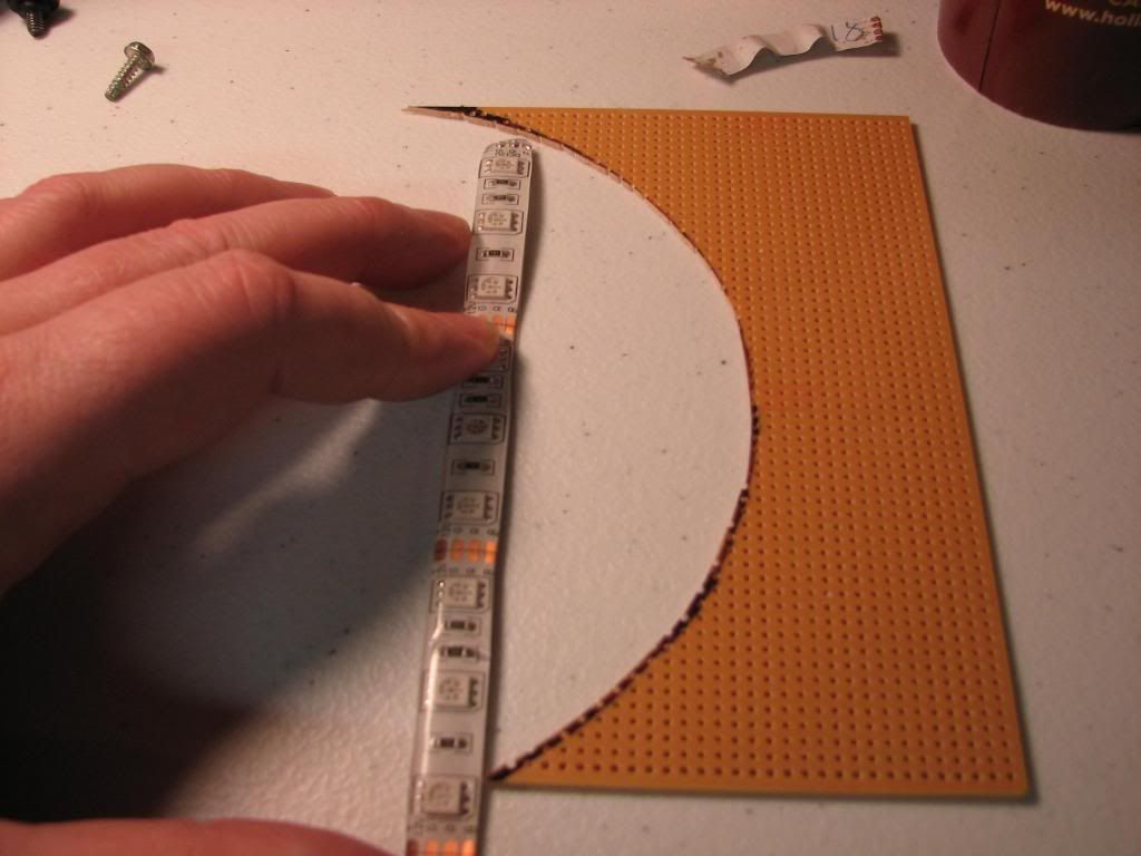
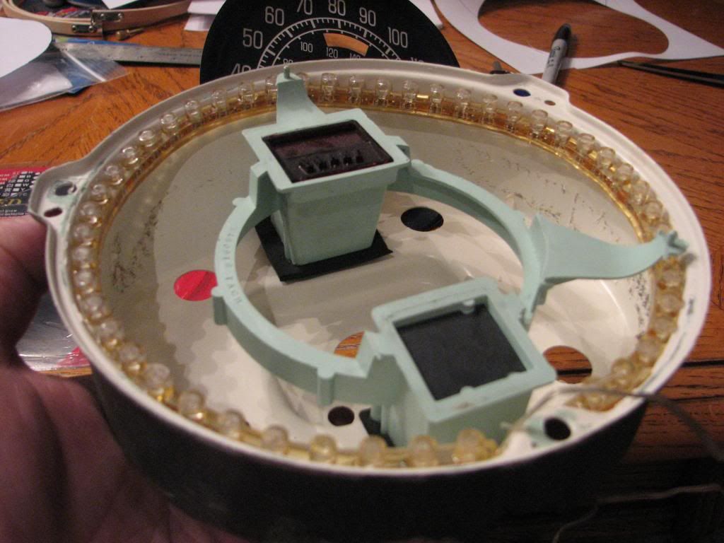
You can't just simply bend it around or else the light shines sideways:
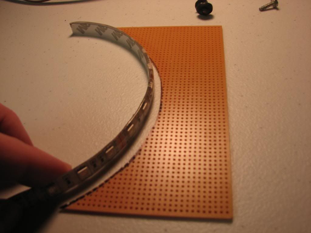
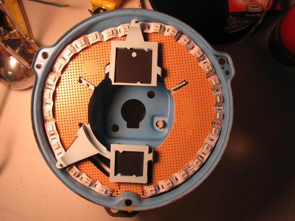
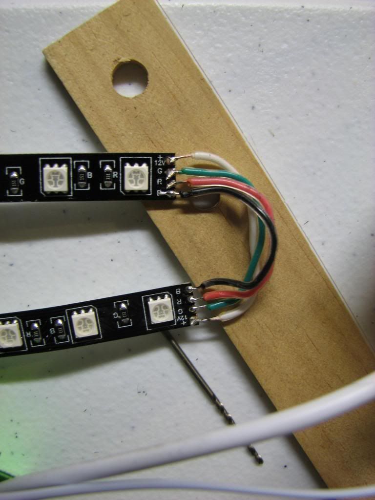
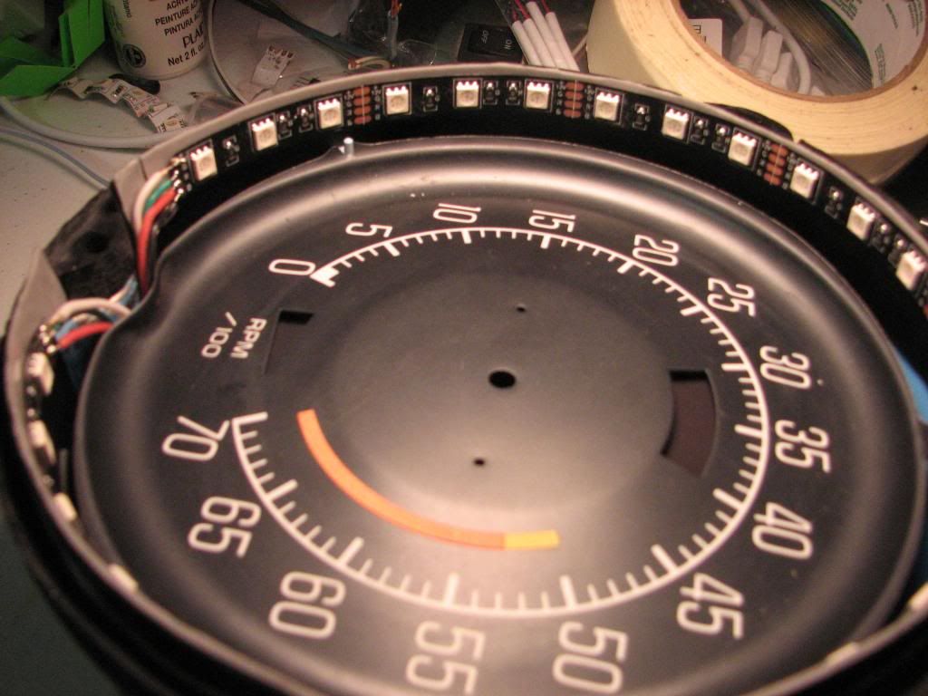
Then it hit me last night as I was playing around with the strip. Like a great sci-fi movie, I had to think in the 3rd dimension. That's how I ended up with this:
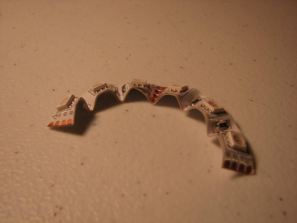
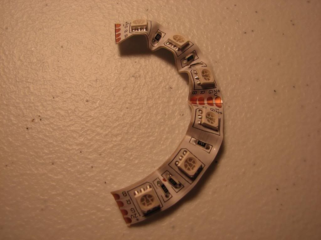
That little trick might seem obvious to some, but it took me a while. Not only does it make my led strip curve to my ring, but it also has the added benefit of slightly angling the LEDs towards the outside so that instead of hitting the back of the face, more light goes to the plastic housing. Brilliant.
This is what I ended up with:
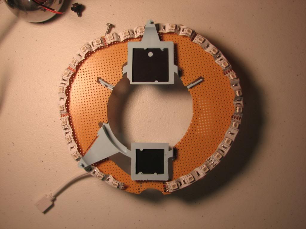
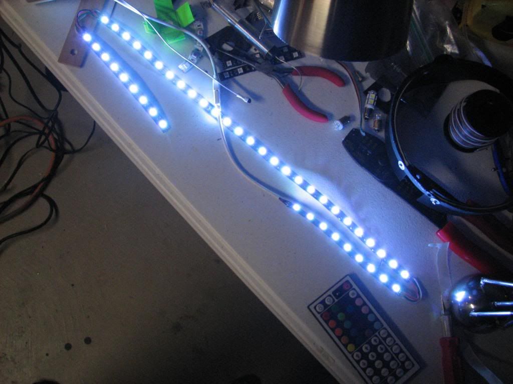
A little test to make sure it was working:
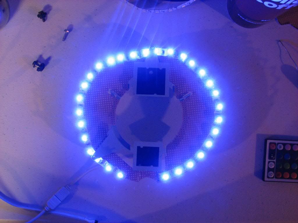
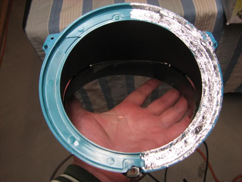
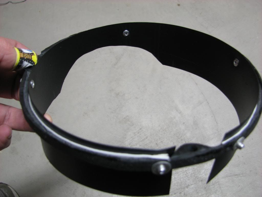
Stick it in the can:
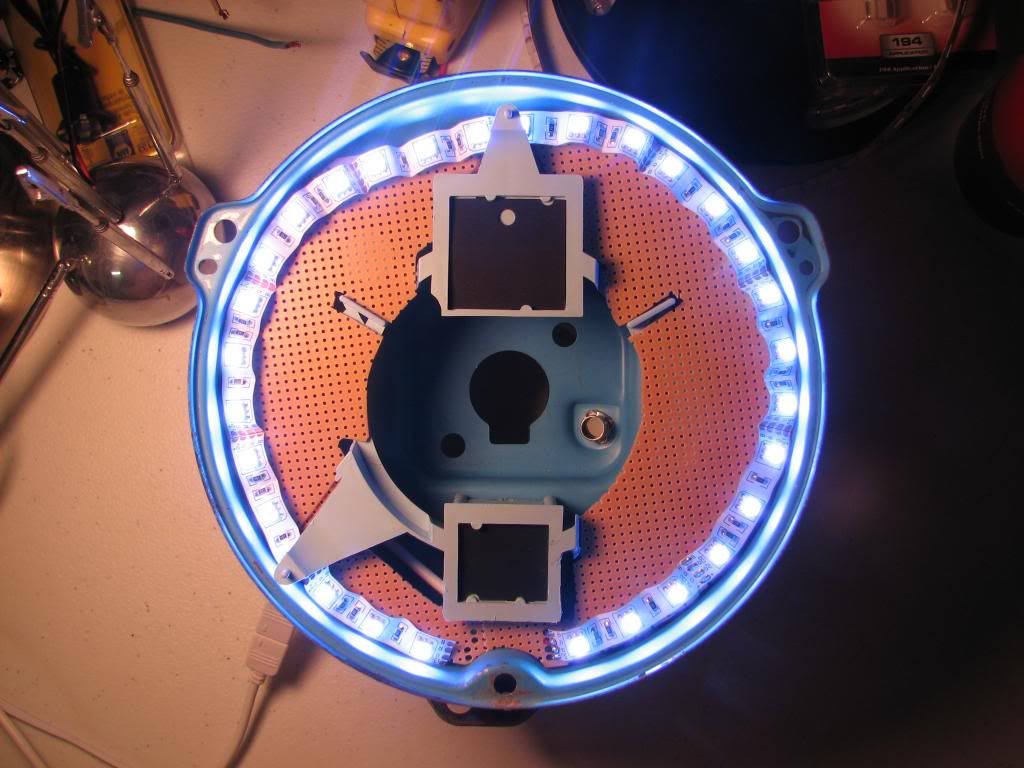
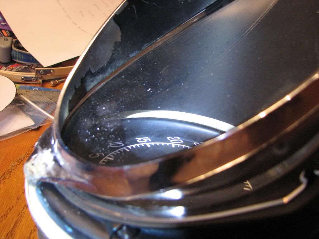
If you read my earlier postings, you'd remember I bought some foil. I figured that since I want the brightest display I can get, I need something better than titanium white paint to reflect my light back onto the gauge face. So I took some rubber cement (so I could later remove it, for testing only) and hastily put on some silver leaf foil on 1/2 of the plastic housing so that I could gauge whether or not it made a difference in the amount of light reflected off of it.
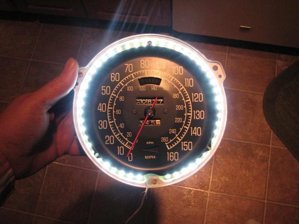
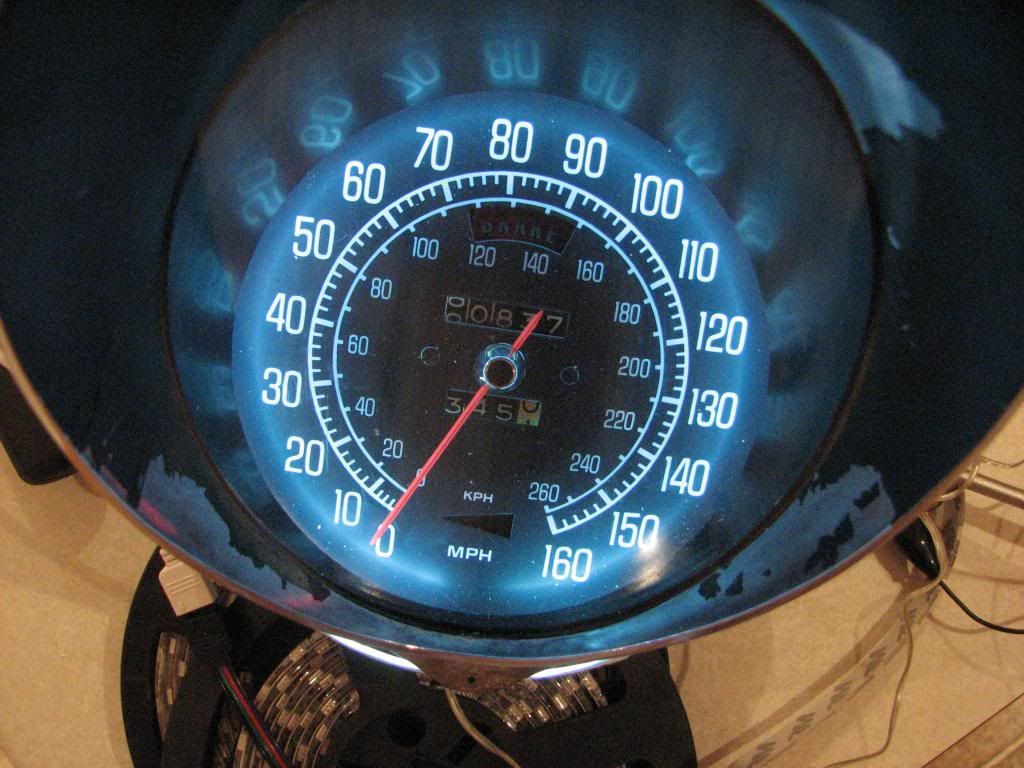
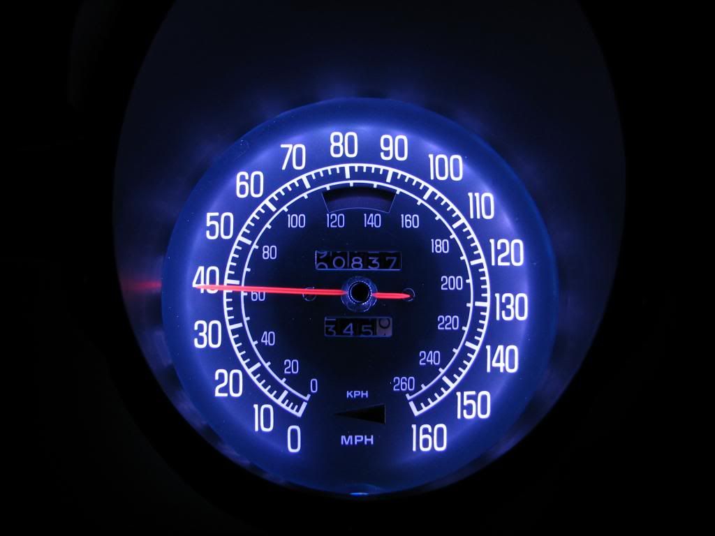
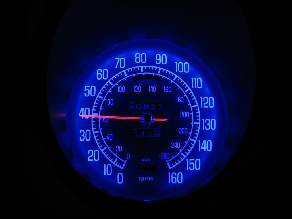
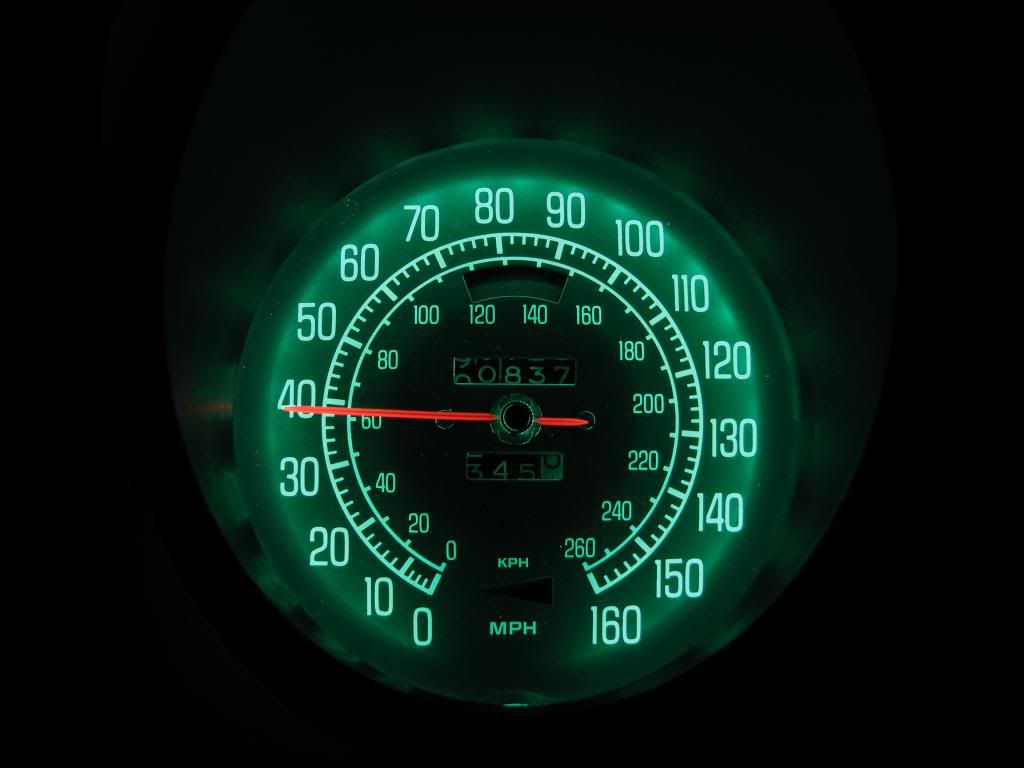
So onto some sample shots of each color that my remote control offers. I've edited the photo to include a key such as: R1, G3, B5, W2, so that you can match up the photo with the color on the remote:
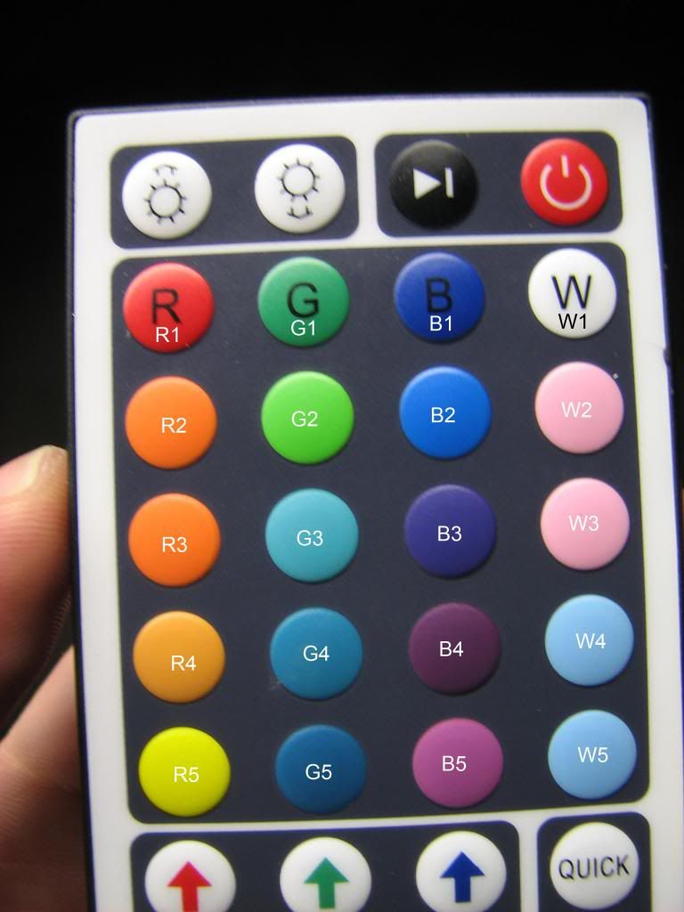
As you look at these pictures, note the different levels in brightness of the left half versus the right half. That's because of the silver leaf foil I added. I think most will agree that it makes a fairly substantial difference.
R1:
G1:
B1:
W1:
R2:
G2:
B2:
W2:
R3:
G3:

B3:

W3:
R4:
G4:
B4:
W4:
R5:
G5:
B5:
W5:

I have a bit more work to do before I start getting my LUX meter out to do some light emission readings and compare them to the incandescent bulbs, but I'm close. I've got to figure out a way to get my led to stick to my PCB board, thinking about clear silicone, not sure yet. I also need to address adding a 3 LED strips on each side of the inner housing to illuminate the odometer/trip display.
I took
with my Canon S3 IS, it's fairly grainy but thought I'd include it nonetheless.
So lots more to come, getting there as fast as I can.
A quick shot of my workplace in my freezing basement so that I could get all of my crap off the dinner table as my wife didn't like that too much:
However, after researching all of the technical talk of how to wire these up, the best answer I could come up with is that each RGB LED cathode had to have its own resistor for safety. That meant each LED was going to have 3 resistors, multiply that times the number of LEDs I planned on using for my ring, and that number is more than I wanted to solder, plus thinking of all of the wasted heat those resistors would encounter instead of producing light got me thinking again. Was there a way to use the LED strip lighting I bought that uses the SMD LEDs instead? Those RGB LEDs using SMT (Surface Mount Technology) seemed like the way to go as each SMD LED was like having 3 separate LEDs in one package, each with it's own anode/cathode. That means that you can easily wire these suckers up in series.
But the question was how do you make a straight LED strip conform to my round ring?
You can't just simply bend it around or else the light shines sideways:
Then it hit me last night as I was playing around with the strip. Like a great sci-fi movie, I had to think in the 3rd dimension. That's how I ended up with this:
That little trick might seem obvious to some, but it took me a while. Not only does it make my led strip curve to my ring, but it also has the added benefit of slightly angling the LEDs towards the outside so that instead of hitting the back of the face, more light goes to the plastic housing. Brilliant.
This is what I ended up with:
A little test to make sure it was working:
Stick it in the can:
If you read my earlier postings, you'd remember I bought some foil. I figured that since I want the brightest display I can get, I need something better than titanium white paint to reflect my light back onto the gauge face. So I took some rubber cement (so I could later remove it, for testing only) and hastily put on some silver leaf foil on 1/2 of the plastic housing so that I could gauge whether or not it made a difference in the amount of light reflected off of it.
So onto some sample shots of each color that my remote control offers. I've edited the photo to include a key such as: R1, G3, B5, W2, so that you can match up the photo with the color on the remote:
As you look at these pictures, note the different levels in brightness of the left half versus the right half. That's because of the silver leaf foil I added. I think most will agree that it makes a fairly substantial difference.
R1:
G1:
B1:
W1:
R2:
G2:
B2:
W2:
R3:
G3:
B3:
W3:
R4:
G4:
B4:
W4:
R5:
G5:
B5:
W5:
I have a bit more work to do before I start getting my LUX meter out to do some light emission readings and compare them to the incandescent bulbs, but I'm close. I've got to figure out a way to get my led to stick to my PCB board, thinking about clear silicone, not sure yet. I also need to address adding a 3 LED strips on each side of the inner housing to illuminate the odometer/trip display.
I took
So lots more to come, getting there as fast as I can.
A quick shot of my workplace in my freezing basement so that I could get all of my crap off the dinner table as my wife didn't like that too much:
Last edited by StingrayLust; 02-23-2014 at 07:42 PM.
02-23-2014, 07:57 PM
#12
Burning Brakes
Thread Starter
I forgot to include this in my previous post.
I had found these LED rings which are almost exactly what I'd like to end up with. They're BMW angel eyes LED rings:
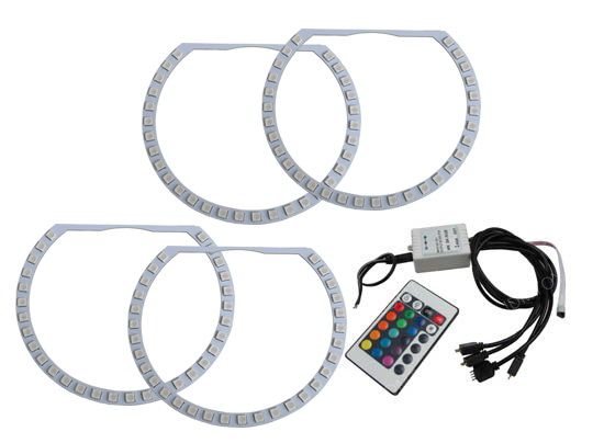
I couldn't find any dimensions for them but doubt they'd fit perfect, plus the flat spot without LEDs isn't optimal. However something like this is really where I'd like to get to.
The kit shown is only around $80. When I looked into creating my own schematic wiring layout for a custom PCB, at places like this, it was about $180 for 3 rings. Not exactly cheap but not so pricey either. The software you can download for free on some sites. My problem would be that paying $180 for the PCB my first time out only to find out I screwed up my design.
I guess if there was huge interest from some others on this board, we could split up the cost. I know there's probably some electrical engineers on this site, maybe they'd step forward and design a simple SMD LED PCB board we could order. The positive thing about this design is that creating one for SMD LEDs isn't exactly that hard. But that only gets me the PCB board, I'd need to get a SMD rework soldering station as getting the SMD LED chips on there is a lot more intricate.
I had found these LED rings which are almost exactly what I'd like to end up with. They're BMW angel eyes LED rings:
I couldn't find any dimensions for them but doubt they'd fit perfect, plus the flat spot without LEDs isn't optimal. However something like this is really where I'd like to get to.
The kit shown is only around $80. When I looked into creating my own schematic wiring layout for a custom PCB, at places like this, it was about $180 for 3 rings. Not exactly cheap but not so pricey either. The software you can download for free on some sites. My problem would be that paying $180 for the PCB my first time out only to find out I screwed up my design.
I guess if there was huge interest from some others on this board, we could split up the cost. I know there's probably some electrical engineers on this site, maybe they'd step forward and design a simple SMD LED PCB board we could order. The positive thing about this design is that creating one for SMD LEDs isn't exactly that hard. But that only gets me the PCB board, I'd need to get a SMD rework soldering station as getting the SMD LED chips on there is a lot more intricate.
02-24-2014, 01:33 AM
#13
Burning Brakes
Thread Starter
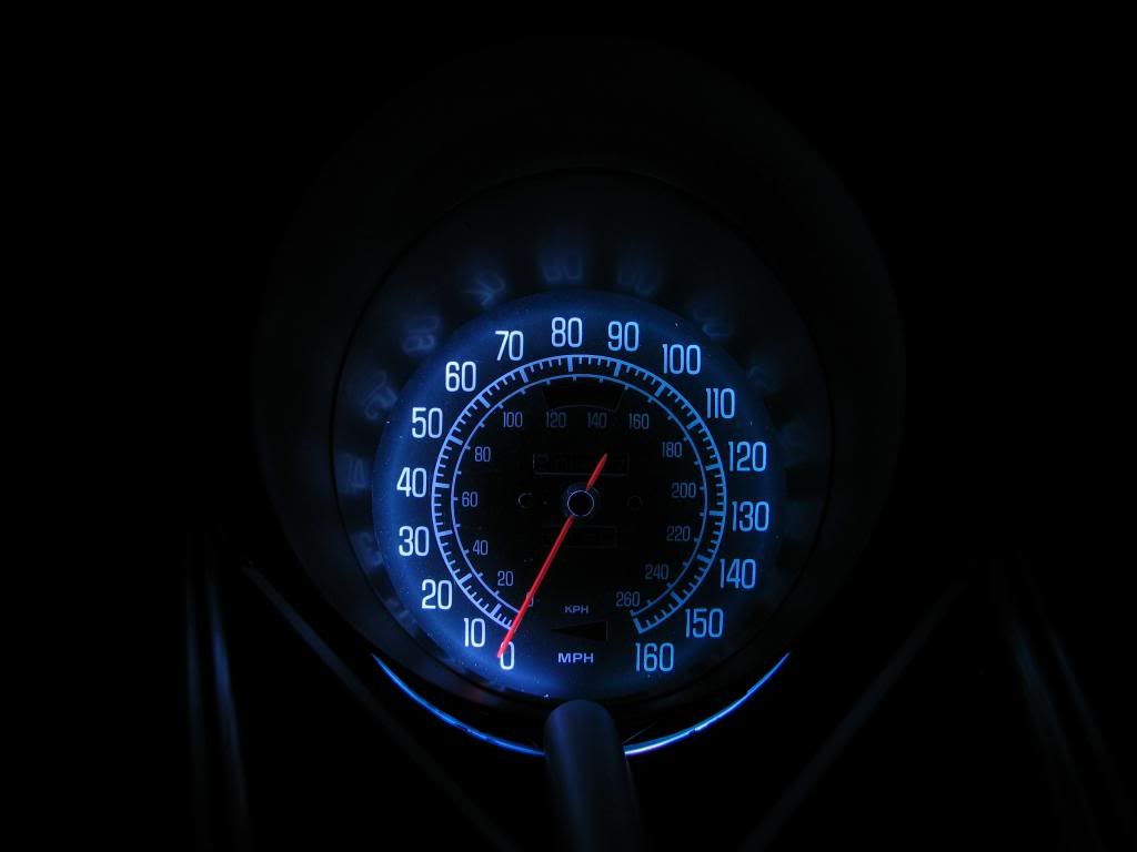
A reason to use the dimmer? Maybe.
Try as I might, I cannot get my poor little Canon S3 IS camera to take an exact shot of what my eye sees. For this test, I set the camera to full manual:
F-stop: f/3.5
Exposure time: 1/13 sec.
Exposure bias: 0 step
Focal length: 6mm
Max aperature: 2.875
Metering mode: center weighted
Even then my camera would never capture exactly what I see.
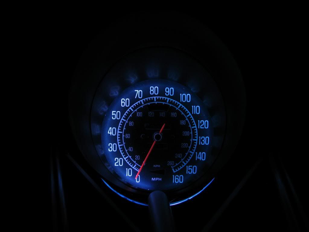
For this test I used the LED pure White settings (or as white as the RGB mix will get) at full brightness all the way to the dimmest setting my controller will allow. Even at the dimmest setting, the foil side shows some reflection in the black paint areas that my naked eye just doesn't see. I'll chalk it up to the 2 different technologies.
So from brightest to dimmest (8 different levels):
#1:

#2:
#3:
#4:
#5:

#6:
#7:

#8:
I then edited the photos to take some letters from the brightest and dimmest of the foil to compare to the brightest and dimmest of the non-foil side:
Maybe if I had a better camera who knows if it would show better what I actually see vs. what's in the pictures. I think I remember reading other members posting photos and having the same issue that the pictures didn't match up with what their eyes were seeing.
Being here I'll say that the foil side has the advantage in that I can dim them if I feel there is too much reflection. The White is exceptionally washed out in the photos (not my eye though) compared to the Reds and Blues, that's where the extra brightness of the foil, I think, makes it worth it.

Try as I might, I cannot get my poor little Canon S3 IS camera to take an exact shot of what my eye sees. For this test, I set the camera to full manual:
F-stop: f/3.5
Exposure time: 1/13 sec.
Exposure bias: 0 step
Focal length: 6mm
Max aperature: 2.875
Metering mode: center weighted
Even then my camera would never capture exactly what I see.
For this test I used the LED pure White settings (or as white as the RGB mix will get) at full brightness all the way to the dimmest setting my controller will allow. Even at the dimmest setting, the foil side shows some reflection in the black paint areas that my naked eye just doesn't see. I'll chalk it up to the 2 different technologies.
So from brightest to dimmest (8 different levels):
#1:
#2:
#3:
#4:
#5:
#6:
#7:
#8:
I then edited the photos to take some letters from the brightest and dimmest of the foil to compare to the brightest and dimmest of the non-foil side:
Maybe if I had a better camera who knows if it would show better what I actually see vs. what's in the pictures. I think I remember reading other members posting photos and having the same issue that the pictures didn't match up with what their eyes were seeing.
Being here I'll say that the foil side has the advantage in that I can dim them if I feel there is too much reflection. The White is exceptionally washed out in the photos (not my eye though) compared to the Reds and Blues, that's where the extra brightness of the foil, I think, makes it worth it.
03-02-2014, 07:23 PM
#14
Burning Brakes
Thread Starter
I decided to start some "official" testing with pictures and my LUX photometer today. I'm starting off with what seems like the easiest test to do, the emergency brake and turn signal lights in the speedometer face.
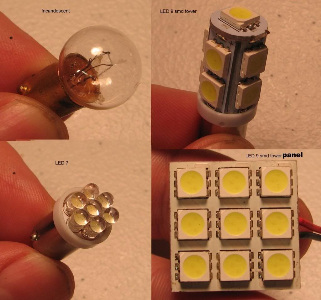
Here are the light bulbs I test with:
A picture of all 4 of them:
For the photos, I took all of them in manual mode with my Canon PowerShot S3 IS:
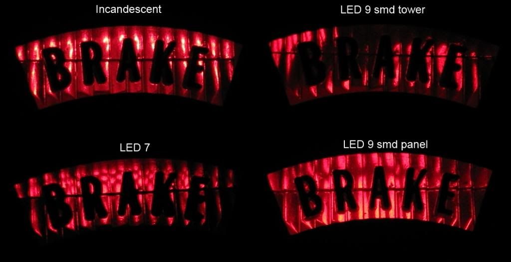
I took light meter readings from both the red, emergency brake indicator:
Here's the image comparison:
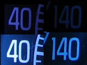
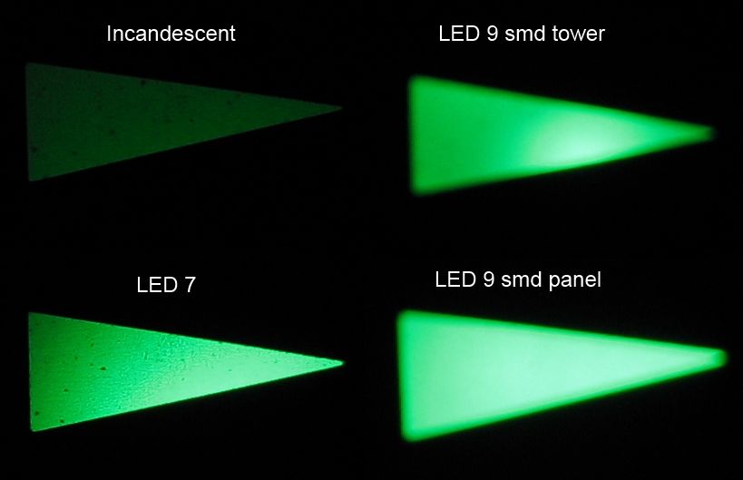
I also took lux readings from the green, turn signal indicator:
The image comparison for the turn signal:
Some Notes:
The red brake indicator was a bit tough to photograph as when you change the angle left/right or up/down the brightness changes. I tried to take the photo at the brightest angle I could get, all from the same height. My guess as to why the 9 smd tower wasn't that bright was that the very top LED was pointing not directly at the back of the housing instead of shining through the semi-transparent portion. That's because it was the tallest of all of the bulbs tested. The green was slightly the same as I angled the housing to get the brightest shot/reading.
I think most would agree that the 9 smd panel was the clear winner in brightness as well as delivering the best viewing angle brightness. The smd panel is about 0.88" in width and height, just barely making it fit into the housing. I plan on making a bracket for it to sit nicely inside the housing.
Here's what I'm thinking of doing for the center gauge cluster lighting, still working on the layout:
Anyways, I hope you found this worthwhile. I'll get to the other testing when I get time.

Here are the light bulbs I test with:
- 1895 incandescent
- 1895 LED 9 smd tower
- 1895 LED 7
- 1895 LED 9 smd panel
A picture of all 4 of them:
For the photos, I took all of them in manual mode with my Canon PowerShot S3 IS:
F-stop: f/2.7
Exposure time: 1/160 second
ISO: 80
Metering mode: Pattern
Exposure time: 1/160 second
ISO: 80
Metering mode: Pattern
I took light meter readings from both the red, emergency brake indicator:
- incandescent:______6 lux
- LED 9 smd tower :__1.2 lux
- LED 7 :___________2 lux
- LED 9 smd panel :__3.2
Here's the image comparison:
I also took lux readings from the green, turn signal indicator:
- incandescent:______5 lux
- LED 9 smd tower :__39 lux
- LED 7 :___________60 lux
- LED 9 smd panel :__92
The image comparison for the turn signal:
Some Notes:
The red brake indicator was a bit tough to photograph as when you change the angle left/right or up/down the brightness changes. I tried to take the photo at the brightest angle I could get, all from the same height. My guess as to why the 9 smd tower wasn't that bright was that the very top LED was pointing not directly at the back of the housing instead of shining through the semi-transparent portion. That's because it was the tallest of all of the bulbs tested. The green was slightly the same as I angled the housing to get the brightest shot/reading.
I think most would agree that the 9 smd panel was the clear winner in brightness as well as delivering the best viewing angle brightness. The smd panel is about 0.88" in width and height, just barely making it fit into the housing. I plan on making a bracket for it to sit nicely inside the housing.
Here's what I'm thinking of doing for the center gauge cluster lighting, still working on the layout:
Anyways, I hope you found this worthwhile. I'll get to the other testing when I get time.
 04-29-2014, 02:52 AM
#16
Burning Brakes
Thread Starter
It's been a while since I've posted anything here, my job, putting in manual pedals in my '71, choosing a transmission, and life in general has gotten in the way. But I've made a push these last 10 days to make some progress.
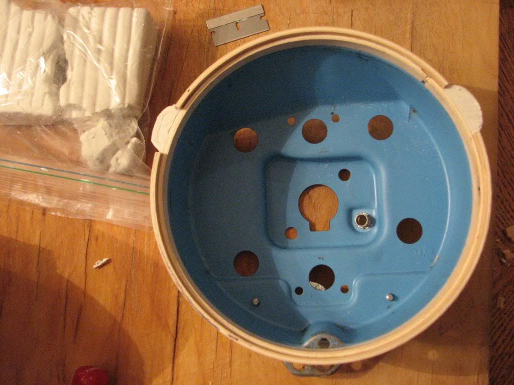
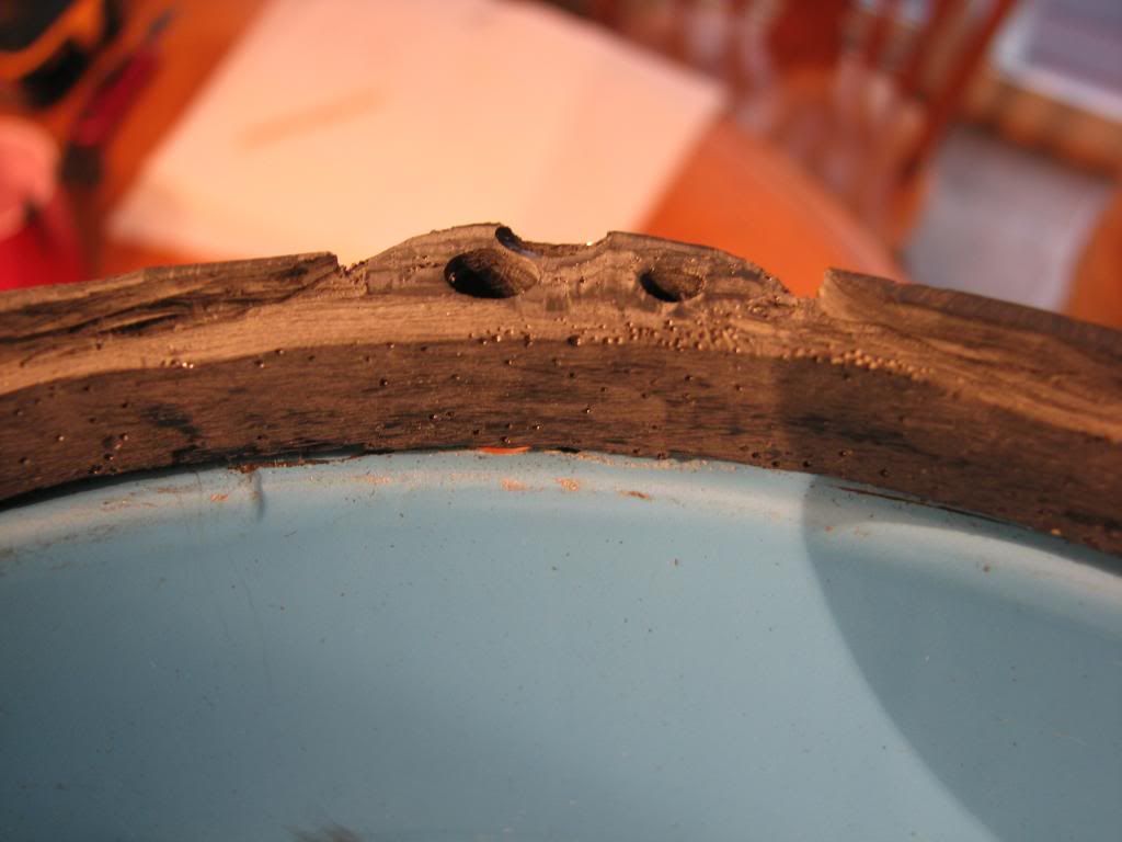
I decided to go with my wood ring concept and fabricate some kind of housing. The goal was to allow the most light to reach the surface of the gauge as well as require little to no modifition of the housings. I think I'm pretty close.
So I started off at Michaels craft store of all places picking up some wooden rings that I think they use for crochet.
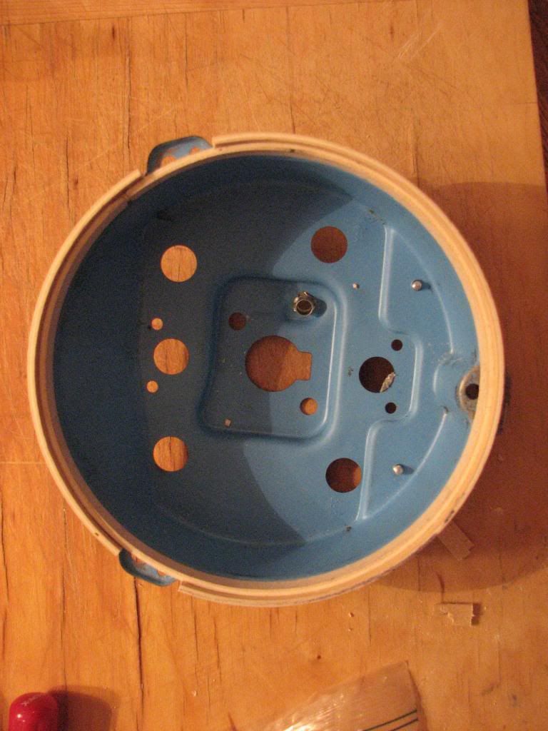
and then using some hardening modeling clay, create the flange supports:
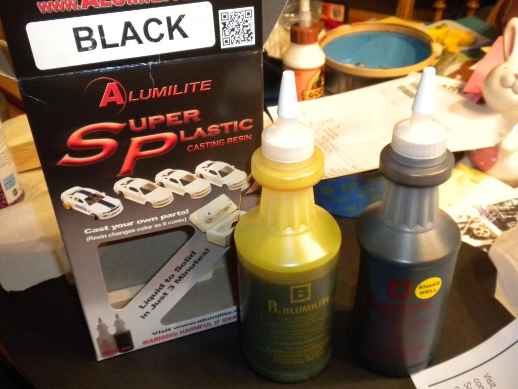
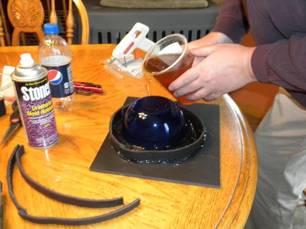
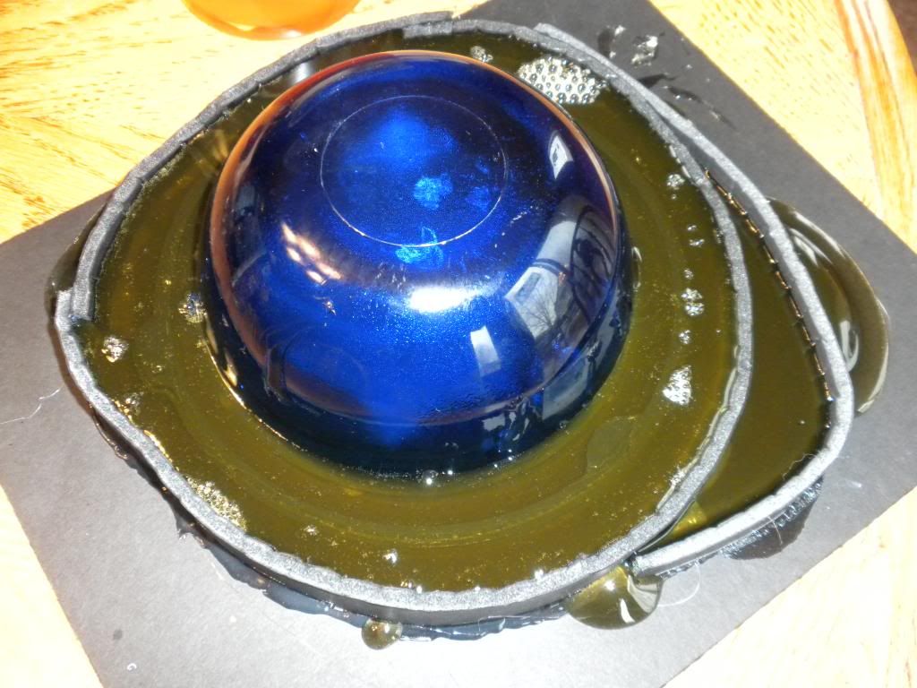
Once I had all of that ready, I decided I'd try my hand at making a mold. Now since I was doing this on a shoestring budget, I didn't get to use silicone for my mold, instead I used a product called Composimold that you can reuse over and over just by reheating it and making a new mold, plus the fact that I could get 40oz for about $36, silicone is a lot pricier for a one time use and the first time out. Then I needed some plastic and decided to go with black Aluminilite Casting Resin which by itself wasn't cheap at around $65:
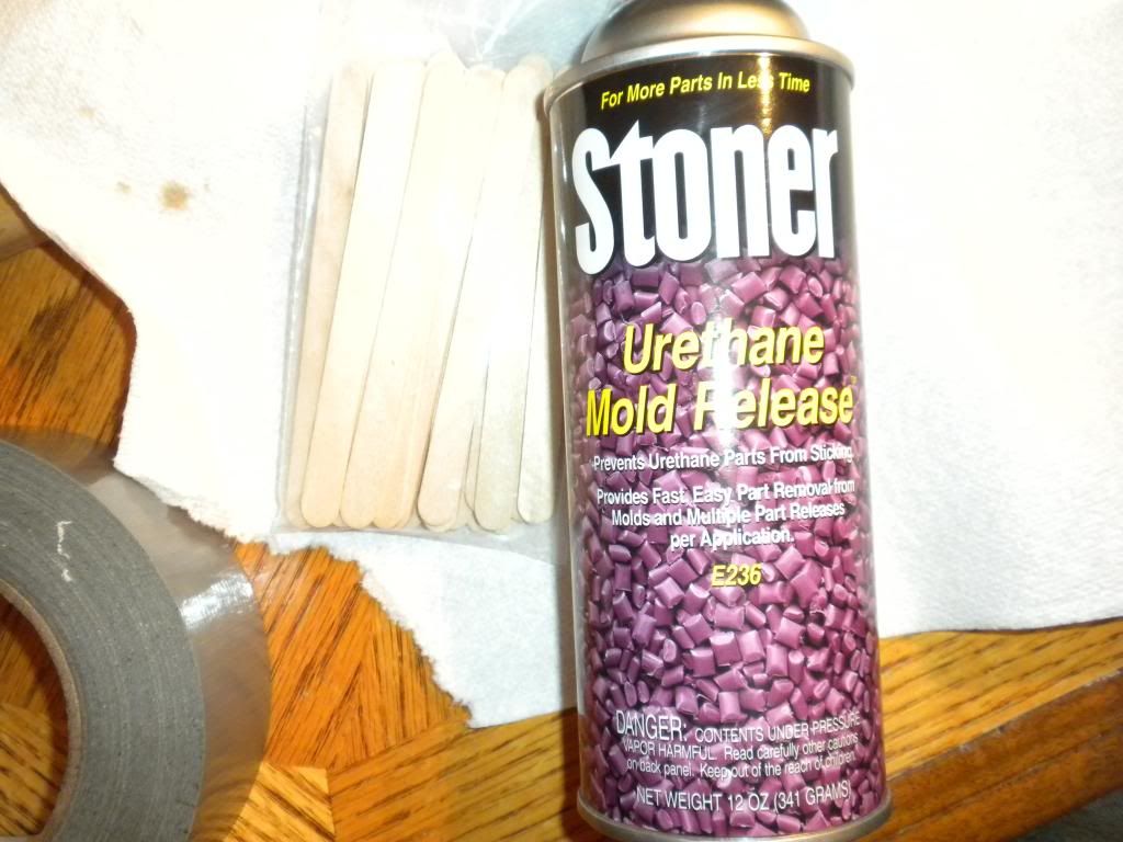
I also bought some mold release:
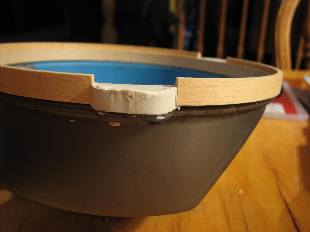
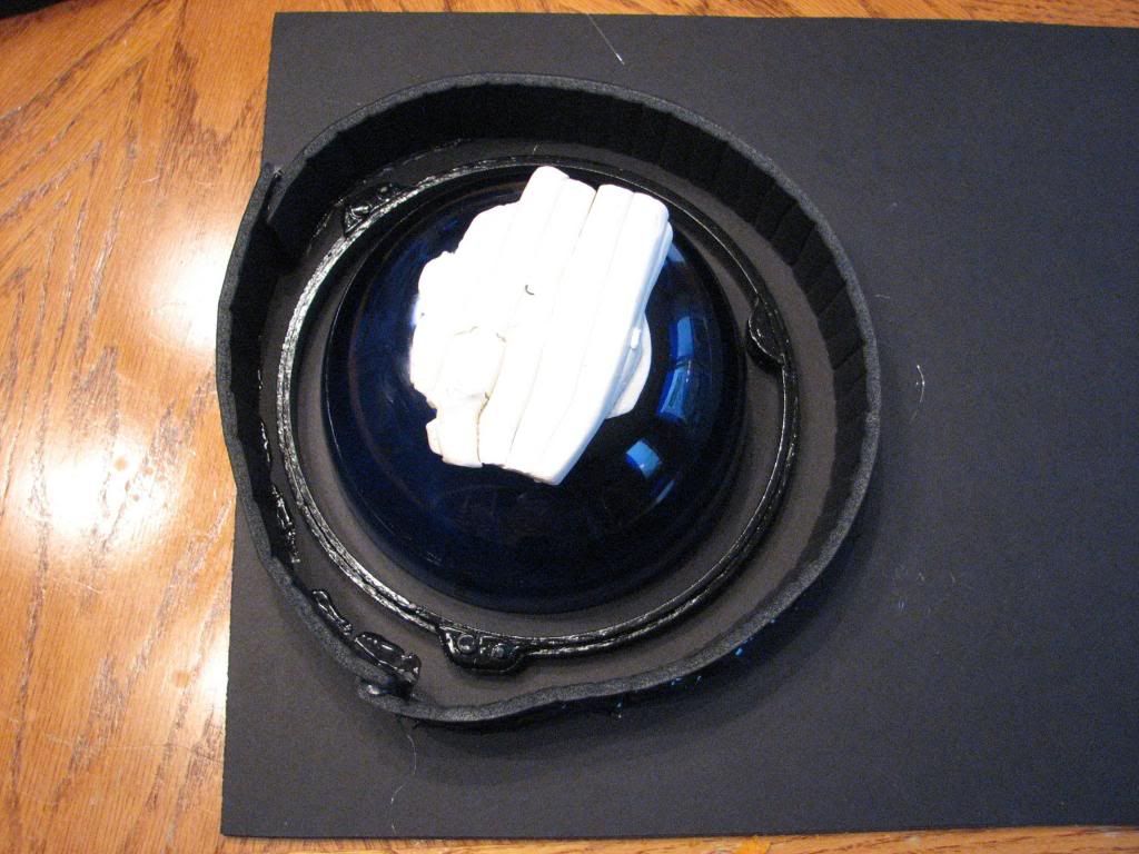
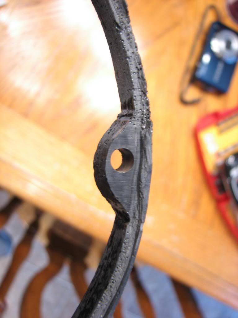
So here's my wood and clay prototype ready for molding:
I then proceeded to make a molding structure to pour the Composimold into:
I then had to let it cool. As you can see I didn't hot glue the inside at all and ended up with a few leaks:
I then took apart the mold structure and removed my wood/clay prototype from the mold.
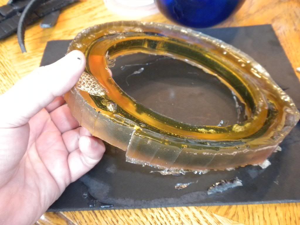
Next up I mixed up the plastic resin according to the instructions and poured into my mold:
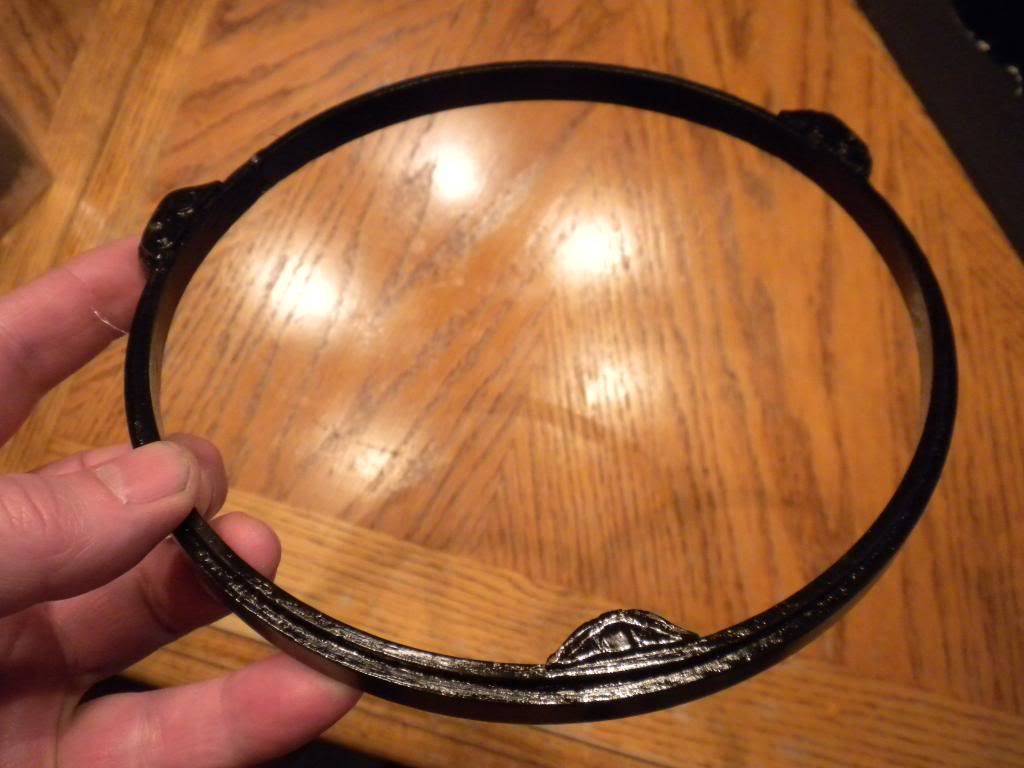
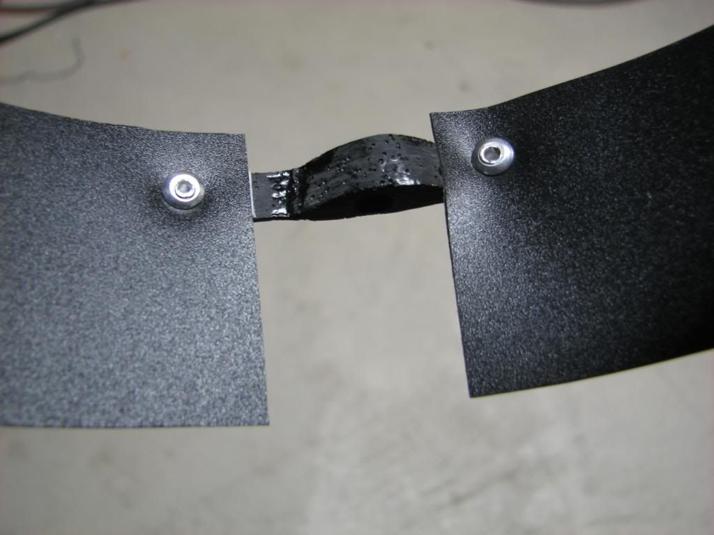
It only takes a couple minutes for the plastic resin to cure after which I can then remove my casting. Here it is with casting flash that needs to be trimmed.
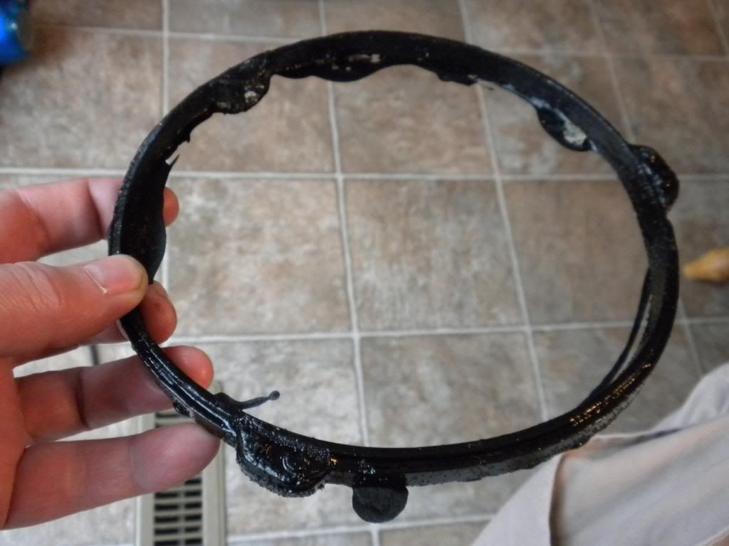
Now back one second to my comment about using Composimold vs silicone, the quality of the casting was rather poor and I ended up with a lot of bubbles in my casting. However, I didn't buy the correct "bubble buster" that you're supposed to use with Composimold so that most likely had a negative effect.
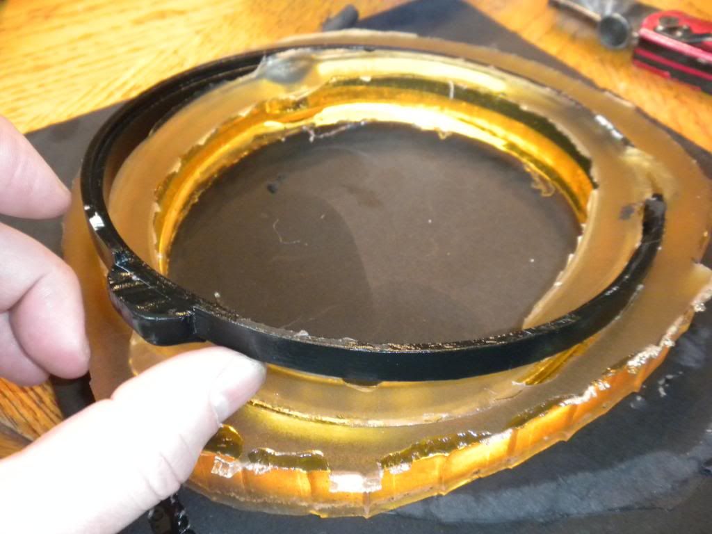
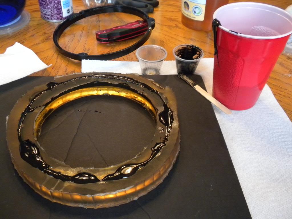
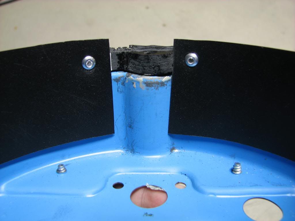
So I took the part to my sander/grinder and tried to clean it up a bit:
At this point I'm ready to make my LED strip that will be mounted inside my newly cast piece:
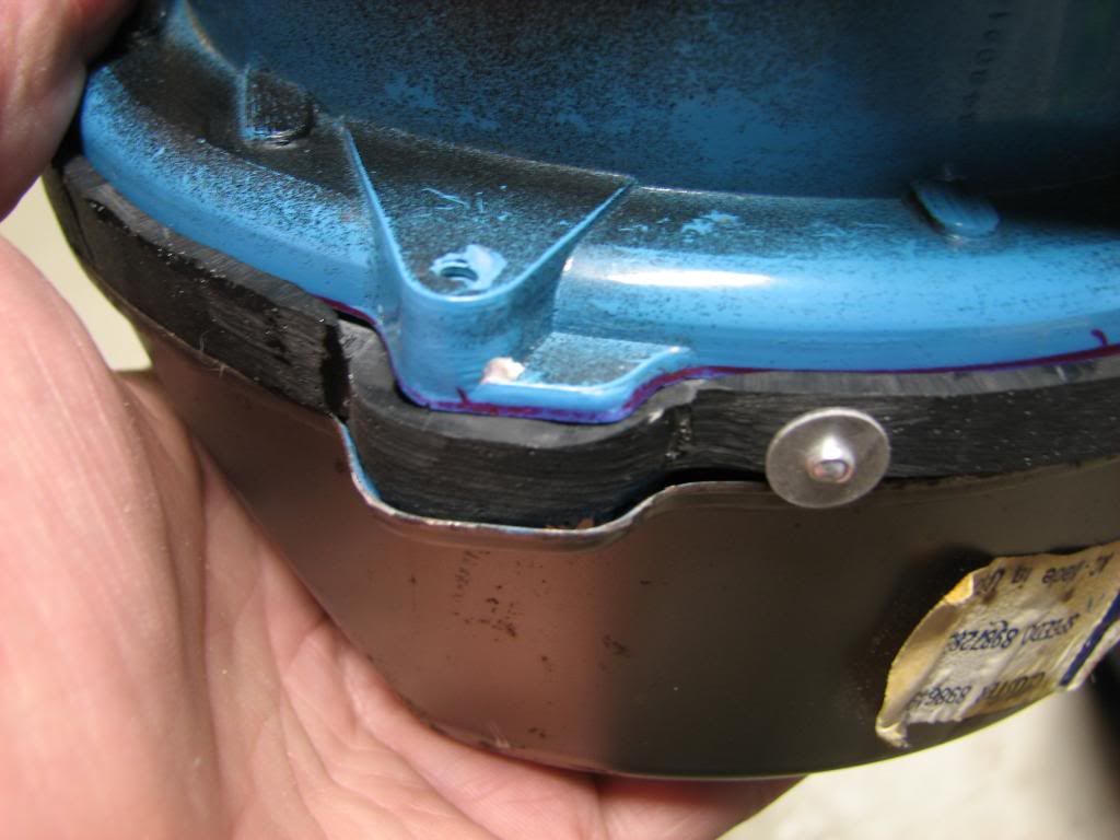
I added some plastic surround to the inside of the cast piece to allow more room for the top housing to fit into the groove as well as hide the outside of the can that's now possible to see since I've raised up the entire top part of the housing. This plastic surround was just fashioned out of a cheap plastic binder I bought at Walmart for like $1.
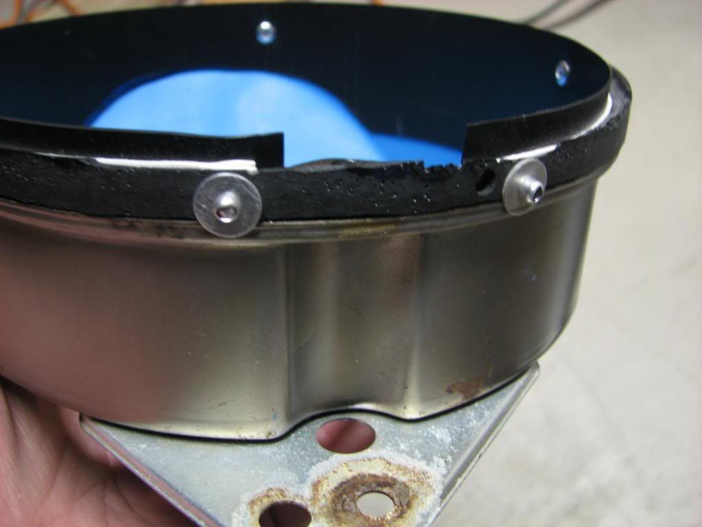
Even though I thought my double-sided tape would work well, I decided to use some pop rivets to secure it in place:
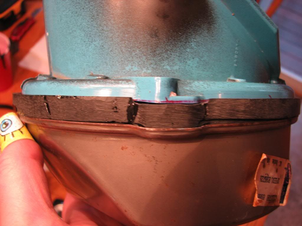
Test fitting the piece, obviously not perfect:
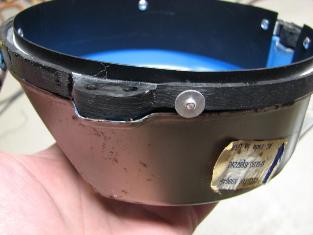
Now I just had to mount the LED strip I soldered together using more double-sided tape. I may use some sort of epoxy glue later on.
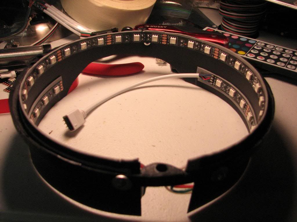
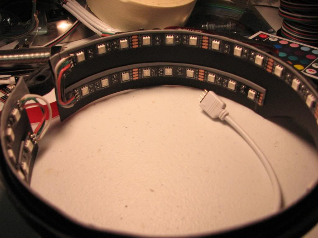
Now you may ask, why the two rows of LEDs? The reason is that the top row is to luminate the surface of the gauge, but the bottom row will help illuminate the odometer and trip wheels. Overkill? Maybe, but I wanted to do this as correctly as I could.
Putting it all together:
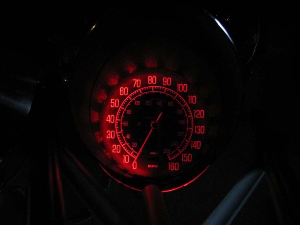
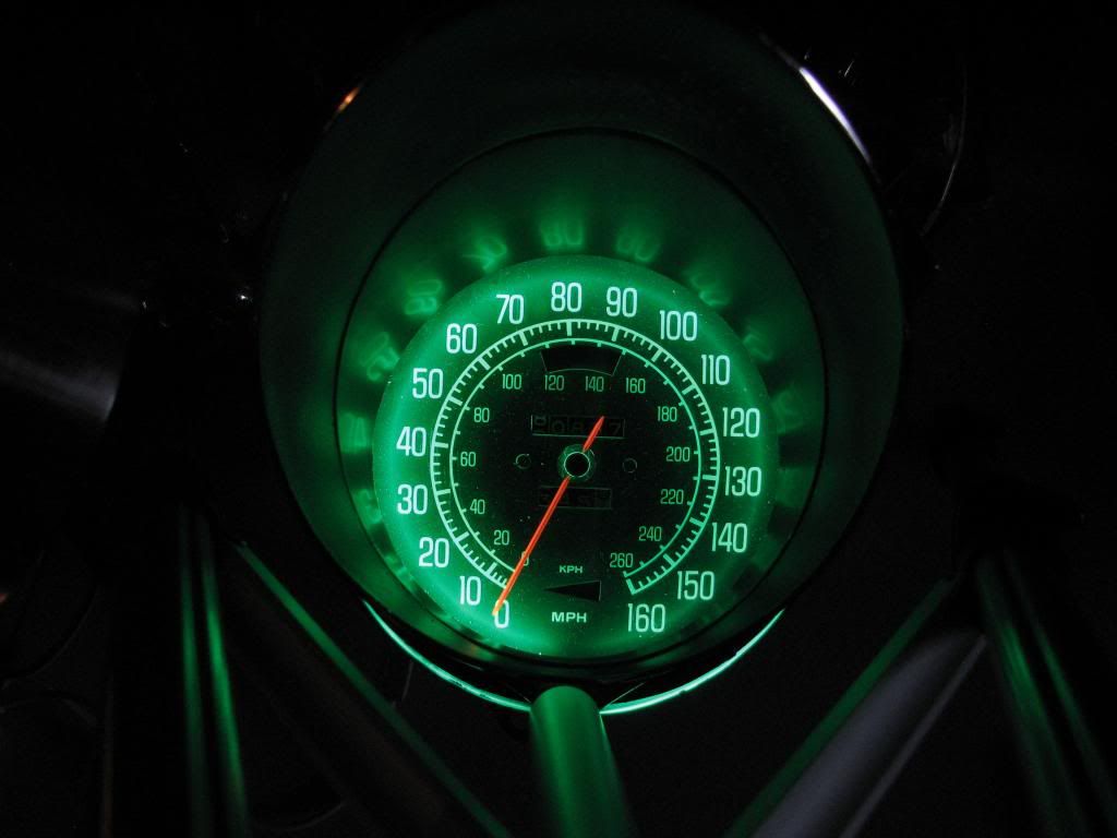
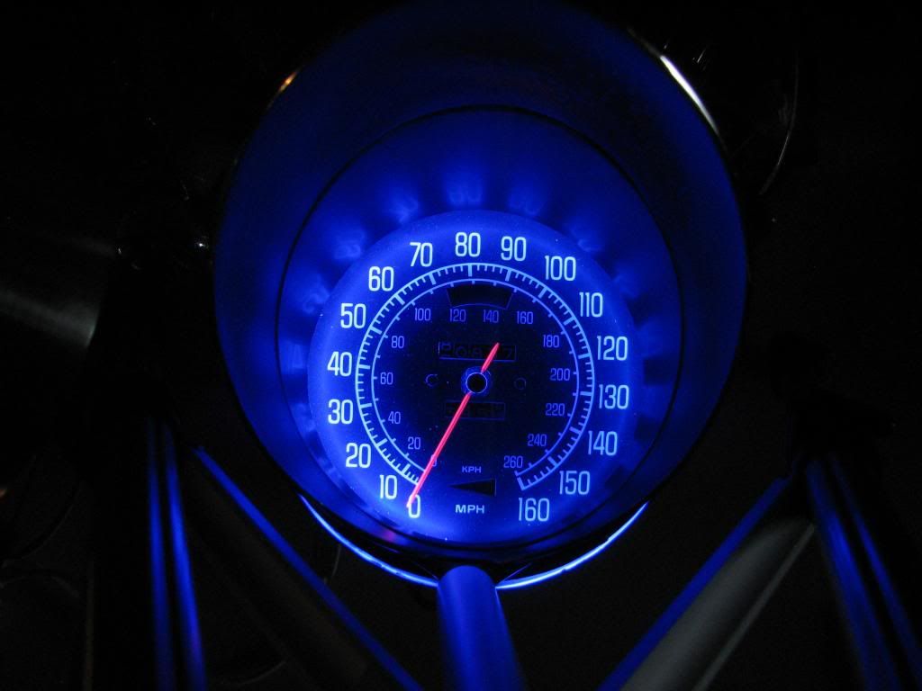
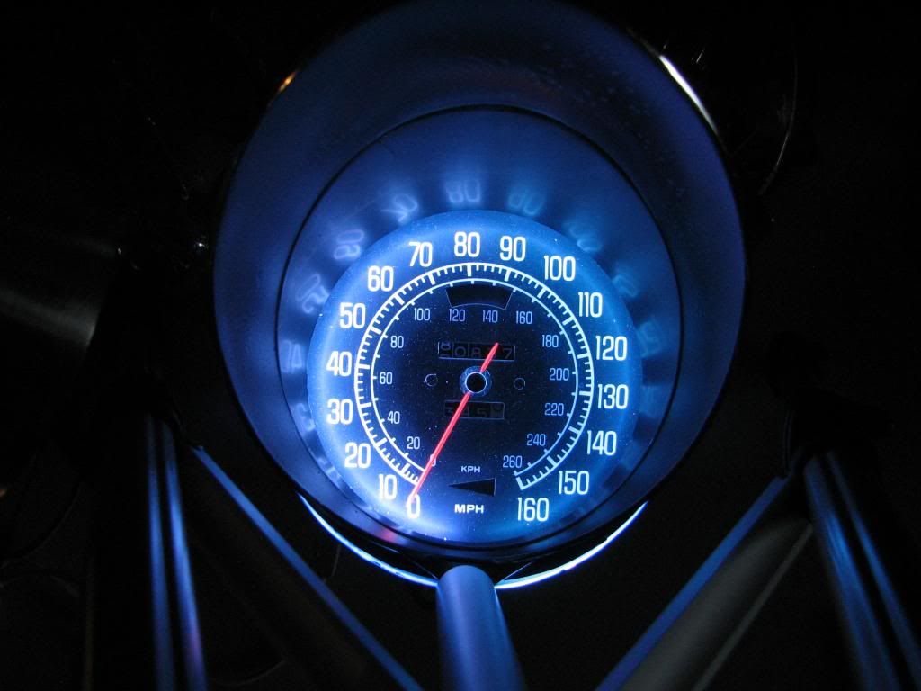
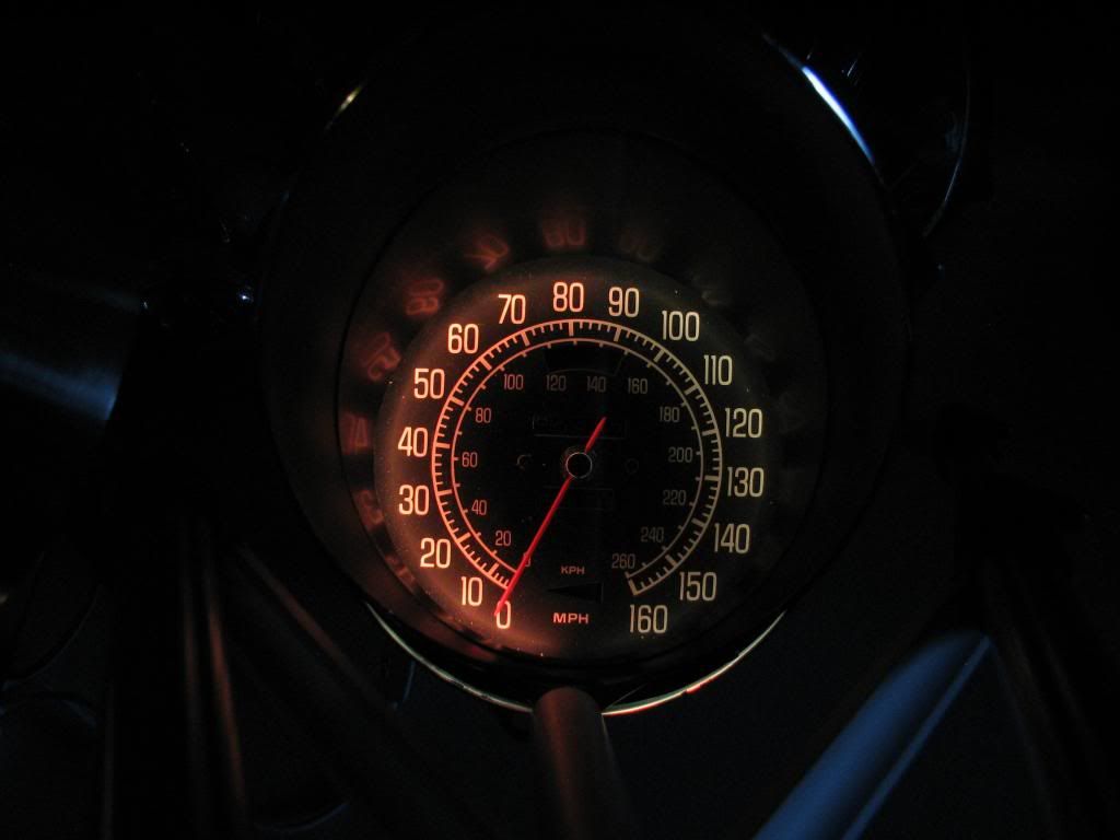
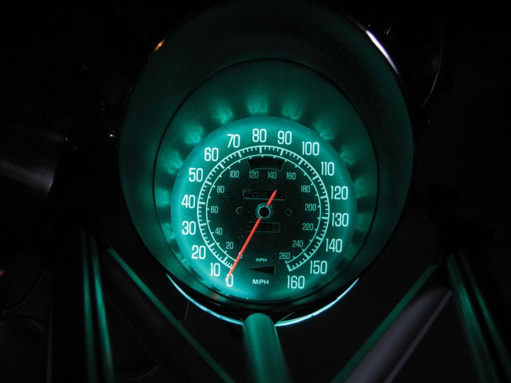
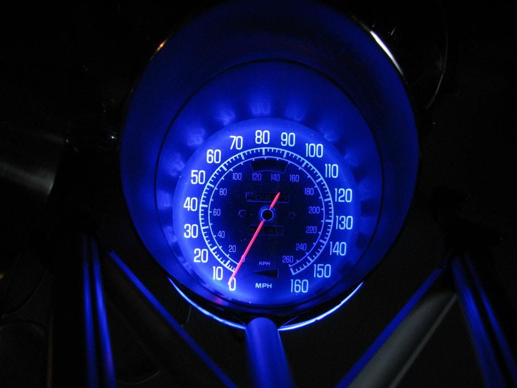
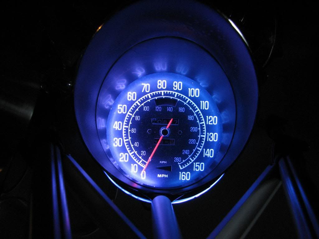
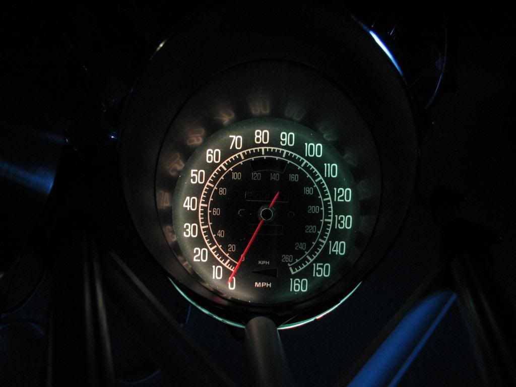
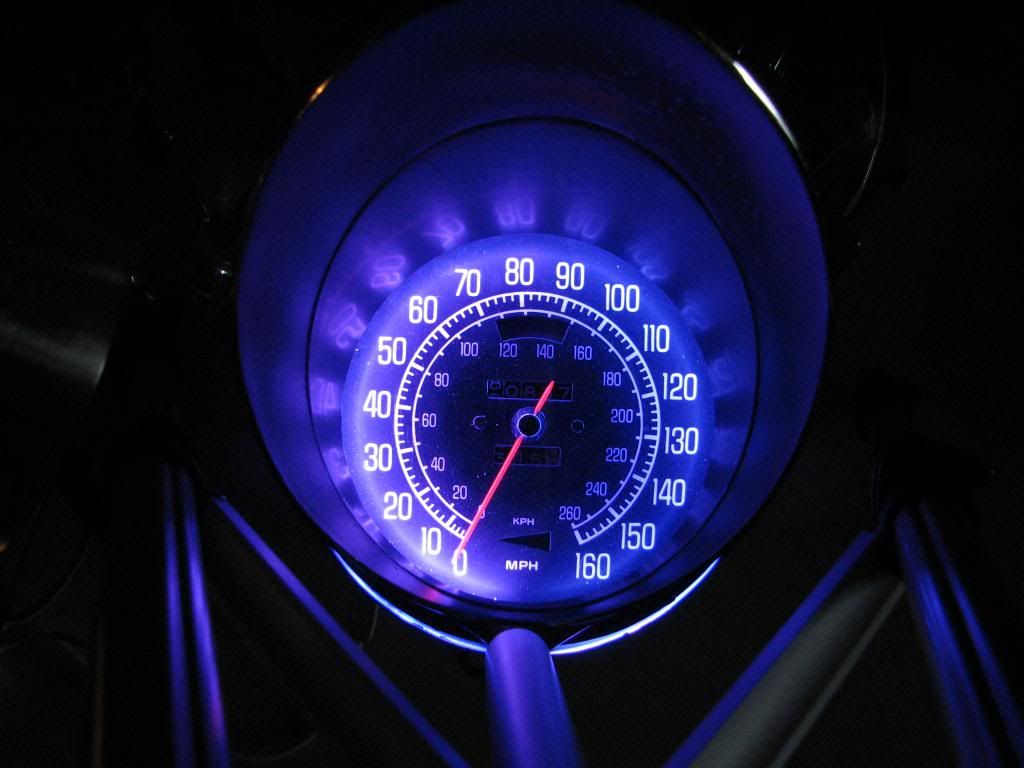
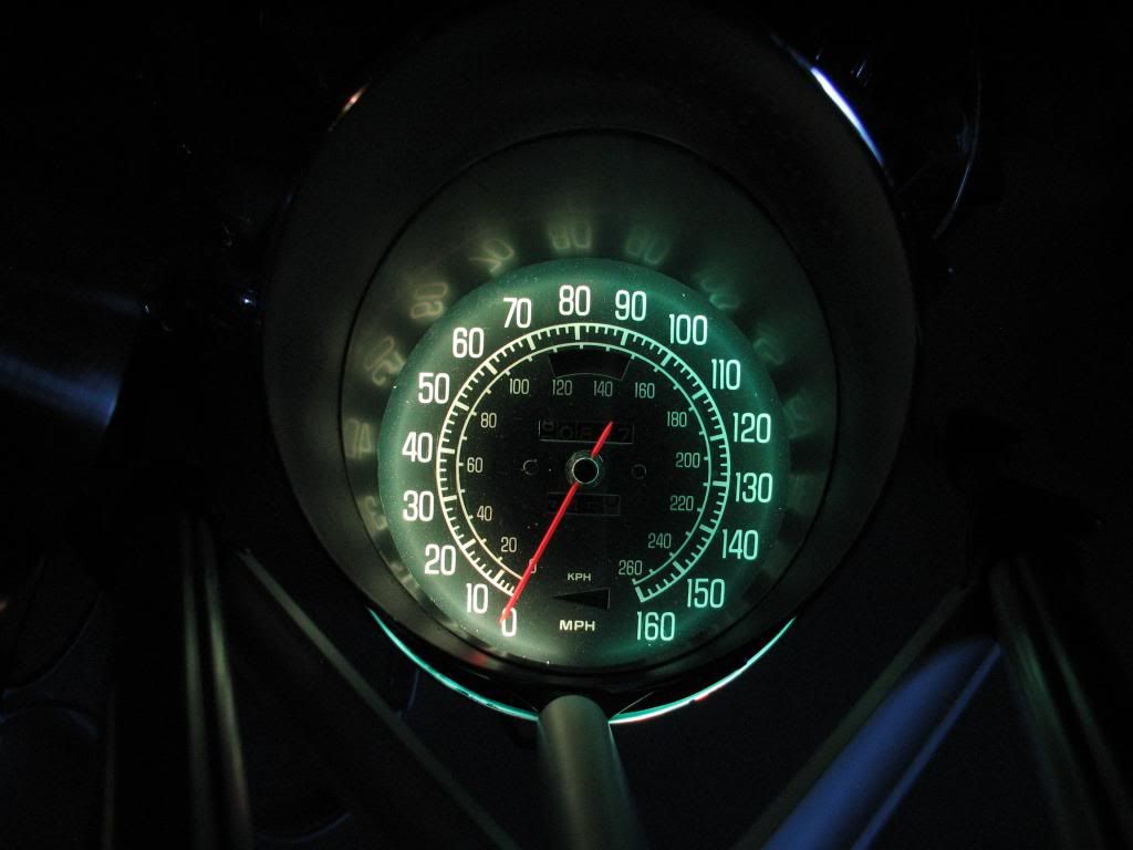
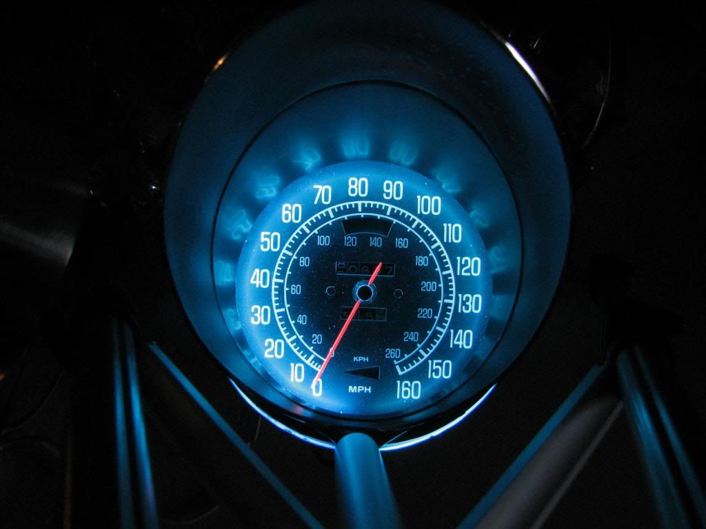
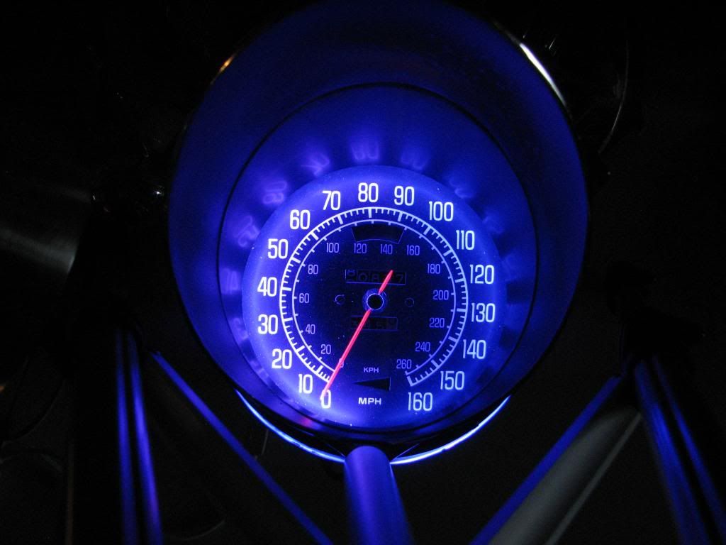
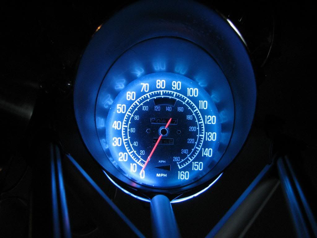
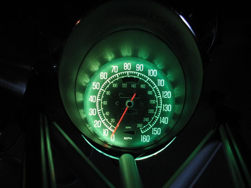
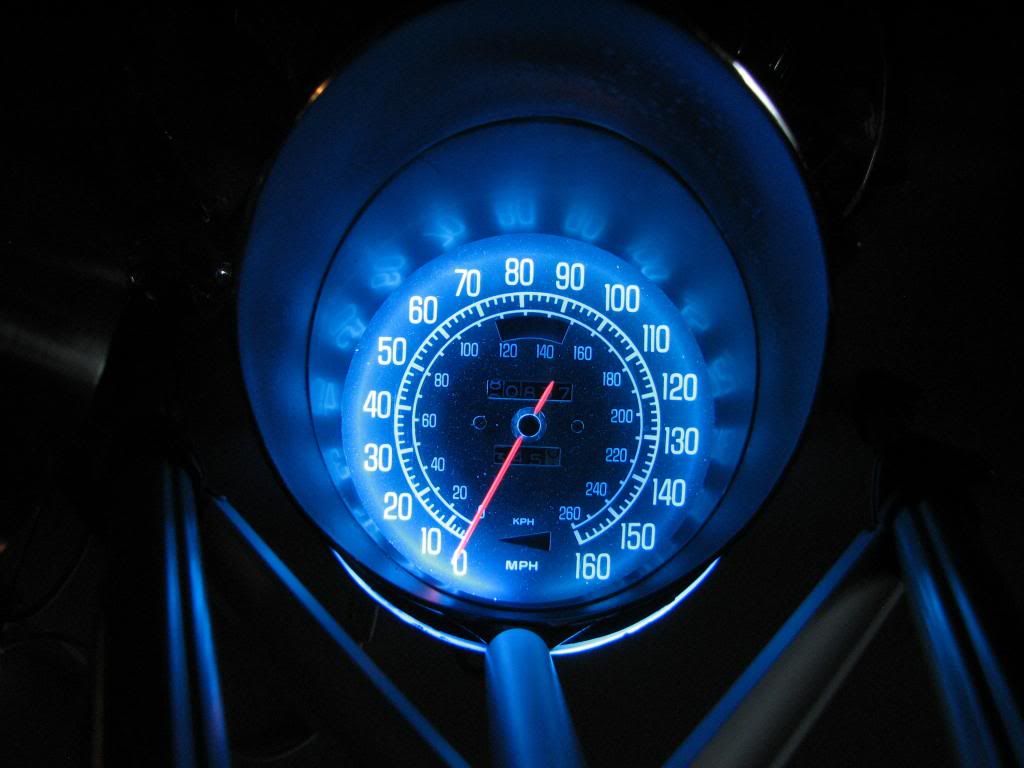
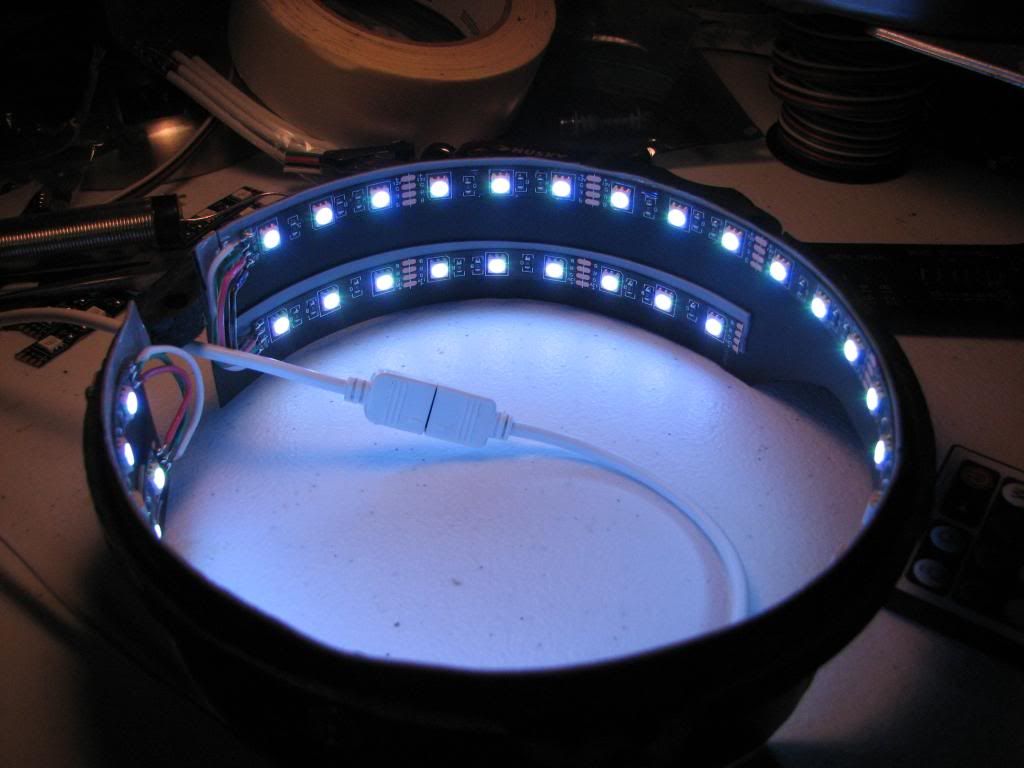
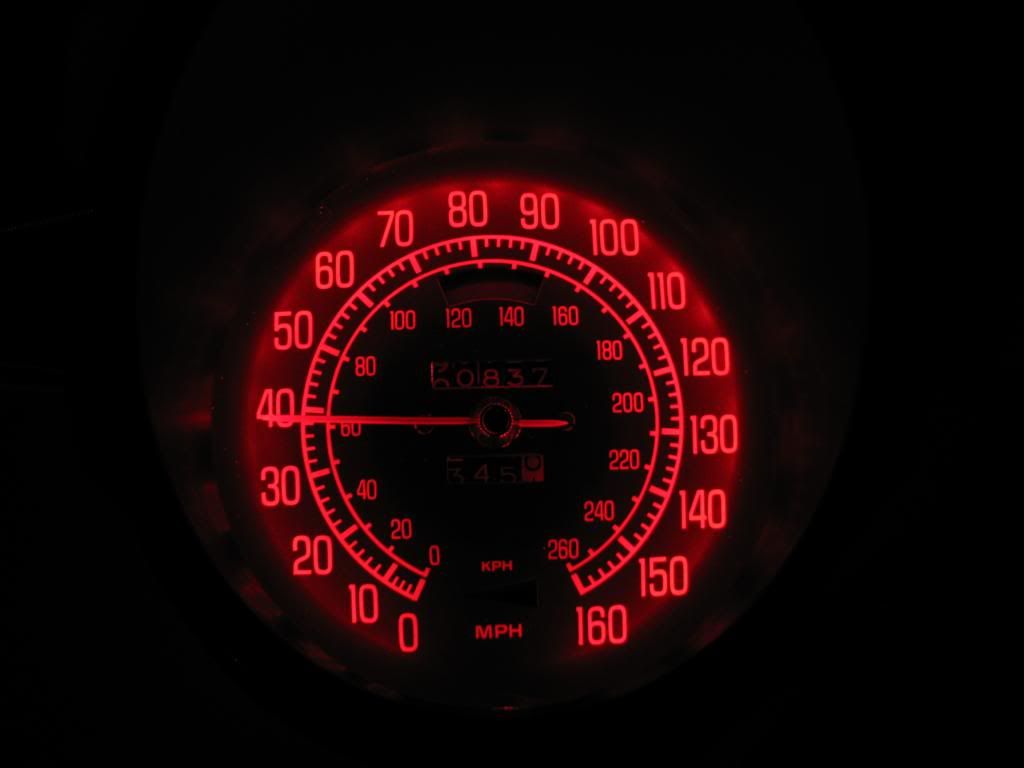
And the final result:
White:
Blue:
Green:
Red:
So what do you think? I give myself probably a D+ for my casting piece and some might laugh at my amateur piece, but I think for the budget I did ok for my first time out. Ideally I'd have access to a aluminum fabricator machine to make it out of a solid piece of metal, or I'd really love to try one of those fancy new 3D printing machines, that would truly be cool.
I've made some progress on the 5 gauge center cluster as well, just haven't finished it yet for photos or publishing, but hopefully in the next month or so.

I decided to go with my wood ring concept and fabricate some kind of housing. The goal was to allow the most light to reach the surface of the gauge as well as require little to no modifition of the housings. I think I'm pretty close.
So I started off at Michaels craft store of all places picking up some wooden rings that I think they use for crochet.
and then using some hardening modeling clay, create the flange supports:
Once I had all of that ready, I decided I'd try my hand at making a mold. Now since I was doing this on a shoestring budget, I didn't get to use silicone for my mold, instead I used a product called Composimold that you can reuse over and over just by reheating it and making a new mold, plus the fact that I could get 40oz for about $36, silicone is a lot pricier for a one time use and the first time out. Then I needed some plastic and decided to go with black Aluminilite Casting Resin which by itself wasn't cheap at around $65:
I also bought some mold release:
So here's my wood and clay prototype ready for molding:
I then proceeded to make a molding structure to pour the Composimold into:
I then had to let it cool. As you can see I didn't hot glue the inside at all and ended up with a few leaks:
I then took apart the mold structure and removed my wood/clay prototype from the mold.
Next up I mixed up the plastic resin according to the instructions and poured into my mold:
It only takes a couple minutes for the plastic resin to cure after which I can then remove my casting. Here it is with casting flash that needs to be trimmed.
Now back one second to my comment about using Composimold vs silicone, the quality of the casting was rather poor and I ended up with a lot of bubbles in my casting. However, I didn't buy the correct "bubble buster" that you're supposed to use with Composimold so that most likely had a negative effect.
So I took the part to my sander/grinder and tried to clean it up a bit:
At this point I'm ready to make my LED strip that will be mounted inside my newly cast piece:
I added some plastic surround to the inside of the cast piece to allow more room for the top housing to fit into the groove as well as hide the outside of the can that's now possible to see since I've raised up the entire top part of the housing. This plastic surround was just fashioned out of a cheap plastic binder I bought at Walmart for like $1.
Even though I thought my double-sided tape would work well, I decided to use some pop rivets to secure it in place:
Test fitting the piece, obviously not perfect:
Now I just had to mount the LED strip I soldered together using more double-sided tape. I may use some sort of epoxy glue later on.
Now you may ask, why the two rows of LEDs? The reason is that the top row is to luminate the surface of the gauge, but the bottom row will help illuminate the odometer and trip wheels. Overkill? Maybe, but I wanted to do this as correctly as I could.
Putting it all together:
And the final result:
White:
Blue:
Green:
Red:
So what do you think? I give myself probably a D+ for my casting piece and some might laugh at my amateur piece, but I think for the budget I did ok for my first time out. Ideally I'd have access to a aluminum fabricator machine to make it out of a solid piece of metal, or I'd really love to try one of those fancy new 3D printing machines, that would truly be cool.
I've made some progress on the 5 gauge center cluster as well, just haven't finished it yet for photos or publishing, but hopefully in the next month or so.
Last edited by StingrayLust; 04-29-2014 at 02:54 AM.
04-29-2014, 03:29 AM
#17


Baby Jesus...StingrayLust !!!!
fantastic posting..thank you soooooo much.... great info for us all!!!
fantastic posting..thank you soooooo much.... great info for us all!!!
04-29-2014, 09:26 AM
#18
I would love to do this next time I open up my dash, I can't wait to see how the center cluster comes out!

