
secondary Fuse Block
 01-08-2014, 04:28 PM
#1
Racer

Thread Starter
Member Since: May 2009
Location: LA CA
Posts: 269
Likes: 0
Received 0 Likes
on
0 Posts
http://i63.photobucket.com/albums/h1...lueSea13-1.jpg
Do any of You guys uses this to power headlights, fans or accessories. I am thinking of it but I am wondering if necessary or if the clean install is worth.
Just trying to get ideas
Do any of You guys uses this to power headlights, fans or accessories. I am thinking of it but I am wondering if necessary or if the clean install is worth.
Just trying to get ideas
 01-08-2014, 04:50 PM
#2
Melting Slicks

Member Since: Jul 2001
Location: Massapequa Park NY
Posts: 2,608
Likes: 0
Received 10 Likes
on
8 Posts

I added a Painless wiring 7 circuit auxiliary fuse block to power up the electric headlight operators, electric fans, headlights, amp, etc.
Mounted it on a panel attached to the inner fender where the vacuum tank would normally be located.
Jim
Mounted it on a panel attached to the inner fender where the vacuum tank would normally be located.
Jim
The following users liked this post:
Dagious (07-09-2022)
01-08-2014, 05:17 PM
#3
Racer
Thread Starter
Member Since: May 2009
Location: LA CA
Posts: 269
Likes: 0
Received 0 Likes
on
0 Posts
How is it working for You.. Any issues
01-09-2014, 08:28 AM
#4
Melting Slicks
Member Since: Jul 2001
Location: Massapequa Park NY
Posts: 2,608
Likes: 0
Received 10 Likes
on
8 Posts
Only one problem for me, I used the spare ignition terminal in the fuse block to trigger the relay. One late summer cruise I knocked it off with my foot some how which killed the electric fans & started to overheat. Jumped on the parkway And was able to cool it down enough to stop & figure out what was wrong  Made for a little excitement.
  Now there are a couple of zip ties added.
I also added a 100 amp alternator, junction block that's used on later Vettes, and up-sized some wiring due to the higher loads.
A few pics I have
The mounting plate with the block & relays attached
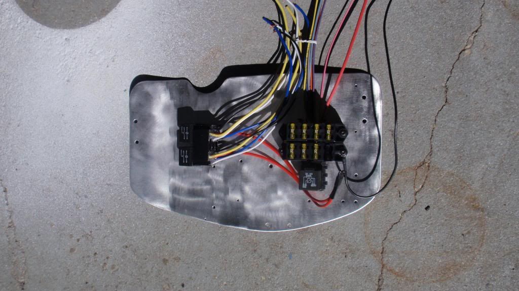
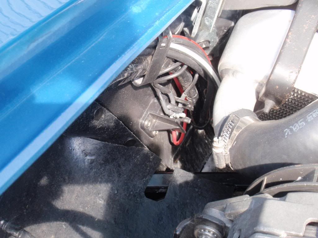
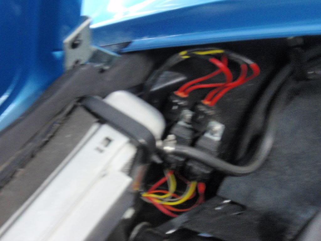
Junction block on D/S inner fender near alternator
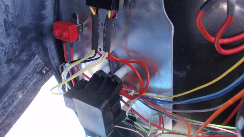
Fuse block etc on D/S inner fender where vaccum tank would normally be
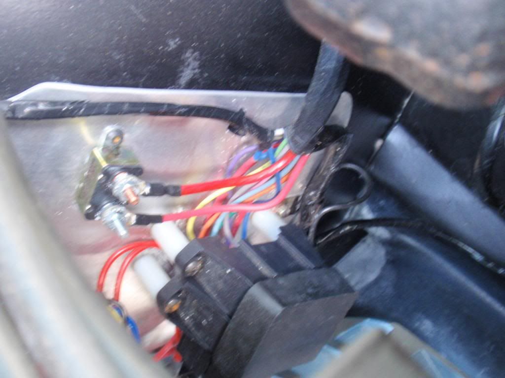
Fan relays & fuses on P/S inner fender
Jim
Made for a little excitement. Now there are a couple of zip ties added.I also added a 100 amp alternator, junction block that's used on later Vettes, and up-sized some wiring due to the higher loads.
A few pics I have
The mounting plate with the block & relays attached

Junction block on D/S inner fender near alternator

Fuse block etc on D/S inner fender where vaccum tank would normally be


Fan relays & fuses on P/S inner fender

Jim
01-09-2014, 08:37 AM
#5
Nam Labrat


Member Since: Sep 2013
Location: New Orleans Loo-z-anna
Posts: 33,945
Received 4,207 Likes
on
2,759 Posts

I've "run out" of spare terminals on my OEM fuse block by installing cooling fans/etc. on my '68 project.
For safety's sake.....I'll follow the lead of other members----add another heavy-gage 12V cable from the starter + lug to a new aux. fuse block since I just upgraded to a 130 amp alternator/larger feed & charging wires (the original wires were getting a "little warm").
For safety's sake.....I'll follow the lead of other members----add another heavy-gage 12V cable from the starter + lug to a new aux. fuse block since I just upgraded to a 130 amp alternator/larger feed & charging wires (the original wires were getting a "little warm").
01-09-2014, 10:09 AM
#6
Le Mans Master

When I added my 2 fans I ran those fused wires directly to the starter lug also. For my electric headlight conversion, it draws power from 1 wire to the alternator. No problems.
01-09-2014, 08:56 PM
#7
Racer
Thread Starter
Member Since: May 2009
Location: LA CA
Posts: 269
Likes: 0
Received 0 Likes
on
0 Posts
Only one problem for me, I used the spare ignition terminal in the fuse block to trigger the relay. One late summer cruise I knocked it off with my foot some how which killed the electric fans & started to overheat. Jumped on the parkway And was able to cool it down enough to stop & figure out what was wrong Made for a little excitement. Now there are a couple of zip ties added.
I also added a 100 amp alternator, junction block that's used on later Vettes, and up-sized some wiring due to the higher loads.
A few pics I have
The mounting plate with the block & relays attached
Junction block on D/S inner fender near alternator
Fuse block etc on D/S inner fender where vaccum tank would normally be
Fan relays & fuses on P/S inner fender
Jim
Made for a little excitement. Now there are a couple of zip ties added.I also added a 100 amp alternator, junction block that's used on later Vettes, and up-sized some wiring due to the higher loads.
A few pics I have
The mounting plate with the block & relays attached
Junction block on D/S inner fender near alternator
Fuse block etc on D/S inner fender where vaccum tank would normally be
Fan relays & fuses on P/S inner fender
Jim
01-10-2014, 09:26 AM
#8
Melting Slicks
Member Since: Jul 2001
Location: Massapequa Park NY
Posts: 2,608
Likes: 0
Received 10 Likes
on
8 Posts
http://www.summitracing.com/parts/prf-70207/overview/
Included the circuit breaker that you see. Plan out everything in advance & make sure you have enough circuits. I took the feed for the new panel from the horn relay terminal and the trigger for the isolation relay from the ignition terminal on the main fuse block.
Many ways to accomplish the same end result. I just chose this way.
Jim
01-14-2014, 11:56 AM
#10
Melting Slicks
Member Since: Jul 2001
Location: Massapequa Park NY
Posts: 2,608
Likes: 0
Received 10 Likes
on
8 Posts
Only the control circuit side of the fan relays is fed from the aux panel.
The headlight relays are wired so that the control circuit is the from the main fuse panel and the load side of the relay is from the aux fuse panel. Don't remember what the current draw is, but its easy to calculate if you measure the resistance of the headlight bulbs
Jim
01-19-2014, 09:51 PM
#11
Racer
Thread Starter
Member Since: May 2009
Location: LA CA
Posts: 269
Likes: 0
Received 0 Likes
on
0 Posts
IIRC the relay & circuit breaker are rated at 30 amp. The load side feed for the fan relay (high current) comes off of the junction block next to the radiator with a separate fuse located at the relay on the P/S fender.
Only the control circuit side of the fan relays is fed from the aux panel.
The headlight relays are wired so that the control circuit is the from the main fuse panel and the load side of the relay is from the aux fuse panel. Don't remember what the current draw is, but its easy to calculate if you measure the resistance of the headlight bulbs
Jim