When you click on links to various merchants on this site and make a purchase, this can result in this site earning a commission. Affiliate programs and affiliations include, but are not limited to, the eBay Partner Network.
Trailing Arm, strut rod, half-shaft Installation - one method - long post
Again, in case someone ever searches
There are lots of threads on installing the trailing arms, strut rods, 1/2 shafts here's what worked for me.
Used a set of locking forceps to navigate the bolt into location and then held in just inside the pocket with them
Piece of cardboard folded down into the drain area of the pocket to attempt to not destroy the paint
Jackstand set to the same height as the bottom of the pocket less two notches and a thick chunk of foam (paint thing again)
Set the T/A into the pocket and rest it on the stand (it doesn't balance well, you need to hold onto it)
Anyway, by having the stand just slightly low, the arm will pivot on the front of the pocket and you can lift the back of the arm a little to align the bolt.
Keep the arm pulled to the outside of the pocket so the bolt can be slid in another 1/2" or so with the forceps and them use the forceps to start it into the arm. Once started, I just move the forceps as far back on the bolt as possible and slide the arm over to them, that puts the bolt almost 1/2 through the bushing.
Move the forceps or a screwdriver to the back of the bolt and push it in, wiggle/pivot the arm to align the outside hole and pop it through
(first one took 20 minutes, second side maybe 5 minutes)
Spin the nut on just to hold everything and since I'm using new arms, I just evenly shimmed both sides for now
Put a 3/4" block of wood under the arm to hold it in sort of the right spot
I installed the strut rod (poly bushings) into the T/A first. Lube everything with poly grease, slathered the metal sleeve with anti-sieze and used an dead-blow hammer and an alignment bar to get the sleeve lined up.
I files a chamfer on the end of the shock mount where the flat meets the end (the thread had a chamfer but the flat didn't)
and put the new shock mount in about 3/4 of the way. I couldn't get it all the way through since it wasn't lined up on the "D" side of the bracket. (the chamfer wasn't enough to help pull it straight)
I put a larger (3/16"+) chamfer all the way around the end on the old mount. using the old mount in from the "D" side, let the large chamfer guide it into the sleeve to straighten out the strut rod. Pull it out and then push the mount in all the way.
On the strut rods I'm using, They were resisting going up into location on the center bracket so I extended them about an inch on both ends so that they reached into the center mounting bracket past where they needed to be and into the area where it widens out
Needed to lift the T/A about 2" more at the rear to help the alignment, slather everything again and a couple of taps with the deadblow and it went in no problems
Shorten the strut rod and a few taps and it comes over into the proper location, installed the bolt, locating washers etc
Once the bolt was in, lengthen the strut rods again allows for the 1/2 shaft to go in place, shorten them to hold in in while you put the various bolts, locks etc
Thin walled 5/8 sparkplug socket seems to be the only thing that I own that fits well
I ran the e-brake lines etc next (mine are re-located)
then the shocks (top first, then the bottom seemed to work best. anti-seize on the top, white grease on the bottom)
Watch the cone washer direction on the bottom
Once the shock are in you can remove the wooden block and check the torque on everything
Oh, I removed the spring heat-shield hanging there after running my arm across the edge of it too many times. Do that first next time
Almost like a car again, I still need to finish torquing everything and bend the french locks, spring, swaybar, lots of smaller details still to attend to but this feels like progress
Anyway, I'm sure there's easier ways but this worked for me, I'll probably notice something I missed and have to take half of it back off.
Mooser
Last edited by Mooser; 11-21-2017 at 09:12 PM.
Reason: fix photobucket mess
Nice write up and nice job as well. I'm almost readyto start back with the install of my whole rear assy but have a few more items to finish detailing first.
Nice write up moser that is just about word for word how I did mine! It feels great knowing that great minds think alike an *fingers crossed* I must've done it right!! Your car looks great keep the pictures coming
What keeps the bolt from moving around in that slot? Just torquing them really, really tight?
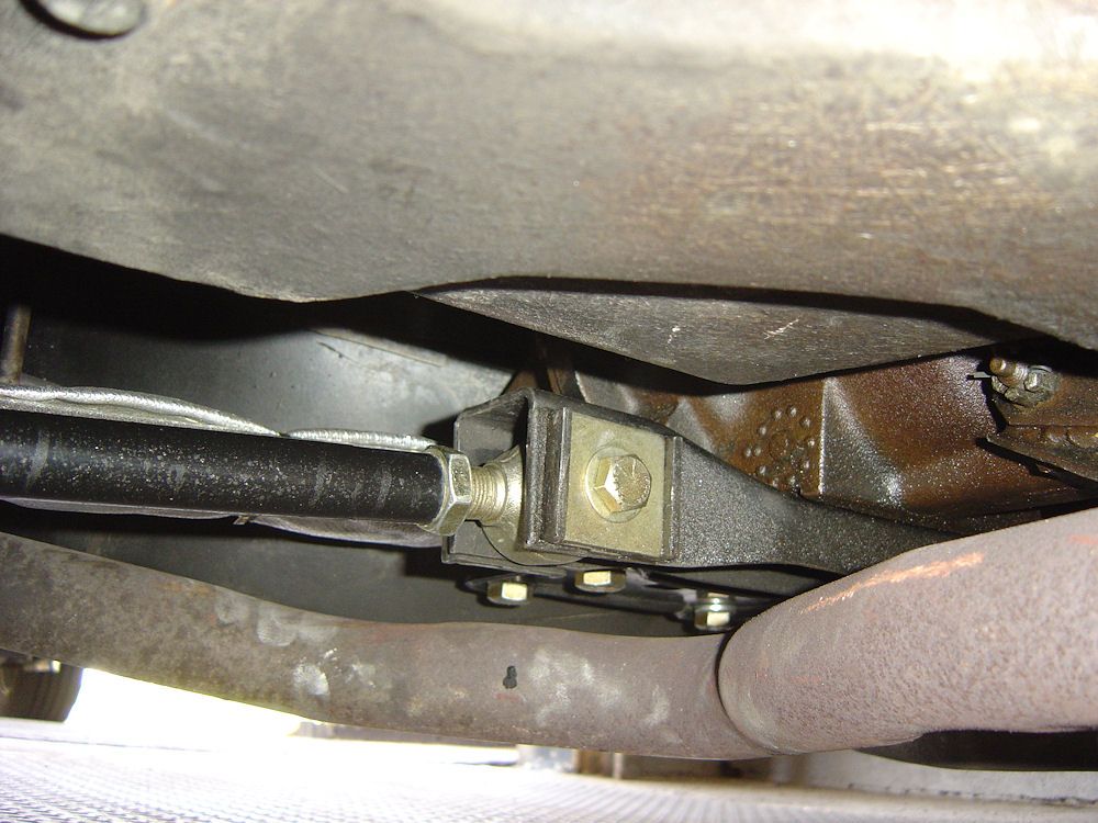
There is a steel plate on both sides that just fits in-between the two "lips" (I had to machine it down to actually fit, it was too big by almost .080") and only has a hole in the center.
If you look close on the next picture you can kind of see one of the plates
Mooser
Um mine did not have a steel plate but a odd oversized washer that was ovaled to keep it in place is this wrong?!?
I will get a pic put up tonight
Sounds like the stock setup. The length of the rod is fixed and you adjust the camber by rotating that washer, thereby moving the pivot point in or out in that slot.
These arms (aftermarket) use a fixed pivot point and tie-rod type ends that change the length of the arm to adjust the camber
If you search the forums you'll find lots of "discussions" as to how each affects suspension geometry and which is better and why whatever the other guys is using is the worst thing ever.
GM stuck with the eccentric washer system for a lot of years so it certainly couldn�t have been too bad. For my purposes, this setup should work well, if not I�ve got all the pieces to change it back to stock
Mooser
There is a steel plate on both sides that just fits in-between the two "lips" (I had to machine it down to actually fit, it was too big by almost .080") and only has a hole in the center.
If you look close on the next picture you can kind of see one of the plates
Mooser
Mine are a little different but the same principle. The plates centre the bolts.
here is what i have instead of the little metal plate that you guys have i asked the corvette mechanic at J&D and then showed the picture to a mechanic at west coast corvettes and he said that mine are correct as well he said most have the plate some have the oval on both sides weird
Yeah, that's the stock style setup. Mine was the same critter
When they adjust the camber, rotating those washers causes the bolt to slide in the slot and moves the pivot point for the arm. Not sure how long they used it, far as I know from 63 right up to 82 used more or less the same setup.
Mooser
sweet i was just worried that it was another bubba fixture on the car. when i saw the set up you guys have i got scared lol. i guess that set up is for the adjustable torque arms. how much of a difference do you guys notice with the adjsutable arms? are they worth the extra money?
sweet i was just worried that it was another bubba fixture on the car. when i saw the set up you guys have i got scared lol. i guess that set up is for the adjustable torque arms. how much of a difference do you guys notice with the adjsutable arms? are they worth the extra money?
Once the camber is set correctly there is no difference. And the price is about the same. Just a matter of preference. I thought that I would try the new. I can go back if need be.
Im bringing this great old thread back to life! Im about to install new offset trailing arms and just wanted to know if you apply any grease inside into the bushing sleeve to eliminate some bolt on sleeve friction??? How about around and in between the shims?
Im bringing this great old thread back to life! Im about to install new offset trailing arms and just wanted to know if you apply any grease inside into the bushing sleeve to eliminate some bolt on sleeve friction??? How about around and in between the shims?
Thanks
Personally, I smeared a bunch of anti-seize between, around, under and beside all the new stainless shims (shouldn't matter and they are pinned in place so shouldn't really move around)
Used a good slathering of a waterproof grease (rubber compatible) on/in the bushing and facing washers.
More anti-seize on the threads for the nut.
To each their own. This will allow for anything to come apart if it ever needs to and does provide some lubrication if it's actually needed.
Mooser

 04-11-2012, 10:12 PM


 . They got a little dirty on the drive home from the storage facility.


