
My '76 restoration (long post)
 10-10-2013, 10:30 AM
#361
Drifting


Thread Starter
Member Since: Aug 2010
Location: Kanuckistan
Posts: 1,617
Received 127 Likes
on
68 Posts
2022 C3 of the Year Finalist - Modified

You betcha, it's been almost 4 years.
It's actually a good think I didn't realize at first how long it would be, you have to be a little stupid/stubborn to get yourself into such project.
Seing section getting done is a nice motivational kick, provided I really need it.
 10-10-2013, 10:32 AM
#362
Drifting
Thread Starter
Member Since: Aug 2010
Location: Kanuckistan
Posts: 1,617
Received 127 Likes
on
68 Posts
2022 C3 of the Year Finalist - Modified
My install will be a little trickier since I want to install the driver side without rail, just to get the maximum headroom.
10-10-2013, 10:39 AM
#363


 10-10-2013, 10:42 AM
#364
Melting Slicks


 you're a full 12" taller than I so I can see where you would! I do think that without having to put the Corvette rails on it would save you a little bit of headroom, not much but a little.
My idea is to use flat steel maybe 3/16" thick by 3" wide by whatever length they need to be to go from front to back bolt holes on both fiero seat tracks and floorboard seat holes, it may need to be a bit wider than 3" but I haven't measured anything so I don't know that.
11-11-2013, 11:09 PM
#366
Drifting
Thread Starter
Member Since: Aug 2010
Location: Kanuckistan
Posts: 1,617
Received 127 Likes
on
68 Posts
2022 C3 of the Year Finalist - Modified
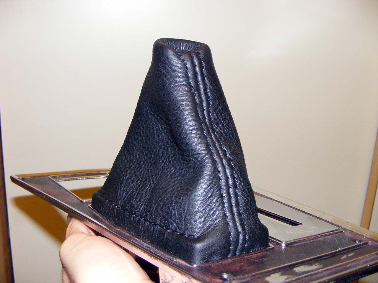
Today is leather day.
I pulled off the piece of Moose I skin I have in stock and decided to make a shifter boot.
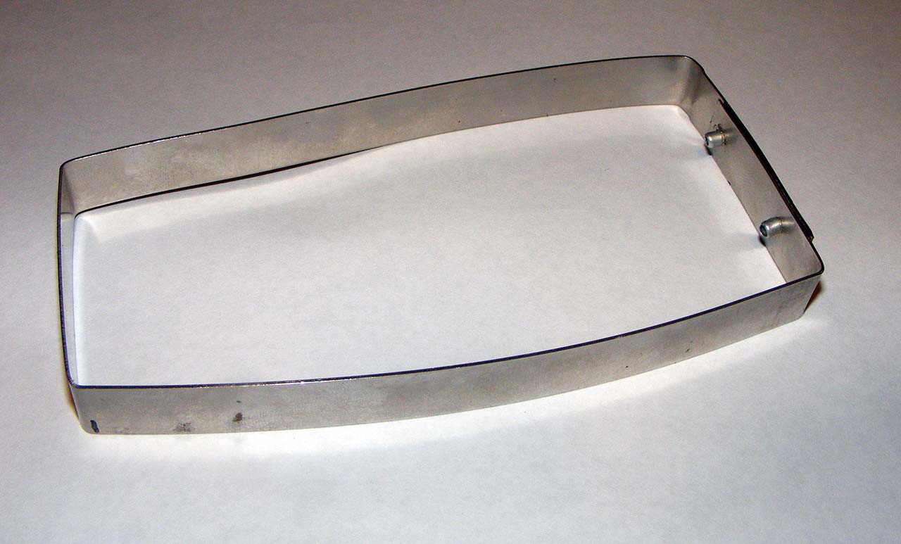
First, I used a very long hose clamp to make a brace that match the shifter hole shape (minus the thickness of the leather)
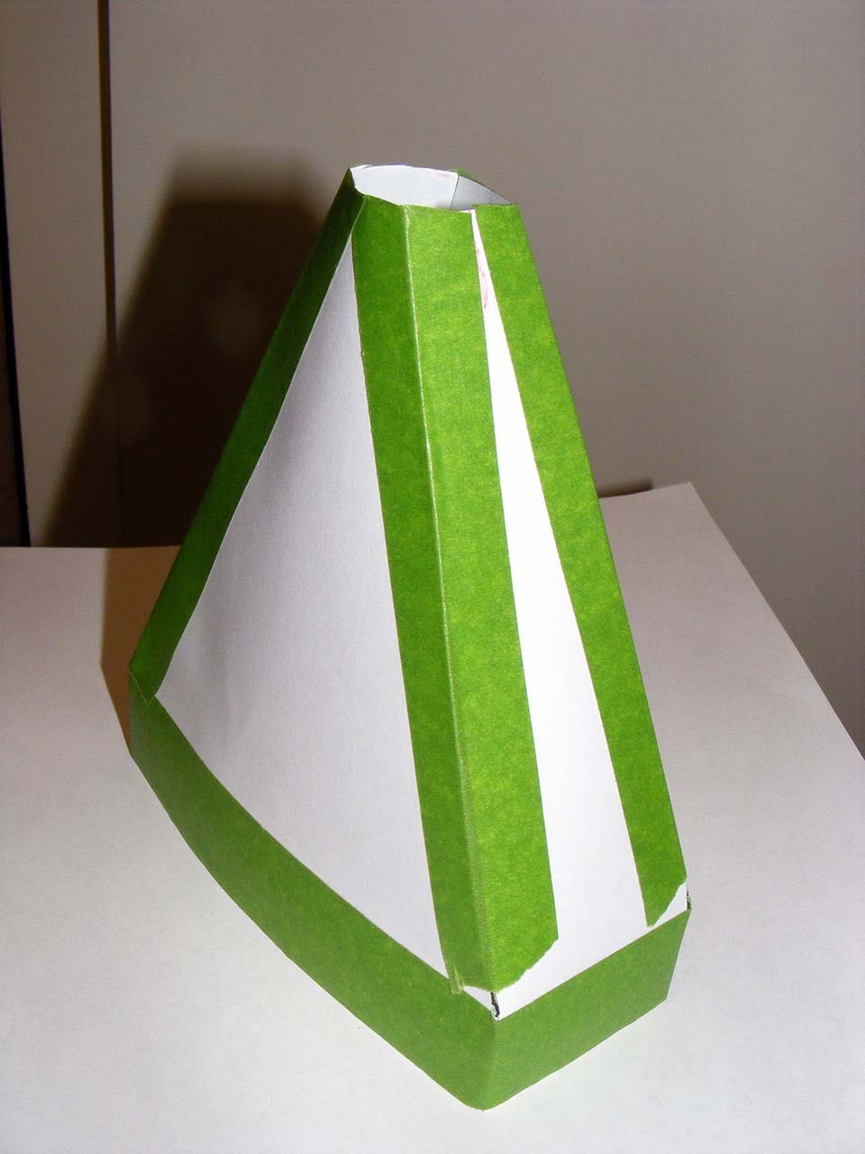
Then made a paper model
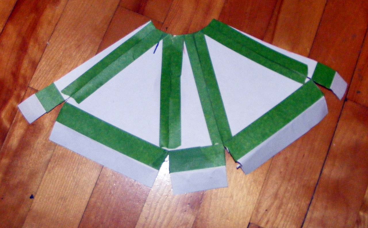
I cut the model when I want the stich to be :
Then it's time to cut the leather.
I went for a full flat felled seam as stitch, no less
Here the fitting stage :
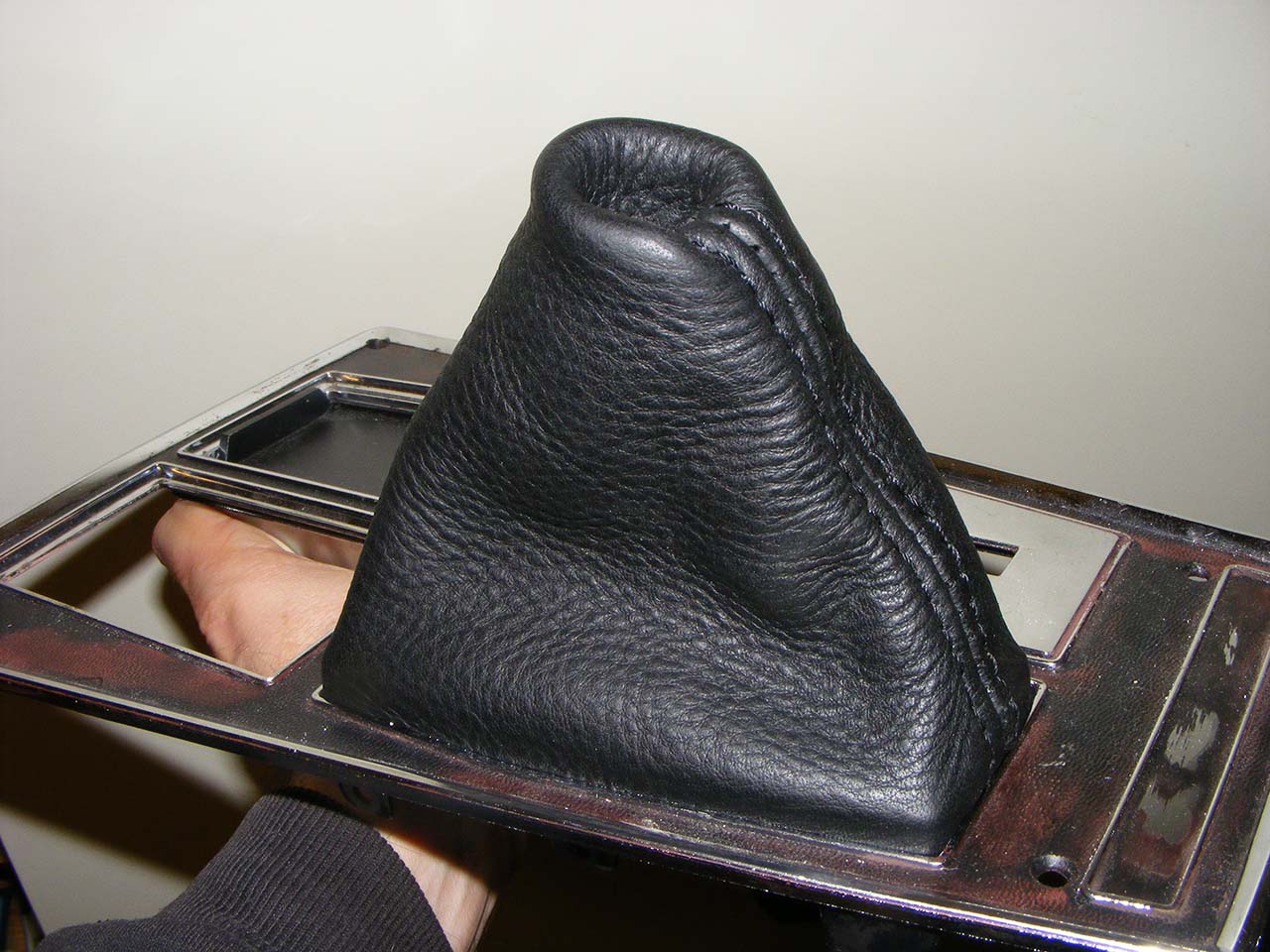
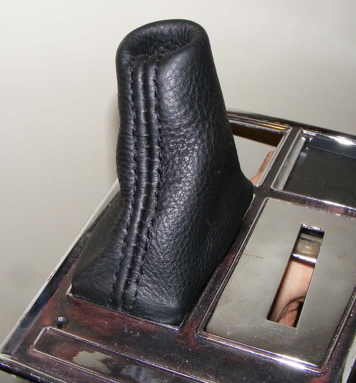
Here's when I got the brace sewed in :
I bought an awesome tool for hand sewing leather, it's call the "speedy stitcher", all was sewed in couple of hours, without numb finger nor the usual cursing.
Here's a video of how it work (pretty much like sewing machines)
I still need to complete the cutting of the hole in the shifter plate, so the brace could go all the way down.
Also to be added is a metal ring (sewed in too) to shape the top of the boot, that will come as a fine tuning once I get everything together.
I pulled off the piece of Moose I skin I have in stock and decided to make a shifter boot.
First, I used a very long hose clamp to make a brace that match the shifter hole shape (minus the thickness of the leather)
Then made a paper model
I cut the model when I want the stich to be :
Then it's time to cut the leather.
I went for a full flat felled seam as stitch, no less
Here the fitting stage :
Here's when I got the brace sewed in :
I bought an awesome tool for hand sewing leather, it's call the "speedy stitcher", all was sewed in couple of hours, without numb finger nor the usual cursing.
Here's a video of how it work (pretty much like sewing machines)
I still need to complete the cutting of the hole in the shifter plate, so the brace could go all the way down.
Also to be added is a metal ring (sewed in too) to shape the top of the boot, that will come as a fine tuning once I get everything together.
Last edited by Denpo; 08-18-2017 at 09:44 PM.
The following users liked this post:
lickahotskillet (06-22-2023)

 11-12-2013, 09:31 AM
#370
Drifting
Thread Starter
Member Since: Aug 2010
Location: Kanuckistan
Posts: 1,617
Received 127 Likes
on
68 Posts
2022 C3 of the Year Finalist - Modified
Thanks!
U serious?
What I can do is scan the model and put it online.
At user's own risk of course, no guarantee if will fit your setup.
Dash light are led. Led strips around the inside of driver gauges and led bubbles everywhere else.
Thanks for watching.
U serious?
What I can do is scan the model and put it online.
At user's own risk of course, no guarantee if will fit your setup.
Dash light are led. Led strips around the inside of driver gauges and led bubbles everywhere else.
Thanks for watching.
11-16-2013, 06:46 PM
#371
Drifting
Thread Starter
Member Since: Aug 2010
Location: Kanuckistan
Posts: 1,617
Received 127 Likes
on
68 Posts
2022 C3 of the Year Finalist - Modified
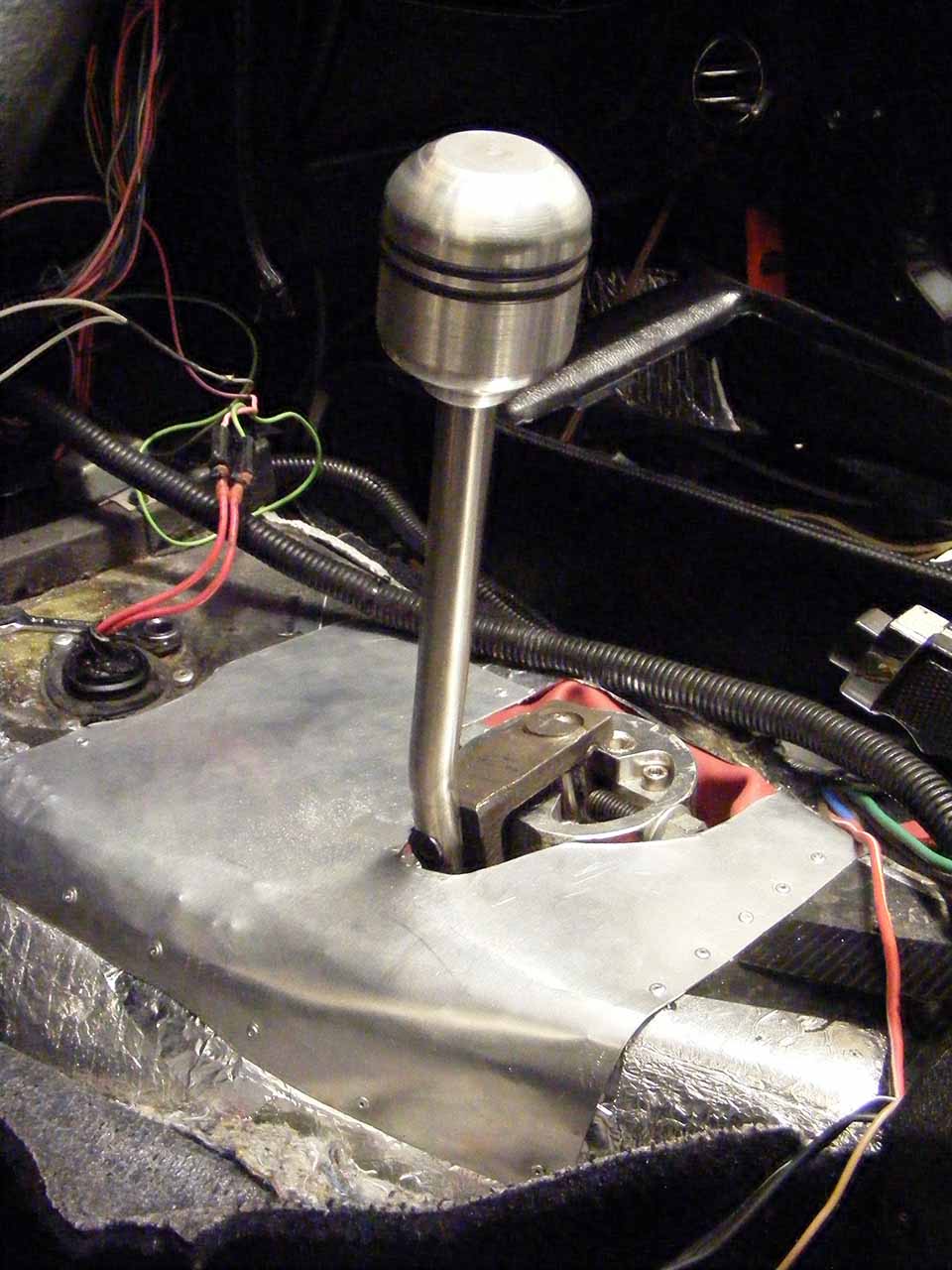
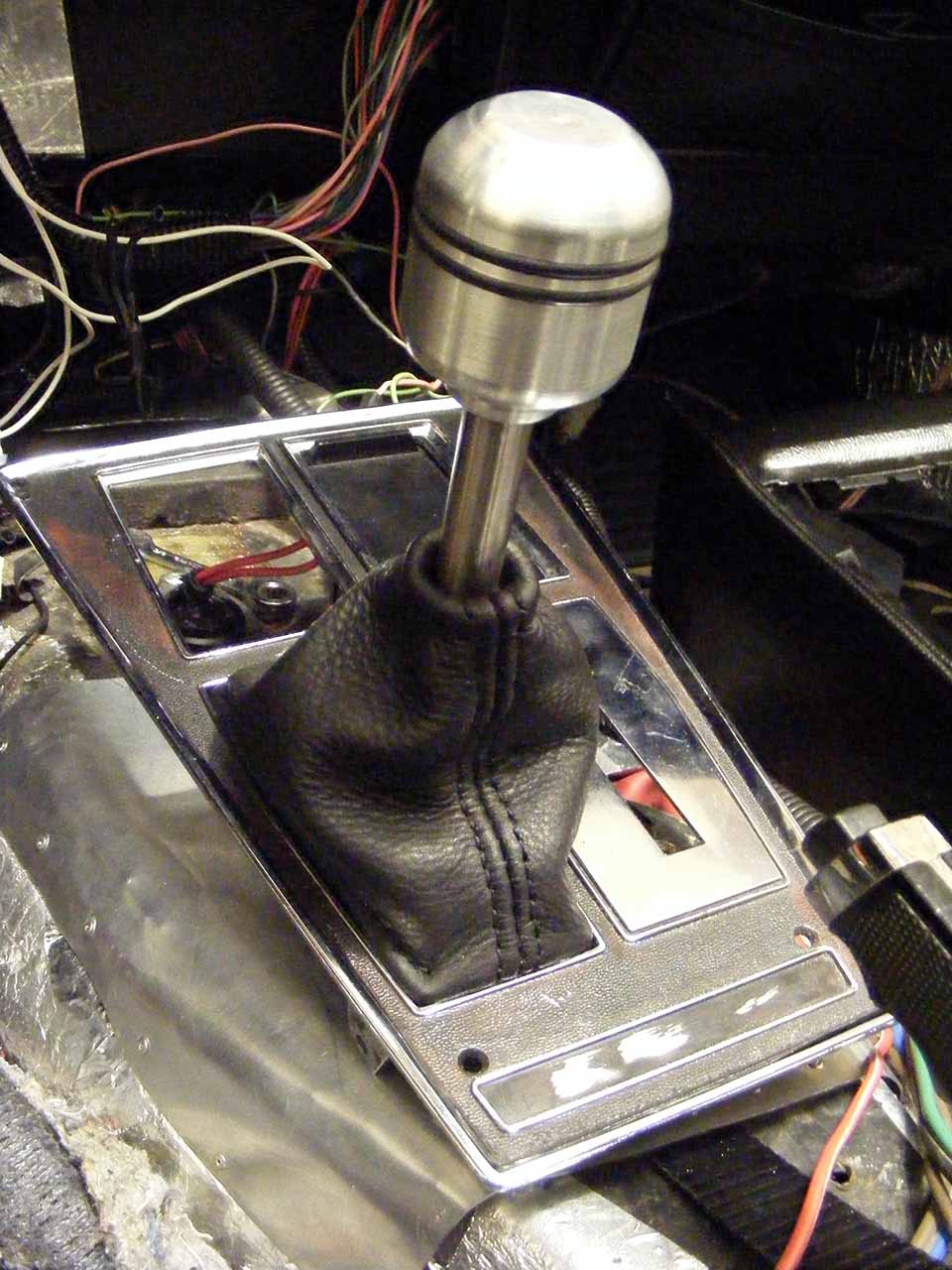
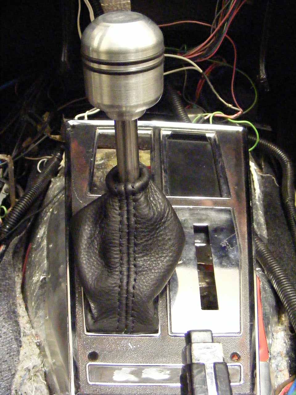
Shifter area done!
I tried a couple of shifter *****, but none would feel right. Too small for my big hand, so I had one machined.
The two grooves are fitted with o-rings to give some grip.
Not sure I'll polished it, I like the raw machined look.
I tried a couple of shifter *****, but none would feel right. Too small for my big hand, so I had one machined.
The two grooves are fitted with o-rings to give some grip.
Not sure I'll polished it, I like the raw machined look.
Last edited by Denpo; 08-18-2017 at 09:46 PM.
11-27-2013, 10:10 PM
#372
Drifting
Thread Starter
Member Since: Aug 2010
Location: Kanuckistan
Posts: 1,617
Received 127 Likes
on
68 Posts
2022 C3 of the Year Finalist - Modified
I'm stuck on a serious eletrical nonsense, the kind of bug that force you to put back down everything *once again*.
So In between my head scratching/hair pulling sessions, I'm finding little details that needed attention.
Door switches : I had three pairs of switches in pityfull shape. I tored them all apart and managed to rebuilt two good one. It's all about removing the plastic piece at the back without breaking it more than it is already.
Not shown on pic : I added some epoxy glue to the crack on the single connector switch.
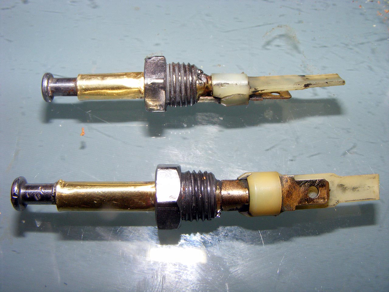
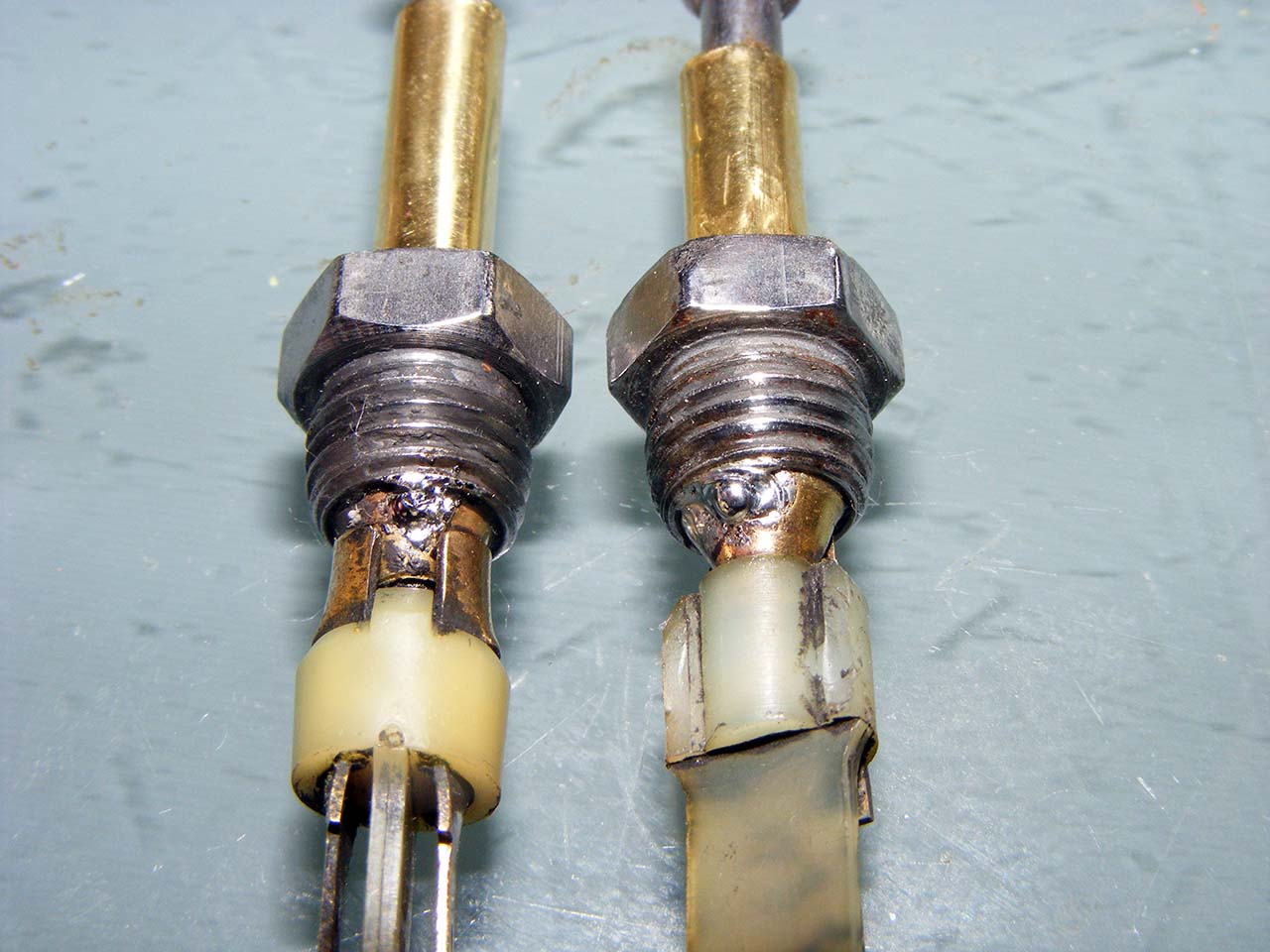
Believe it or not, the nut and the yellow metal tube would not make electrical contact. I could polish the tube, but couldn't access the inner of the tube.
I ended putting a bead of solder.
Now I could hear the infamous sound of the key buzzer (probably haven't run for decades...). I'm wondering if anyone ever looked for replacement, a more gentle ding sound.
Another thing that was bugging me is my replacement led light bulbs.
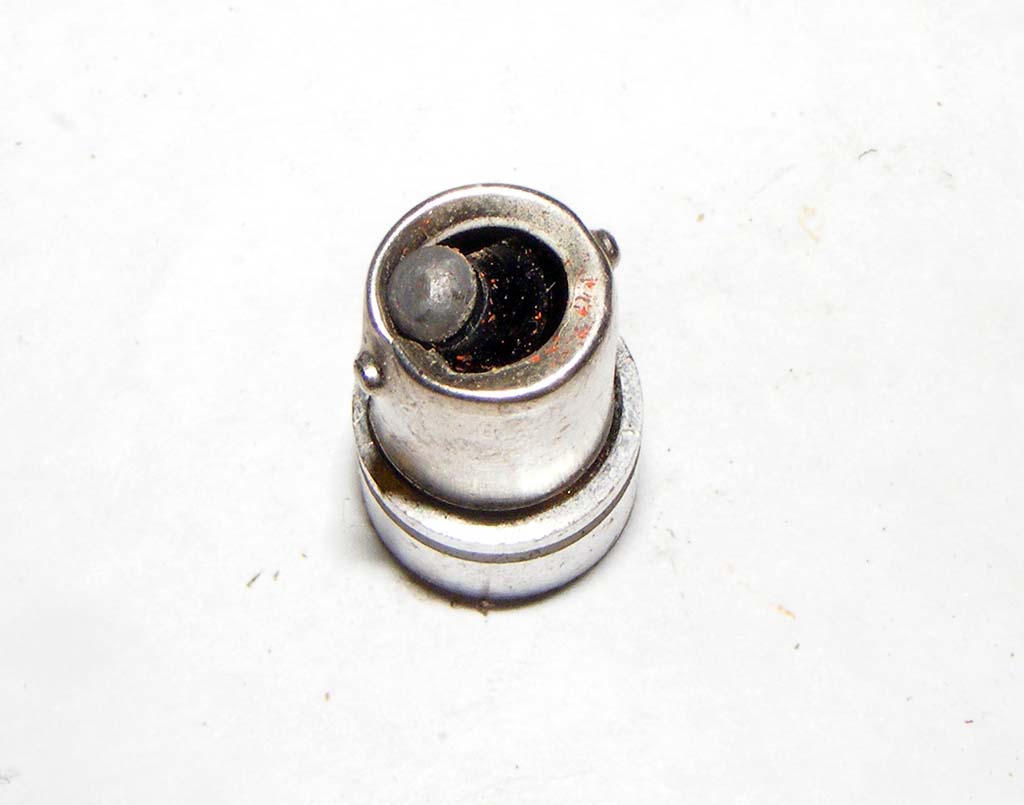
They light great, but the way the base is made is really *ahem*.
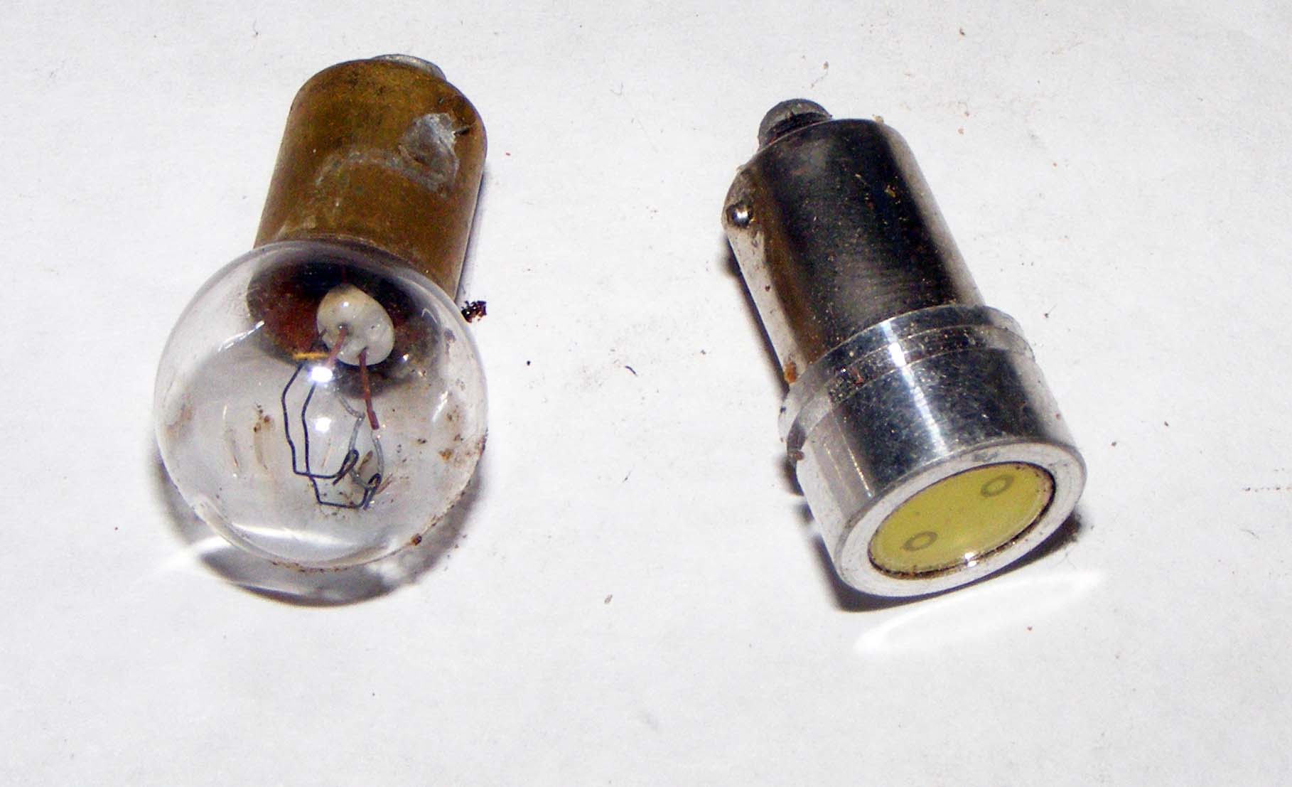
See how vaguely the tab are formed.
The tabs are to short to begin with, and at the first constraint they collapse in. They was not holding in the socket as well as the old one. With all the vibrations.... last thing I wanna do it go hunting a lightbulb that felt in my speedo.
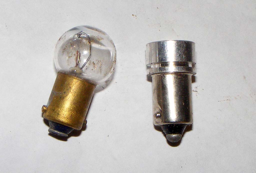
So I decided to make the one out of the best of both.
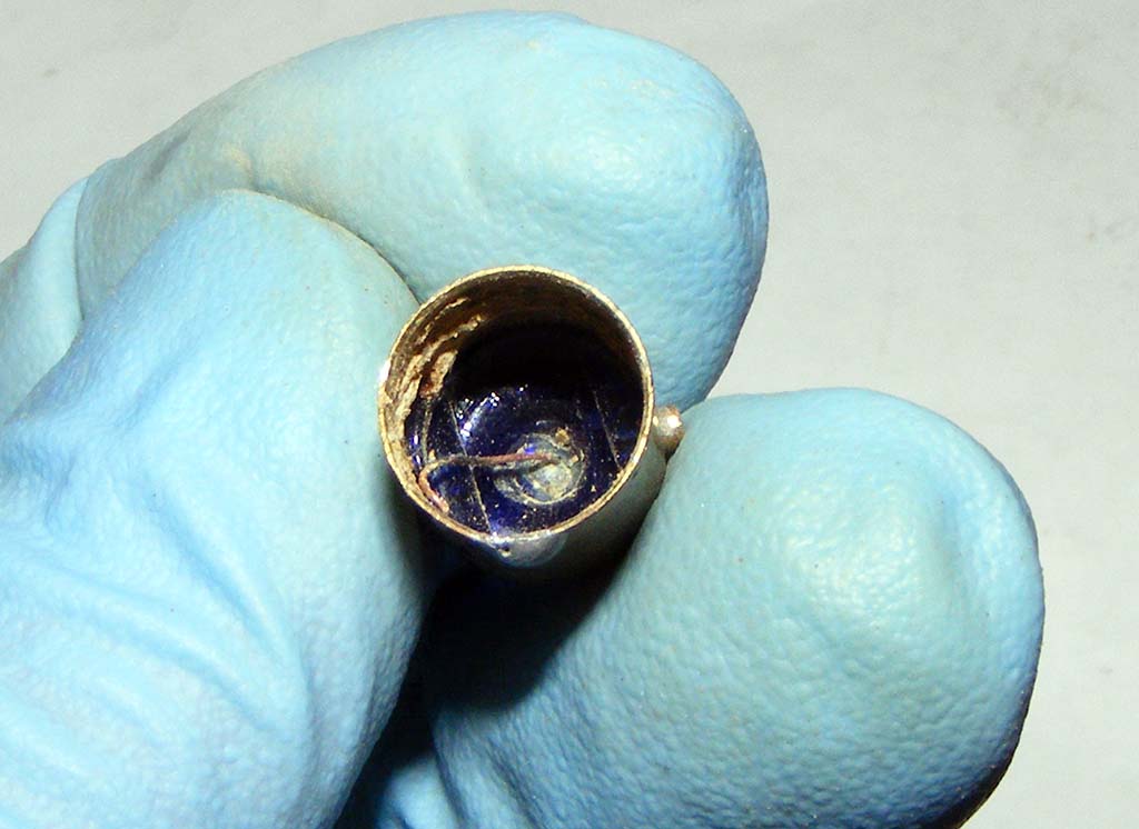
I Gutted out the old bulbs, made sure not to touch the black ceramic base.
I dismantled the LED bulb.
They are easy to pry open, it's help by just a dab of something like hot glue.
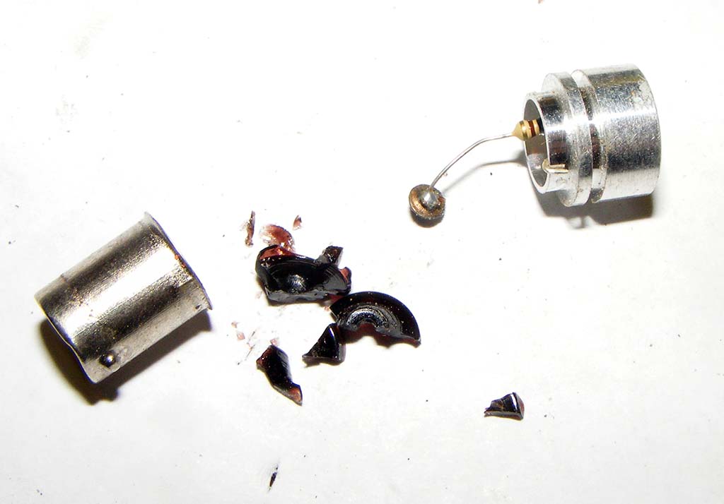
To be frank I didn't know the base of lightbulb was made of some kind of solder.
With a solder pump I removed the old bulb lamp tip until I got a hole. At that point the filament inside has fallen.
Then reinserted the old base one the LED head. They are much tighter than before.
I soldered the tips, et voila! (ok, still need to cut the filament and file the tup...)
Now, it you excuse me, 'got hairs to pull.
So In between my head scratching/hair pulling sessions, I'm finding little details that needed attention.
Door switches : I had three pairs of switches in pityfull shape. I tored them all apart and managed to rebuilt two good one. It's all about removing the plastic piece at the back without breaking it more than it is already.
Not shown on pic : I added some epoxy glue to the crack on the single connector switch.
Believe it or not, the nut and the yellow metal tube would not make electrical contact. I could polish the tube, but couldn't access the inner of the tube.
I ended putting a bead of solder.
Now I could hear the infamous sound of the key buzzer (probably haven't run for decades...). I'm wondering if anyone ever looked for replacement, a more gentle ding sound.
Another thing that was bugging me is my replacement led light bulbs.
They light great, but the way the base is made is really *ahem*.
See how vaguely the tab are formed.
The tabs are to short to begin with, and at the first constraint they collapse in. They was not holding in the socket as well as the old one. With all the vibrations.... last thing I wanna do it go hunting a lightbulb that felt in my speedo.
So I decided to make the one out of the best of both.
I Gutted out the old bulbs, made sure not to touch the black ceramic base.
I dismantled the LED bulb.
They are easy to pry open, it's help by just a dab of something like hot glue.
To be frank I didn't know the base of lightbulb was made of some kind of solder.
With a solder pump I removed the old bulb lamp tip until I got a hole. At that point the filament inside has fallen.
Then reinserted the old base one the LED head. They are much tighter than before.
I soldered the tips, et voila! (ok, still need to cut the filament and file the tup...)
Now, it you excuse me, 'got hairs to pull.
Last edited by Denpo; 08-18-2017 at 09:51 PM.
 11-28-2013, 11:00 AM
#374
Nam Labrat


Member Since: Sep 2013
Location: New Orleans Loo-z-anna
Posts: 33,899
Received 4,179 Likes
on
2,739 Posts
AAAAAAAHAAAAAAAA!
Another "Table-of-Contents" Freak.........
We now have enough members (2) to start a cult......errrrr.....club!
This is a great thread/build!
Another "Table-of-Contents" Freak.........
We now have enough members (2) to start a cult......errrrr.....club!
This is a great thread/build!
11-28-2013, 11:27 AM
#375
Drifting
Thread Starter
Member Since: Aug 2010
Location: Kanuckistan
Posts: 1,617
Received 127 Likes
on
68 Posts
2022 C3 of the Year Finalist - Modified
Glad you like the 1st post index, if only I could spend some time refreshing it.

 12-03-2013, 11:06 PM
#378
Drifting
Thread Starter
Member Since: Aug 2010
Location: Kanuckistan
Posts: 1,617
Received 127 Likes
on
68 Posts
2022 C3 of the Year Finalist - Modified
Tonight I made a great step forward. I had my high-side led dimmer prototype working (finally!)
As you may or may not know, LED can't be dimmed with a simple variation of voltage, LED have to be dimmed with a PWM (pulse width modulation), meaning you need to make it flash very fast, so fast it's perceived and continuous light. As you lengthen the gap between each flash, the LEDs look dimmer.
So you need a special device to generate this kind of 'chopped' voltage source.
Problem is, in the electronic world the logical way to cut a circuit, is to do it low side, meaning you hook your led on the positive side of the voltage source, and it's on the way back to the ground that you put your electronic high speed switch.
The obvious problem with the Vette (like also all cars I guess), is that you have no control of the ground. You send the voltage on the plus side, and that's it.
That why you need a high side dimmer, one that cut the circuit between the + source and the led.
And such dimmer are nowhere to be found, it's always easier to wire the LED to be switched on the low side.
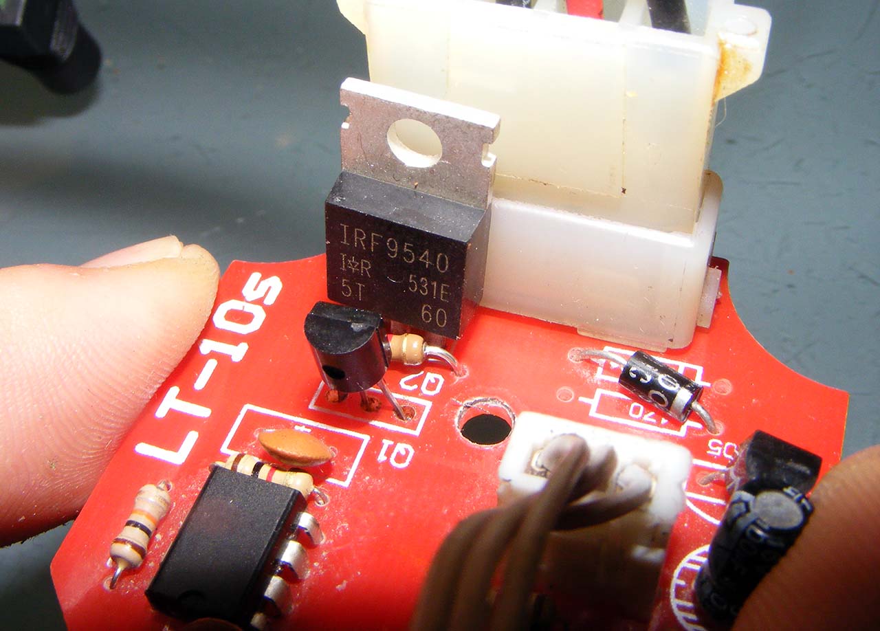
I'm getting better at electronic and I finally managed to hack a regular low side dimmer to function as an high side one.
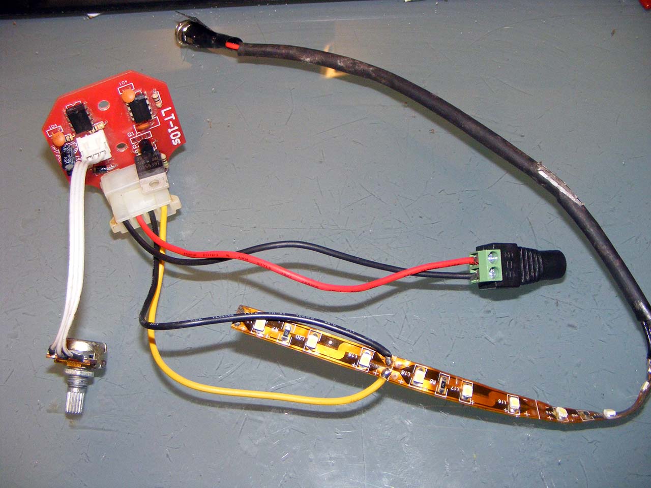
On the top right you can see hacked part of the circuit
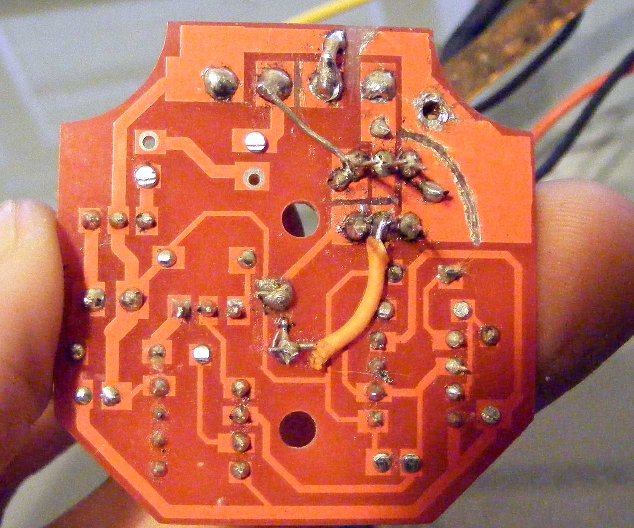
Mind you, this is just a prototype.
Now I can put a module like this at the source of all interior light (the grey wires) and dim them all, without any rewiring.
But that's only the first step....
Now I want to reuse the original variable resistor at the head of the headlight switch to control the dimming level.
It's another story, the resistor varies from 0 to 5 Ohms. That's very low.
An engineer friend gave the direction : feed the "varistor" with a constant current and see how the voltage drop after passing through it.
I will also need and op-amp to amplify the signal to a level that can be sensed by a microcontroller.
I already cut the link on the switch between connector 3 and 4.
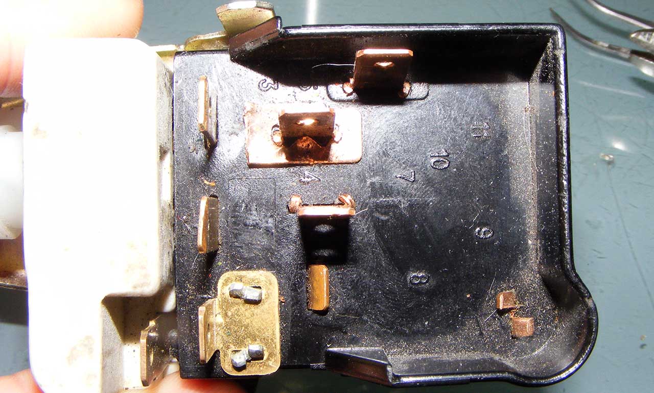
Pin 2 and 3 will connect to a seperate sensing circuit, while what was supposed to connect to pin 2 (the interior light bulb circuit) will be reconnected directly to pin 4, giving the led an unaltered voltage source.
The other good news it that now that I found out my infamous bug and solved the dimming problem, I can reclose everything. I'll just make two wires go from the headlight switch to the central control, I'll put my sensing/dimming device there.
As you may or may not know, LED can't be dimmed with a simple variation of voltage, LED have to be dimmed with a PWM (pulse width modulation), meaning you need to make it flash very fast, so fast it's perceived and continuous light. As you lengthen the gap between each flash, the LEDs look dimmer.
So you need a special device to generate this kind of 'chopped' voltage source.
Problem is, in the electronic world the logical way to cut a circuit, is to do it low side, meaning you hook your led on the positive side of the voltage source, and it's on the way back to the ground that you put your electronic high speed switch.
The obvious problem with the Vette (like also all cars I guess), is that you have no control of the ground. You send the voltage on the plus side, and that's it.
That why you need a high side dimmer, one that cut the circuit between the + source and the led.
And such dimmer are nowhere to be found, it's always easier to wire the LED to be switched on the low side.
I'm getting better at electronic and I finally managed to hack a regular low side dimmer to function as an high side one.
On the top right you can see hacked part of the circuit
Mind you, this is just a prototype.
Now I can put a module like this at the source of all interior light (the grey wires) and dim them all, without any rewiring.
But that's only the first step....
Now I want to reuse the original variable resistor at the head of the headlight switch to control the dimming level.
It's another story, the resistor varies from 0 to 5 Ohms. That's very low.
An engineer friend gave the direction : feed the "varistor" with a constant current and see how the voltage drop after passing through it.
I will also need and op-amp to amplify the signal to a level that can be sensed by a microcontroller.
I already cut the link on the switch between connector 3 and 4.
Pin 2 and 3 will connect to a seperate sensing circuit, while what was supposed to connect to pin 2 (the interior light bulb circuit) will be reconnected directly to pin 4, giving the led an unaltered voltage source.
The other good news it that now that I found out my infamous bug and solved the dimming problem, I can reclose everything. I'll just make two wires go from the headlight switch to the central control, I'll put my sensing/dimming device there.
Last edited by Denpo; 08-18-2017 at 09:53 PM.
12-07-2013, 04:07 AM
#379
Drifting
Thread Starter
Member Since: Aug 2010
Location: Kanuckistan
Posts: 1,617
Received 127 Likes
on
68 Posts
2022 C3 of the Year Finalist - Modified
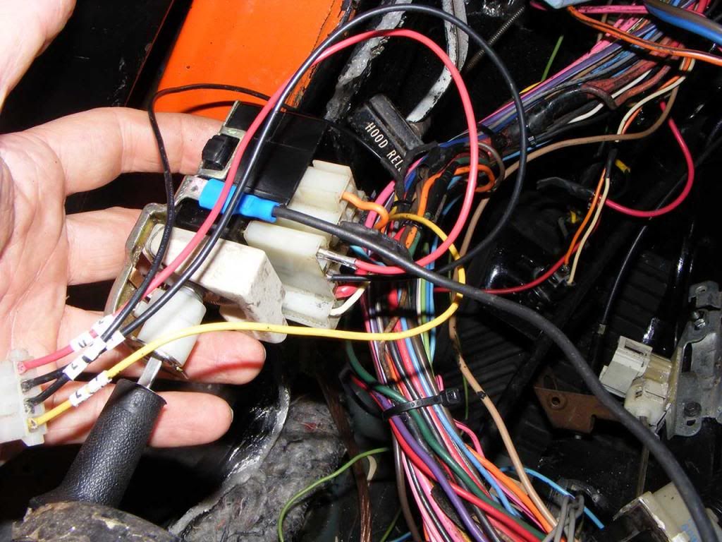
Here is the my led dimming wiring:
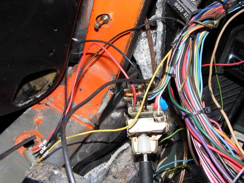
Notice the dark green wire is now directly connected to the pair of brown wire.
It used to be at the place of the black wire.
It's just that now it doesn't go through the resistor.
Of the 4 wires of my own connector :
A pair (red/black) goes to headlight variable resistor, now disconnected from the rest of the switch's circuit.
Of the second pair (yellow/black), yellow goes pick up the grey wire as it leaves the fuse box, as the black is supposed to send it back to the grey circuit.
For the sake of testing I made a dummy device that just closes the circuit. Probably this weekend I will plug in my prototype dimmer, and eventually will install a custom device that will read the resistor to dim accordingly.
Almost forget :
I took me a while to realize I was missing the switch ground strap. Used the tab instead. Wire goes to one of the gauge back plate screw.
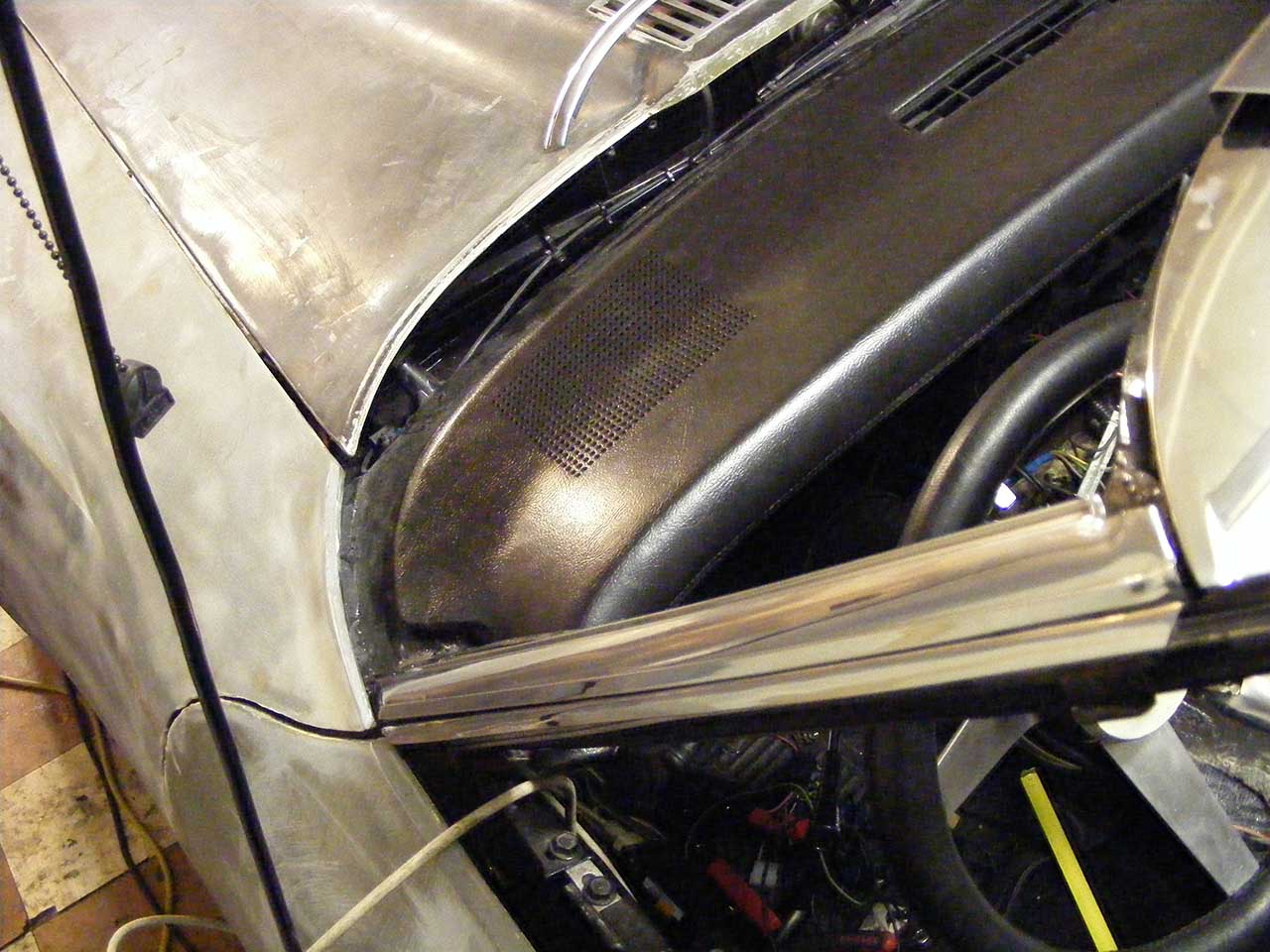
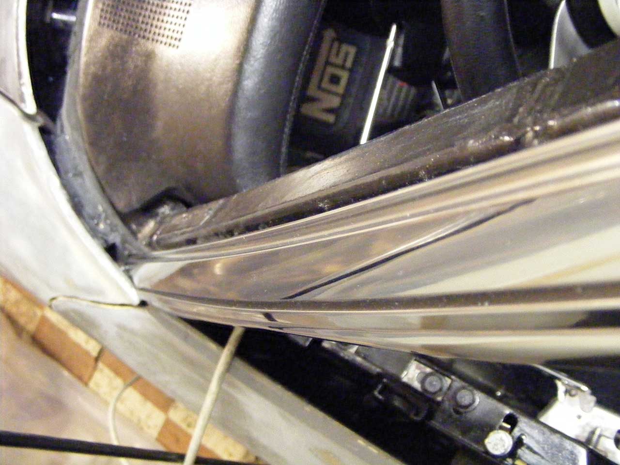
I closed the whole driver dash back in. And now EVERYTHING works.
Flasher, emergency flasher, headlight, hi indicator, brake indicator, key warning buzzer, courtesy lights, switch courtesy bypass, backlight.
Variable resistor probed through my connector report the correct range (0-5ohm).
I'm all good. Finally.
Notice the dark green wire is now directly connected to the pair of brown wire.
It used to be at the place of the black wire.
It's just that now it doesn't go through the resistor.
Of the 4 wires of my own connector :
A pair (red/black) goes to headlight variable resistor, now disconnected from the rest of the switch's circuit.
Of the second pair (yellow/black), yellow goes pick up the grey wire as it leaves the fuse box, as the black is supposed to send it back to the grey circuit.
For the sake of testing I made a dummy device that just closes the circuit. Probably this weekend I will plug in my prototype dimmer, and eventually will install a custom device that will read the resistor to dim accordingly.
Almost forget :
I took me a while to realize I was missing the switch ground strap. Used the tab instead. Wire goes to one of the gauge back plate screw.
I closed the whole driver dash back in. And now EVERYTHING works.
Flasher, emergency flasher, headlight, hi indicator, brake indicator, key warning buzzer, courtesy lights, switch courtesy bypass, backlight.
Variable resistor probed through my connector report the correct range (0-5ohm).
I'm all good. Finally.
12-24-2013, 03:56 AM
#380
Drifting
Thread Starter
Member Since: Aug 2010
Location: Kanuckistan
Posts: 1,617
Received 127 Likes
on
68 Posts
2022 C3 of the Year Finalist - Modified
This gonna be a pretty Xmassy post today.
Santa knows I've been a good boy.
He knows I've spent days polishing my SS trims
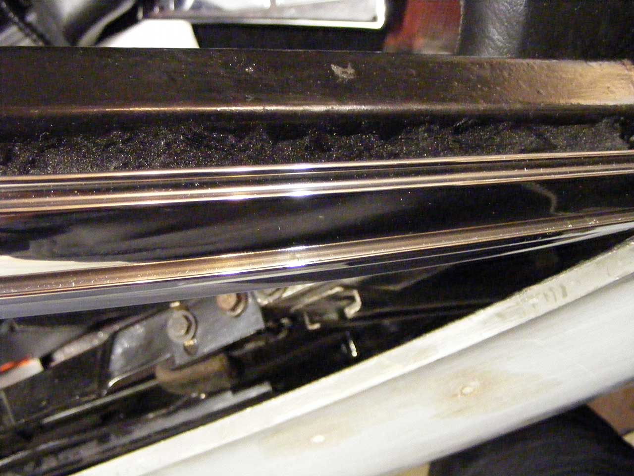
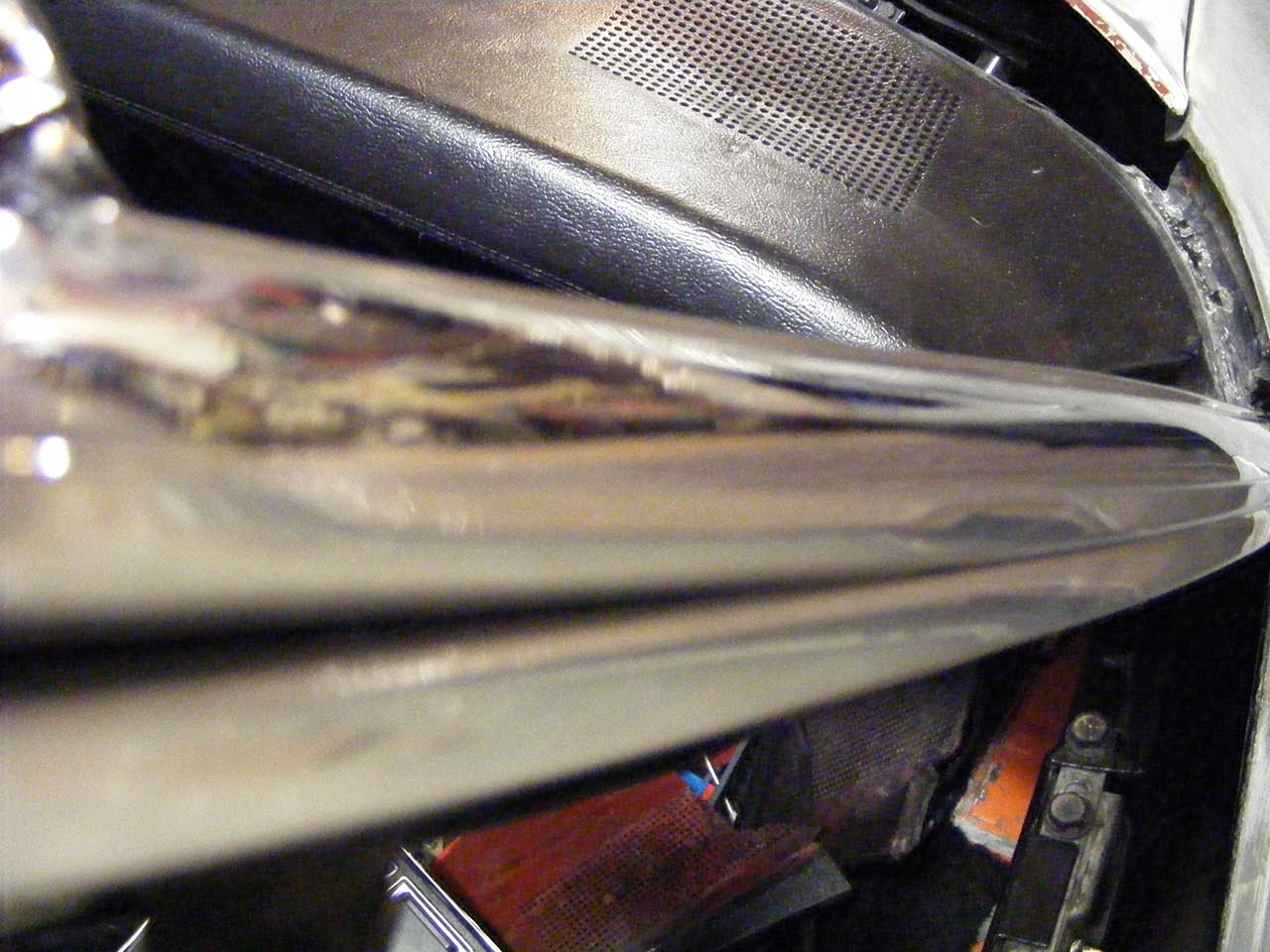
I did 600/800/1000/1200 (all but 600 are wet sanding), polish on hard wheel with black compound then polish on smooth wheel with green compound.
Both polishing have been done in two passes, one hard then one smooth.
Then test-installed the whole setup :
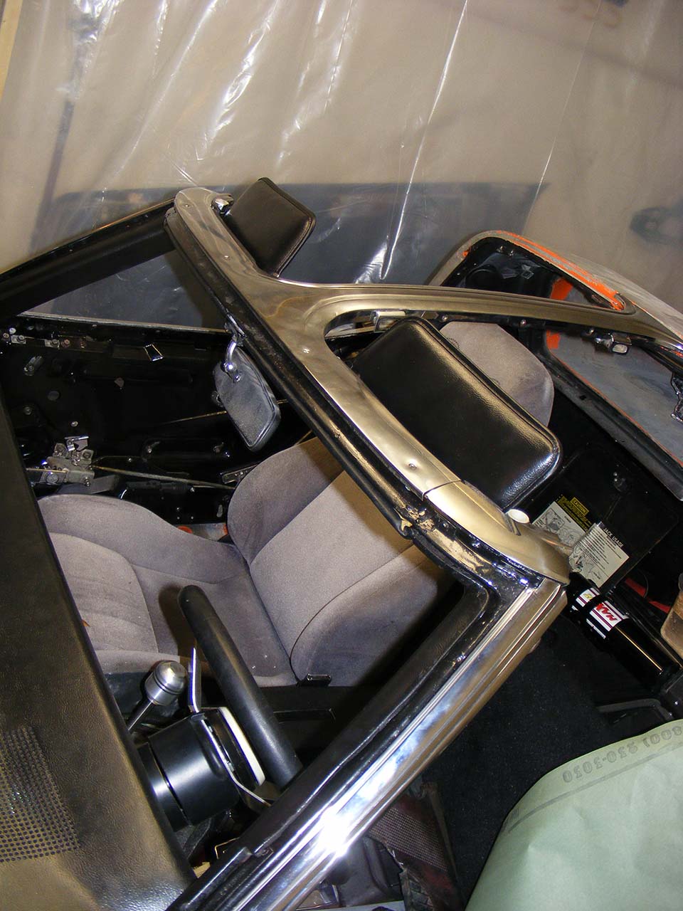
By the way if someone has a close pic of the screws that goes on top of the T trim, that would be cool.
So since I've done my homework, Santa made sure I receive all the cool stuff I ordered.
First is something I've been searching for a while.
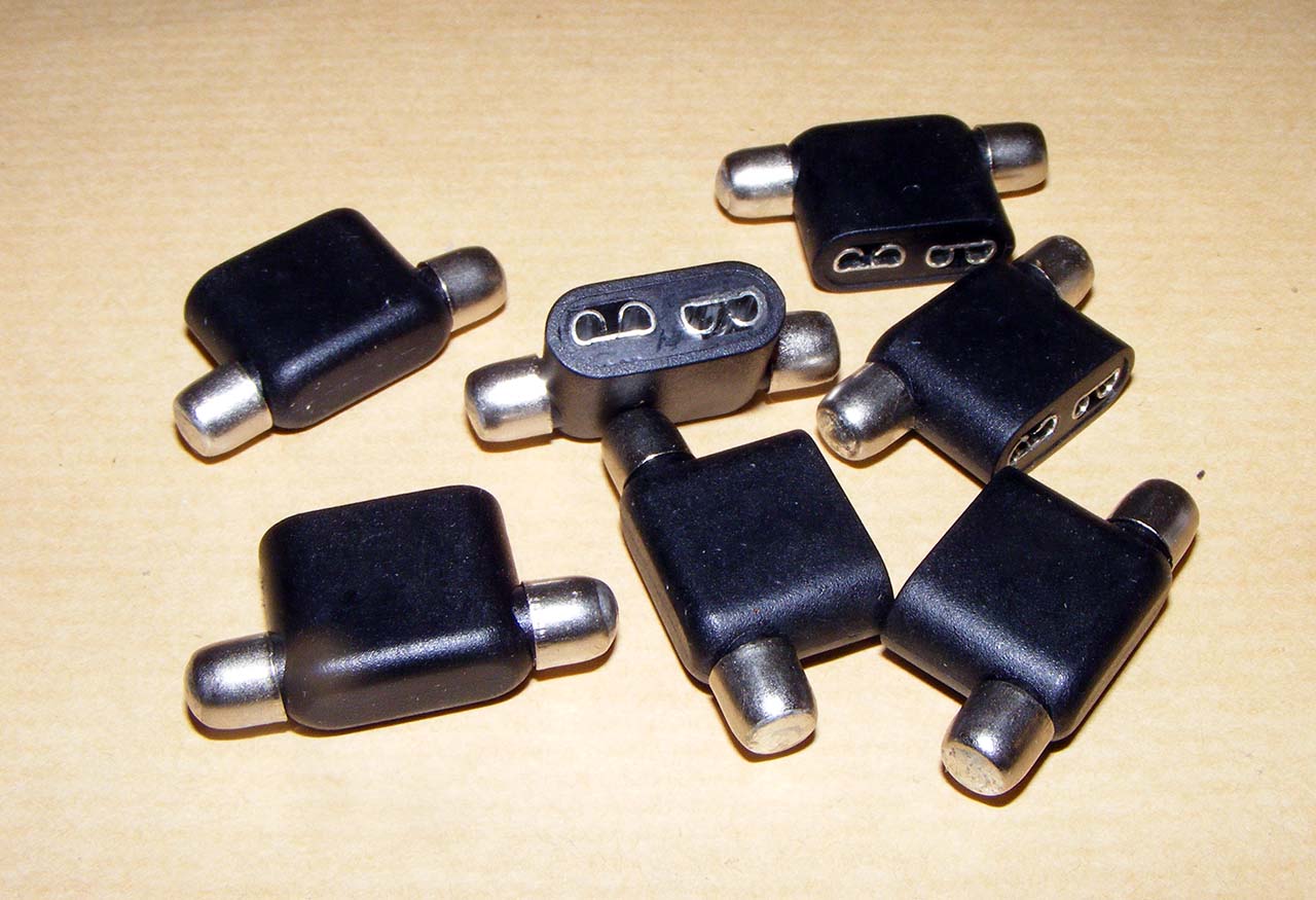
Glass fuse to Blade fuse adapter.
I ordered a pack of 8 and only received 7, I'm sure they will sort this out.
How many time I broke the glass fuse while trying to remove it.
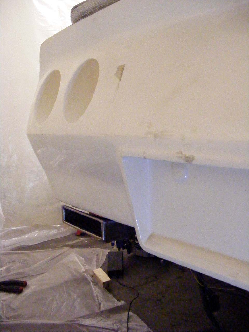
Next gift is a pair of DRL/Flasher combo.
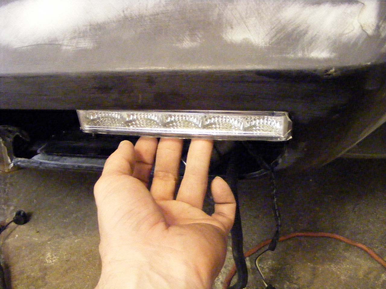
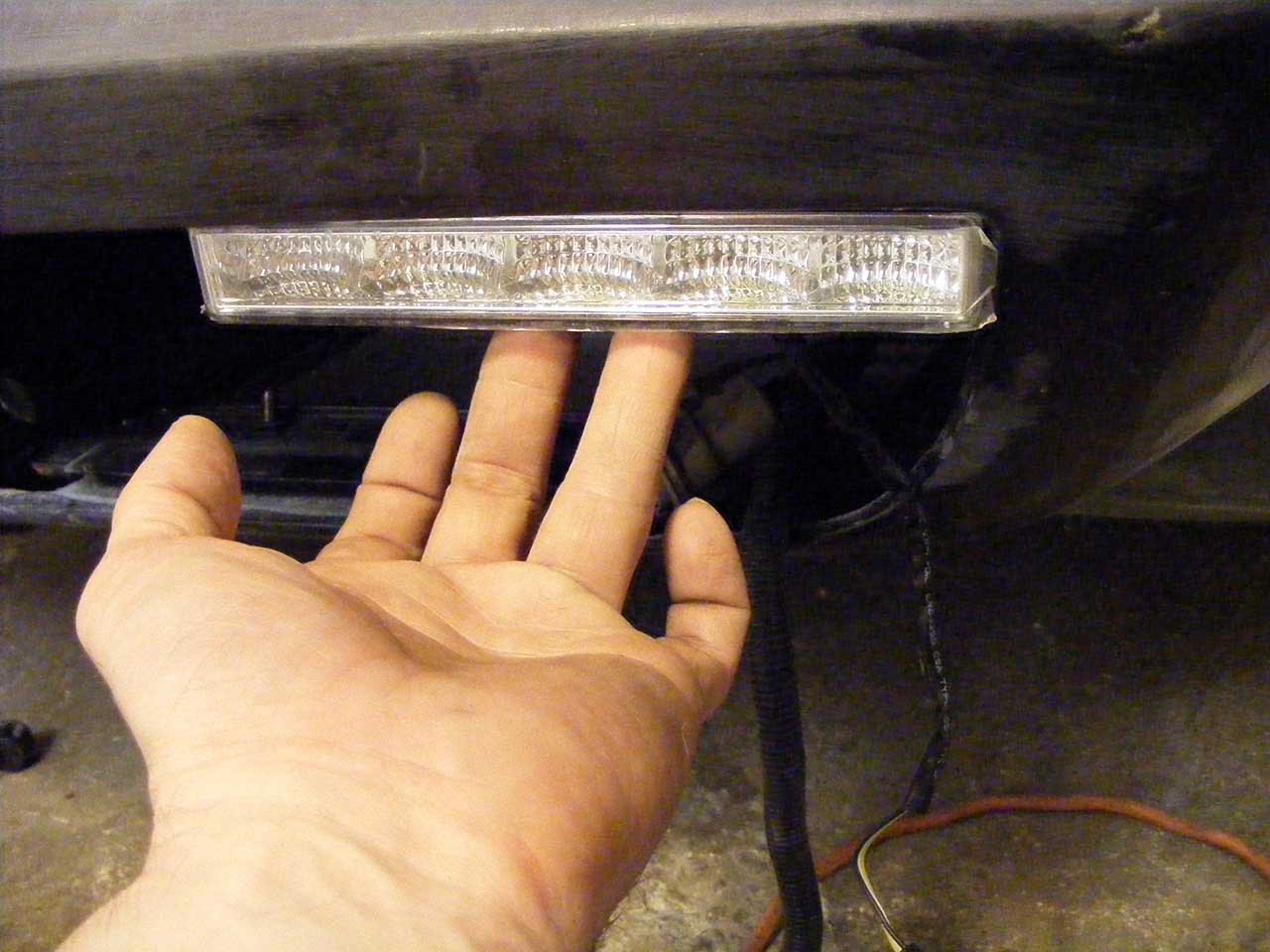
I'm kind of torn. If I was listening to the crazy in my, I'd cut the bumper and put them in, same position as picture, just higher.
That would be cool, but those unit are not designed to work at such a steep angle. They are bevel shaped, just not enough.
With those mounted flush to the bumper, the light would be spread outward.
How bad would it be? well, I think I need to make some real life tests to find out.
Last gift, is a pair of exhaust tips.
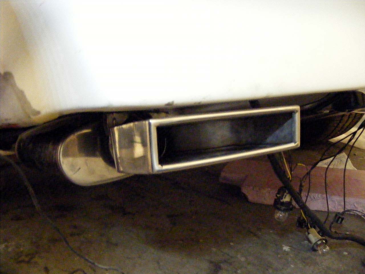
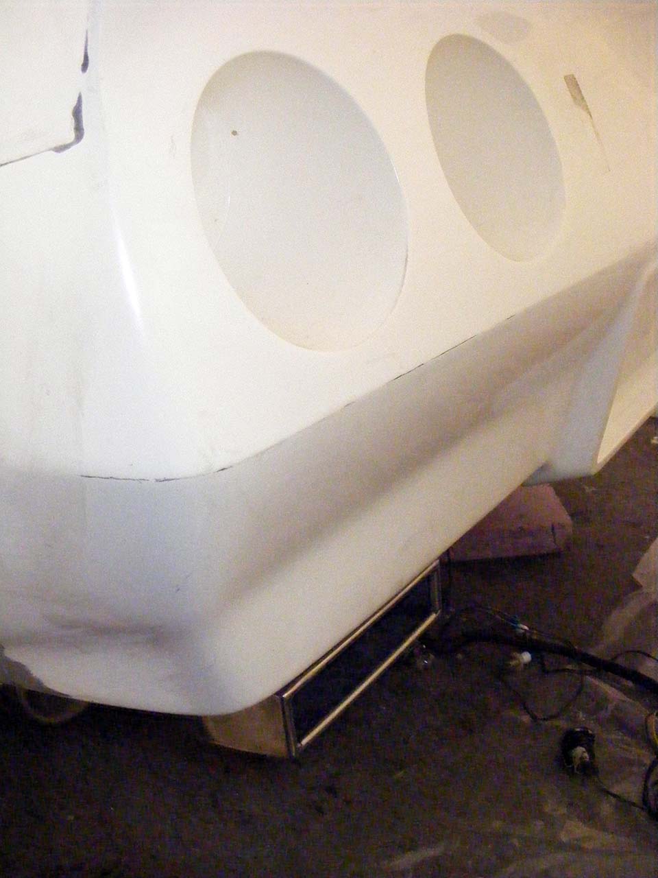
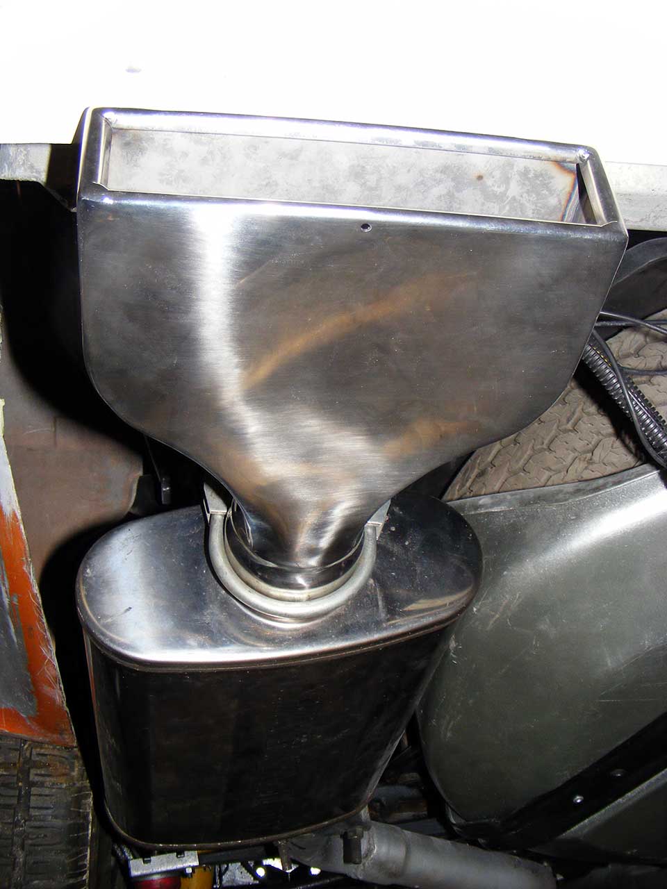
They're called LT-1 tip, and I'm pretty sure it's a copy of some of muscle car era.
Never have the ebay warping syndrome?
When object have the tendency to grow or shrink out of proportions between the moment you order them and the moment you receive them.
Well, those exhausts are the exception that proves the theory.
The size is just perfect.
I don't have much backup to get the big picture, but I feel it will look cool.
I will probably screen mesh them.
I've also resumed bodywork, small repair/modification that I'll document later. I don't want to get into big stuff before I've sealed my interior.
Santa knows I've been a good boy.
He knows I've spent days polishing my SS trims
I did 600/800/1000/1200 (all but 600 are wet sanding), polish on hard wheel with black compound then polish on smooth wheel with green compound.
Both polishing have been done in two passes, one hard then one smooth.
Then test-installed the whole setup :
By the way if someone has a close pic of the screws that goes on top of the T trim, that would be cool.
So since I've done my homework, Santa made sure I receive all the cool stuff I ordered.
First is something I've been searching for a while.
Glass fuse to Blade fuse adapter.
I ordered a pack of 8 and only received 7, I'm sure they will sort this out.
How many time I broke the glass fuse while trying to remove it.
Next gift is a pair of DRL/Flasher combo.
I'm kind of torn. If I was listening to the crazy in my, I'd cut the bumper and put them in, same position as picture, just higher.
That would be cool, but those unit are not designed to work at such a steep angle. They are bevel shaped, just not enough.
With those mounted flush to the bumper, the light would be spread outward.
How bad would it be? well, I think I need to make some real life tests to find out.
Last gift, is a pair of exhaust tips.
They're called LT-1 tip, and I'm pretty sure it's a copy of some of muscle car era.
Never have the ebay warping syndrome?
When object have the tendency to grow or shrink out of proportions between the moment you order them and the moment you receive them.
Well, those exhausts are the exception that proves the theory.
The size is just perfect.
I don't have much backup to get the big picture, but I feel it will look cool.
I will probably screen mesh them.
I've also resumed bodywork, small repair/modification that I'll document later. I don't want to get into big stuff before I've sealed my interior.
Last edited by Denpo; 08-18-2017 at 09:57 PM.