Fuel Injection Percolation Issue Improvements
#1
Team Owner


Thread Starter
Member Since: May 2005
Location: Madison - just west of Huntsville AL
Posts: 31,361
Received 1,283 Likes
on
732 Posts

OK, started a new thread for this issue, and copied two pertinent posts for this topic. Jump in with additional info please
From jim lockwood:
Ed, the Reader's Digest version of my modifications includes:
1. Converting fuel path to circulate fuel through the spider hub and back to the bowl, similar to what is done on Sting Ray FI (my FI is for a C1).
2. Breaking the thermally conductive path between the nozzles and the rest of the FI unit. Nozzles pick up significant heat through conduction.
3. Replacing the spider supply and return lines with tubing which has higher thermal resistance than the factory copper lines.
Other changes I've tried, none of which helped:
1. Insulating the fuel pipe from engine pump to FI
2. Insulating the fuel tube from fuel meter to spider
3. Use of thick '57-era one piece plenum gasket
4. Adding a thermal barrier between the spider hub and the underside of the doghouse
Since fuel perc happens only at idle and is due to the near-zero idle fuel pressure, I'm developing a high pressure idle fuel system. This shows significant promise but its operation is kinda crude and needs more work.
Mike, the fuel we have to use out here in the People's Republik doesn't even smell like gasoline. With summer fuel and an unmodified FI unit, 80 degree temps can provoke fuel perc. With winter fuel, I've endured fuel perc when temperatures were in the mid 60s.
With my modified FI I've driven in stop and go traffic when temps were in the high 90s without observing fuel perc. Me, I was melting, but the FI was well behaved.
Jim
From Rdelvalle:
There are several things we did to my Vette that has helped with the percolation issue. The fuel injection unit is like brand new since we completely rebuilt it. The gear pump was rebuilt by Rollin Jones at the advice of Jim. Also the calibration and tuning was done under Jim's guidance. In addition I have new spark plug harness, new distributor cap and rotor an new spark plugs NGK Iridium 0.040 in gap, new coil and electronic ignition. Of course these are not the fixes but I think that having all these in place contributes to solving the problem. I also have an MSD Street Fire installed. You need the basics to be in top shape or they will exacerbate the problem.
Now for the things I think are the key contributors to the percolation problem resolution here is the list:
1- Electronic Fuel pump: We located the pump on the right side wheel well. This keeps the pump cool since air is blowing pass it when the car is in motion. The mechanical pump is attached to engine block and is a heat absorb-er that raises the gasoline temperature close to boiling point.
2- Installed a marine in line bilge fan with 120 CFM blowing directly into the spider. It get fresh air from the fuel injection air intake duct. I have a Y in the duct that supplies outside air to the spider.
3- I use non-ethanol 90 octane gas better known in South Florida as Rec90. I experimented with E10 93, AV 110 octane and the Rec90. The AV gas cost $14.40 per gallon so not an option. I have been using the Rec90 for almost two years and I swear by it. We did a lot of experimentation with the gas and Rec90 made a significant difference.
4- Insulated the gasoline line from the pump to the fuel injection gas filter.
If you guys are interested I can post the details of the pump and the fan with photos, let me know.
Regards
Roberto
The following 2 users liked this post by emccomas:
Dan Hampton (11-29-2020),
Loren Smith (11-27-2020)

Popular Reply
11-18-2020, 01:13 PM
Race Director


Member Since: Feb 2007
Location: northern california
Posts: 13,629
Received 6,546 Likes
on
3,010 Posts
C2 of Year Finalist (track prepared) 2019

Ed, the Reader's Digest version of my modifications includes:
1. Converting fuel path to circulate fuel through the spider hub and back to the bowl, similar to what is done on Sting Ray FI (my FI is for a C1).
2. Breaking the thermally conductive path between the nozzles and the rest of the FI unit. Nozzles pick up significant heat through conduction.
3. Replacing the spider supply and return lines with tubing which has higher thermal resistance than the factory copper lines.
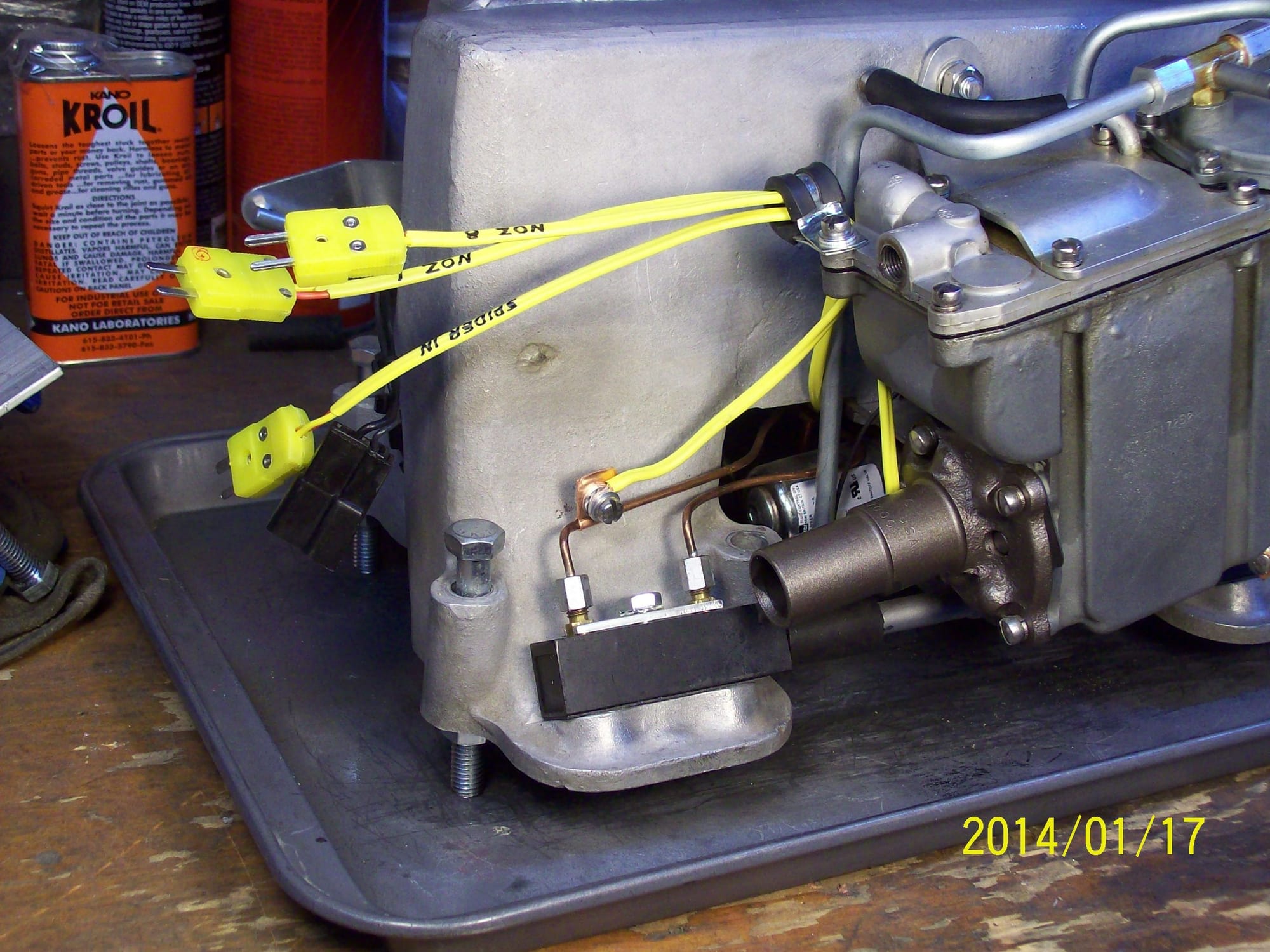
Among the many things I learned was that fuel perc could happen with summer fuel once the nozzle line temperatures reached 135F-140F, well below normal engine operating temperatures! With winter fuel, the onset of fuel perc could happen with nozzle line temperatures as low as 105F -110F. Of course this is with the motor fuel sold here in the Peoples Republik of Kalifornia.
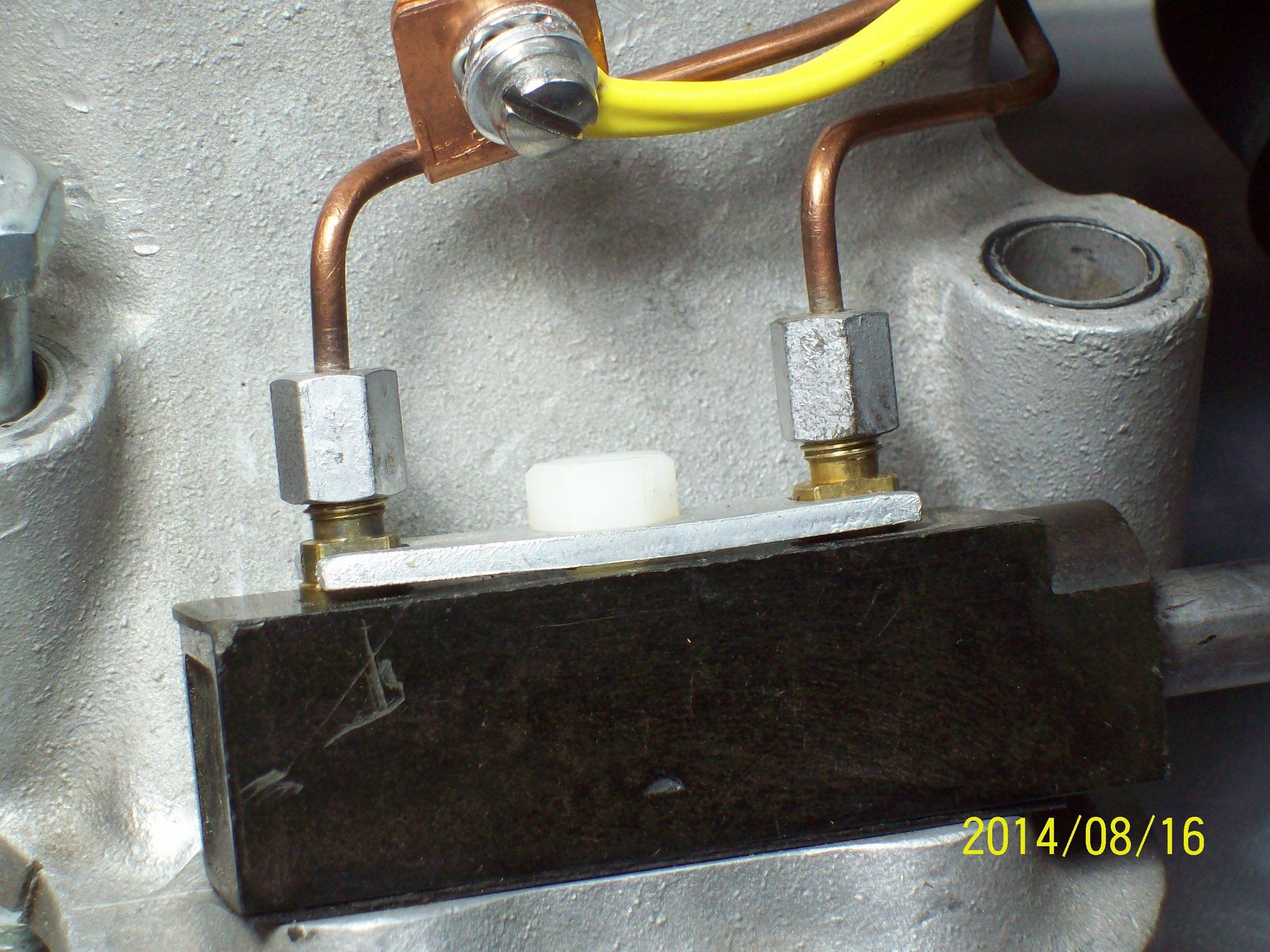
While I had the ability to measure temperatures, I wondered how much heat was being conducted to the nozzles. The conduction path is the plenum, the nozzle hold down bolt, the flat nozzle retainer, and finally the nozzle itself. To break this path, I replaced the steel hold down bolt with a nylon bolt as shown below:
Something to know: When you shut off a hot FI engine, heat rises and FI temperatures increase. Of course that means that nozzle and nozzle line temps increase.
What I immediately discovered was that after a hot start, nozzles retained by the nylon bolt cooled back to a more normal temperature significantly quicker than did nozzles retained by a metallic bolt. What this meant was that recovery from fuel perc would take less time and might even be postponed since the only source of nozzle heating became radiated heat.
Based on the results of this experiment, I replaced all of the nozzle retainer bolts with nylon.
All C1 FI units have a one-way fuel path from the Fuel Meter out to the nozzles. Fuel in any of the lines has plenty of time to heat soak and to partially vaporize, resulting in fuel perc.
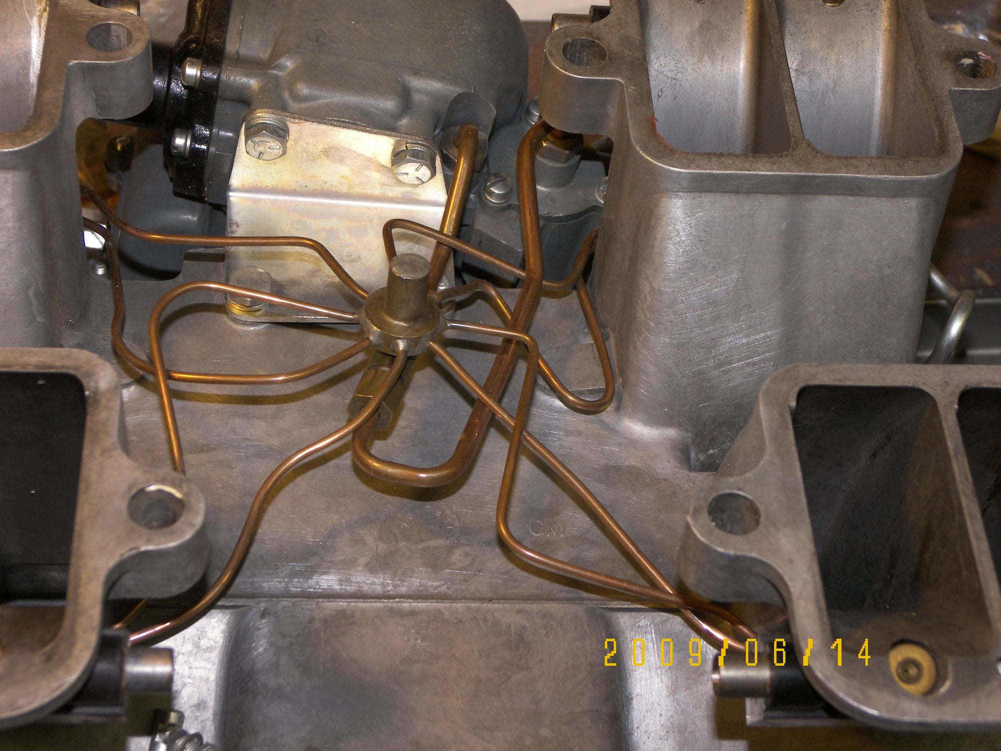
Sting Ray FI units are less susceptible to fuel perc than C1 FI units because fuel constantly circulates from the Fuel Meter to the spider and back to the Fuel Meter. To achieve this circulation, Sting Ray Fuel Meters have two fuel ports, one of which supplies fuel to the spider and the other which returns fuel to the fuel bowl. You can see those ports in this picture:
After thinking about it, I realized it would be possible to modify a C1 Fuel Meter such that it, too, could have a fuel supply port and a fuel return port. That would permit me to install a Sting Ray-like spider to let fuel constantly circulate. My first implementation of this idea looked like this:
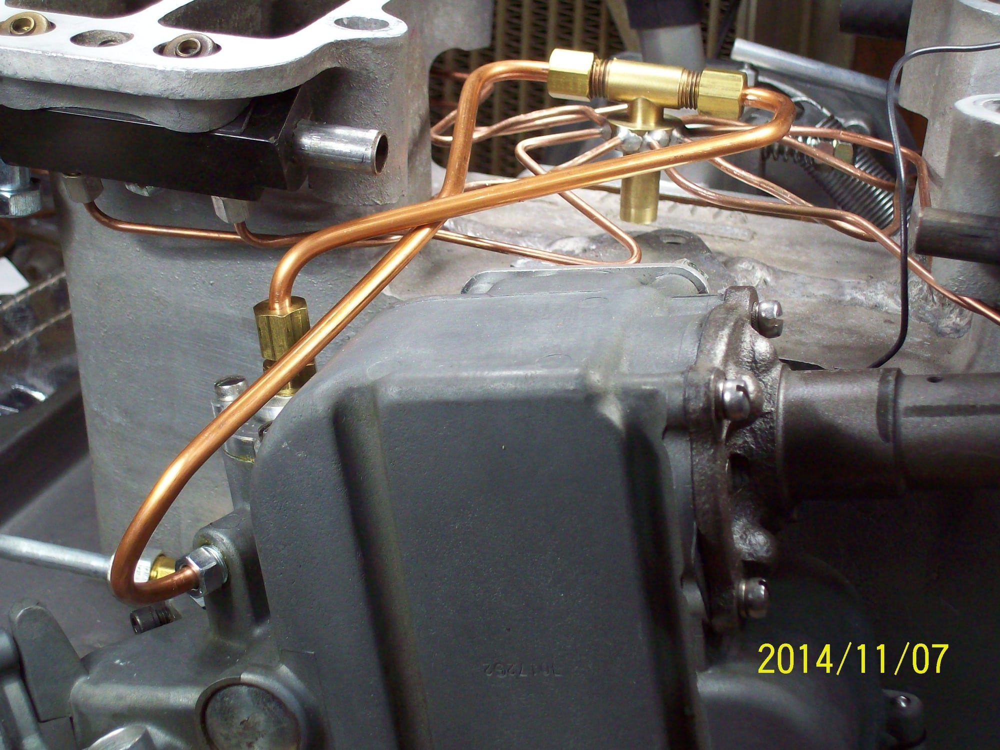
Fuel flow is out the bottom of a custom fabricated spill valve cover, to the spider, and back to the Fuel Meter entering in the port on the side.
The effect this one change had on the propensity for fuel perc was dramatic.
I conducted an experiment in which I compared the behavior of this modified FI to a bone-stock FI. Under conditions which were as nearly identical as I could achieve (90F ambient temps, same 22 mile warm up drive), the time required for the onset of fuel perc during extended post-drive engine idling looked like this:
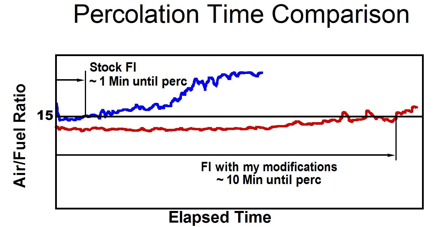
This was a pretty significant improvement but I still occasionally would encounter traffic situations in which I could tell the engine was becoming unhappy. I needed to do more.
I initially tried insulating the supply and return lines between the spider and the Fuel Meter. If that made any difference at all, I couldn't measure it with my instruments.
Somewhere along the way, it dawned on me to wonder why copper tubing was used to route fuel to the nozzles. Copper is a terrific conductor of heat and seemed like a terrible material choice. I decided to replace the copper supply and return lines with steel lines which conduct heat much more poorly than copper. The result looks like this:
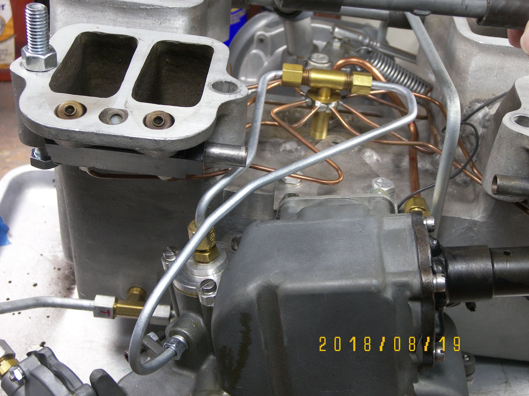
And this is where my mongrel FI unit is today. With the three changes I've just described, I've driven around in stop and go traffic on days when the temps were in the high 90s. The engine in my car never missed a beat although I was hot and sweaty.
Is this a single point solution? That is, would it work for other FI owners as well as it works for me? We'll find out. Another CF member has modified his C1 FI unit to include the Sting Ray-like fuel re-circulation. I don't believe he has yet put significant miles on his car so that jury is still out. Another data point will come from a unit I've been asked to modify in the exact way I modified my own unit. I'll be road testing that FI unit soon.
In development but not ready for prime time is an idea I've had to get around the inherent limitations caused by nearly zero FI fuel pressure at idle. That will be the subject of another posting.
Jim
#2
Yes , I would like to see what exactly you did, although the amount of driving time for my 64 is unknown at this time. Thanks
#3
Team Owner


Thread Starter
Member Since: May 2005
Location: Madison - just west of Huntsville AL
Posts: 31,361
Received 1,283 Likes
on
732 Posts

OK, I have a few questions for Jim and Roberto:
Jim, what year ands model is your FI system. I know you said C1. Can you be more specific? Also, can you describe your efforts on the idle fuel pressure increase. I have heard similar suggestions, but no solutions yet that I know of.
Roberto, Please do post pictures of the fan and duct work to the spider, and as well as details of the fuel pump, pictures, etc. I also assume from your post that you removed the mechanical fuel pump, is that correct? What electronic fuel pump did you choose to use. I may go with an in tank pump in preparation for my EFI conversion (one of these days).
The thought crossed my mind to use something line an in tank fuel pump, and keep the mechanical pump on the engine, but guts the insides and make it just a straight pass through. Yes, this would be an attempt to keep it looking stock.
I also wondered about an additional pump or pump regulator or "something" mounted inside the fuel meter that bumps the fuel pressure up to the spider.
I admit that I do not know how these things work. I understand (without specifics) that the spider is more than just a distribution block. There is some sort of spring / value / whatever inside the spider.
Isn't the Rochester FI unit a constant flow unit. BY that I mean that when the engine is running, all 8 cylinders have fuel going to them all of the time, but the fuel only gets into the cylinder when the intake valve opens. It is not like a timed FI unit that sprays fuel only when needed, am I correct? Yes, I know my ignorance of this topic is astounding, especially since I own a 64 FI unit.
Ken Hansen told me that the fuel pressure in each of the spider lines is something like 1/4 of a pound. Does that sound right?
How hard would it be to increase the fuel pressure, and what is the down side to increasing the fuel pressure across the RPM range? I assume that is what actually happens, the fuel pressure increases as the RPMs increase. I am guess this is due to the increased turning speed of the fuel pump from the distributor to the fuel meter.
I can certainly see how electronics would help a lot in these situations, and also sort of see the challenges to working on a mechanical FI unit.
The last time I took my 64 out it ran great, and did not stumble once. It was still hard to start, much harder that it was when we first installed the FI unit, so there is still something wrong. Once I get my 56 BelAir moveable ()wheels and tires back on it) I am going to putt that FI and send it to Ken Hansen. I am really whishing now that I had insisted on a new spider. I suggested it when Ken was rebuilding the unit, and he said the spider checked out OK. He also said he now suspects the spider, based on my description of the issues.
Back to percolation, I know of a person with a 62 FI car that had to drive the car from Tennessee to Florida and back. I believe he said it was in the spring time, so not excessively hot, but still hot enough. And of course he had to use pump gas. He identified the ethanol free stations on his route and made sure to stop at those for fuel.
But he also made a fiberglass (hand laid) set of duct work that brought cool air in from the front of the car and blew it directly on the spider. The duct work had a couple of small muffin electric fans that ran off of a toggle switch in the car. He attached it temporarily to the engine with some home made brackets. He said that system allowed him to drive back and forth to Florida with no problem, and removing it was very easy afterwards. No permanent modifications. The car was a 62 but it had a highly modified engine along with a modified 62 injector system.
OK, another question... other than the spider, what other parts of the FI unit (or anything else for that matter) need to be cooled down. I think I read something about the heat from the mechanical fuel pump on the engine. I wonder if a no conductive block of material mounted between the engine and the fuel pump would help.
Last edited by emccomas; 11-18-2020 at 03:07 AM.
The following 2 users liked this post by emccomas:
freezplugz (05-03-2022),
Loren Smith (11-27-2020)
#4
Race Director


Member Since: Feb 2007
Location: northern california
Posts: 13,629
Received 6,546 Likes
on
3,010 Posts
C2 of Year Finalist (track prepared) 2019

Ed et al,
First comments to your posting and then I'll get into what I've done.
The FI unit which is the victim of my endless tinkering and experimenting most closely resembles a '60 - '61 7320 unit. It is a mongrel FI that I assembled from pieces and parts that I had, parts that I acquired, and parts which I designed and had fabricated.
I'm gong to make three postings: This one, one to describe what I've done to date, and one to describe what I'm developing. In the last posting I'll describe what I'm doing about idle fuel pressure.
That would not work, Ed. The low idle fuel pressure is an integral part of the engineering which went into Rochester FI. If you boost the idle fuel pressure you will upset the idle air/fuel mixture.
There is a check valve at the hub of all FI spiders. On your FI unit, that check valve is forced closed by a spring which pushes the needle UP into the seat. On '62 and older FI units, check valve is gravity operated; the weight of the needle tends to pull it DOWN into the seat.
Yes.
Ken Hansen told me that the fuel pressure in each of the spider lines is something like 1/4 of a pound. Does that sound right?
Ken is right. The idle fuel pressure is extremely low, the exact pressure being a function of nozzle flow rates and engine needs.
The key concept is that fuel perc happens because the idle fuel pressure is less than the fuel vapor pressure when the engine is warm. As such you get partial vaporization of the fuel in parts of the FI where you want it to remain liquid and then the engine begins to idle poorly.
It would be a challenge. You would have to find a way to manufacture nozzle orifice discs with almost microscopic orifices so that more fuel pressure would actually be needed to keep the overall flow the same. The orifices in your FI are already tiny, being on the order of .014". In pre-'63 units orifices are even smaller at approximately .011".
I suspect there could be a domino effect from raising the fuel pressure across the board.
You might need to develop a more robust drive cable for the gear pump. The strength of the axle/link might need to be improved. Too the geometry of the axle/link lever arm would have to be changed You might need to do development work on the spill valve to make it more robust and to compensate for the higher fuel pressure. And on and on....
.
Anything that reduces the temperature of the spider and the nozzle lines helps.
Anything in contact with fuel needs to be kept as un-hot as possible and practical. Thermally isolating the engine mounted pump or avoiding it all together, as Roberto has done, is a significant step in the right direction.
Jim
First comments to your posting and then I'll get into what I've done.
Also, can you describe your efforts on the idle fuel pressure increase. I have heard similar suggestions, but no solutions yet that I know of.
I also wondered about an additional pump or pump regulator or "something" mounted inside the fuel meter that bumps the fuel pressure up to the spider.
. I understand (without specifics) that the spider is more than just a distribution block. There is some sort of spring / value / whatever inside the spider.
Isn't the Rochester FI unit a constant flow unit.
Ken Hansen told me that the fuel pressure in each of the spider lines is something like 1/4 of a pound. Does that sound right?
The key concept is that fuel perc happens because the idle fuel pressure is less than the fuel vapor pressure when the engine is warm. As such you get partial vaporization of the fuel in parts of the FI where you want it to remain liquid and then the engine begins to idle poorly.
How hard would it be to increase the fuel pressure, and what is the down side to increasing the fuel pressure across the RPM range? I assume that is what actually happens, the fuel pressure increases as the RPMs increase. I am guess this is due to the increased turning speed of the fuel pump from the distributor to the fuel meter.
I suspect there could be a domino effect from raising the fuel pressure across the board.
You might need to develop a more robust drive cable for the gear pump. The strength of the axle/link might need to be improved. Too the geometry of the axle/link lever arm would have to be changed You might need to do development work on the spill valve to make it more robust and to compensate for the higher fuel pressure. And on and on....
.
But he also made a fiberglass (hand laid) set of duct work that brought cool air in from the front of the car and blew it directly on the spider. The duct work had a couple of small muffin electric fans that ran off of a toggle switch in the car. He attached it temporarily to the engine with some home made brackets. He said that system allowed him to drive back and forth to Florida with no problem, and removing it was very easy afterwards. No permanent modifications. The car was a 62 but it had a highly modified engine along with a modified 62 injector system.
OK, another question... other than the spider, what other parts of the FI unit (or anything else for that matter) need to be cooled down. I think I read something about the heat from the mechanical fuel pump on the engine. I wonder if a no conductive block of material mounted between the engine and the fuel pump would help
Jim
The following users liked this post:
Loren Smith (11-27-2020)
#5
Pro


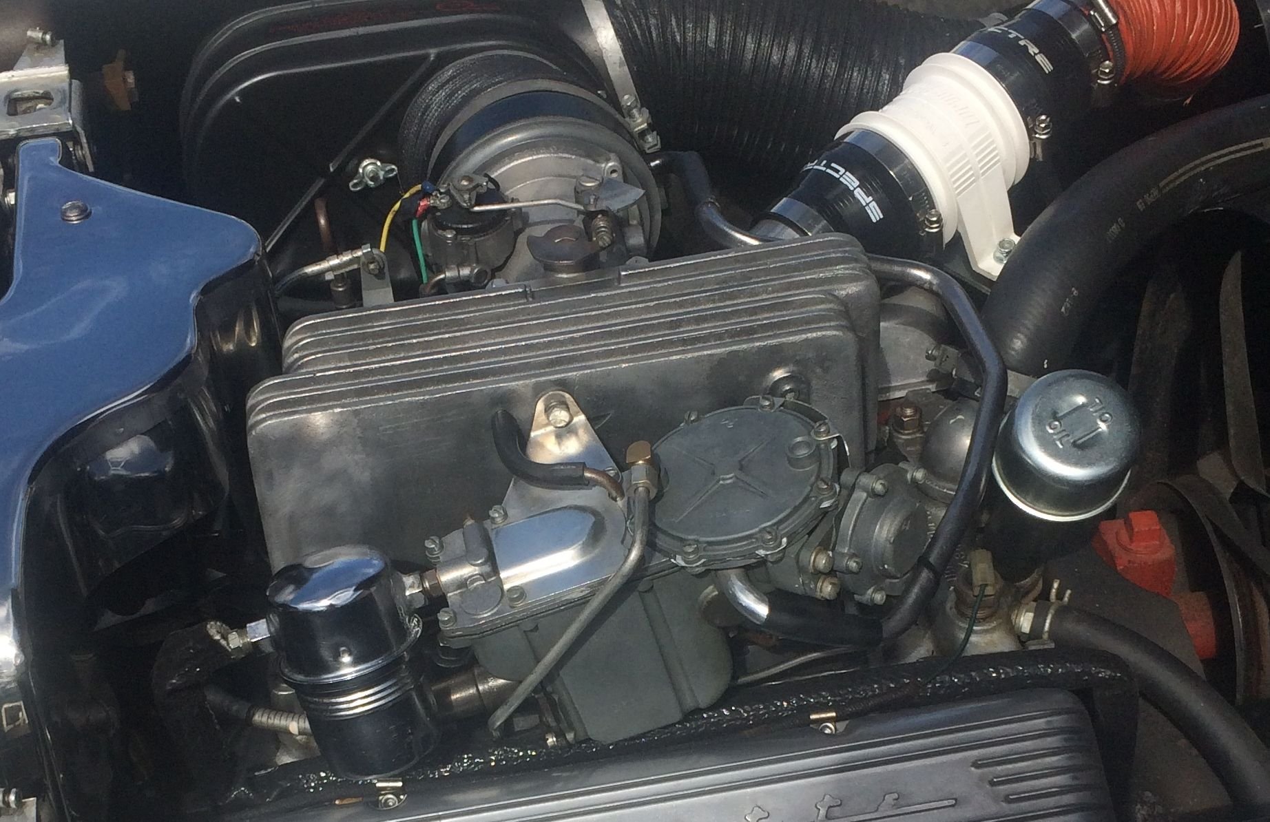
Gas line insulation from fuel pump to FI gas filter can. Upper right corner, blower system
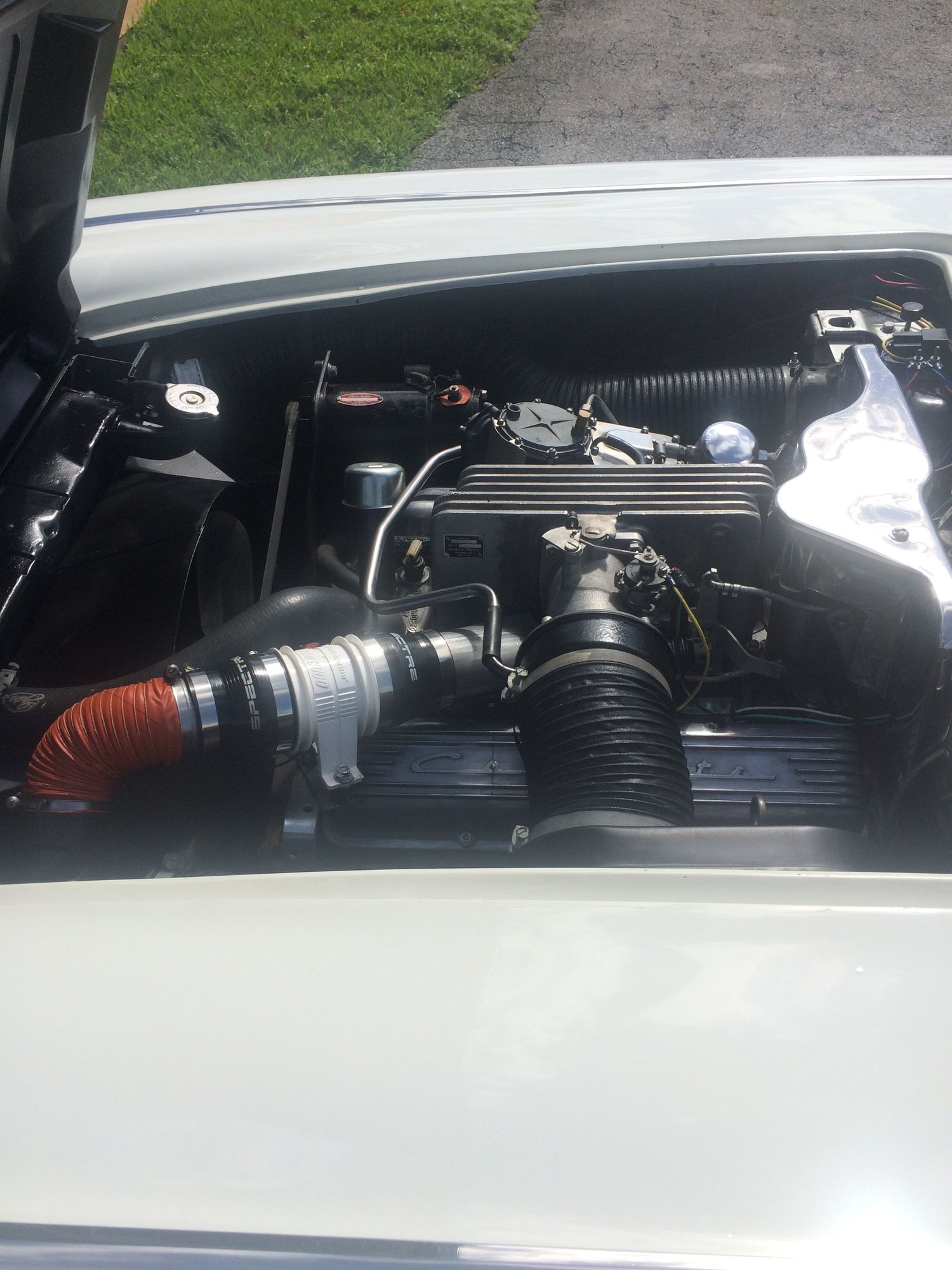
Marine turbo fan 120 CFM blower system
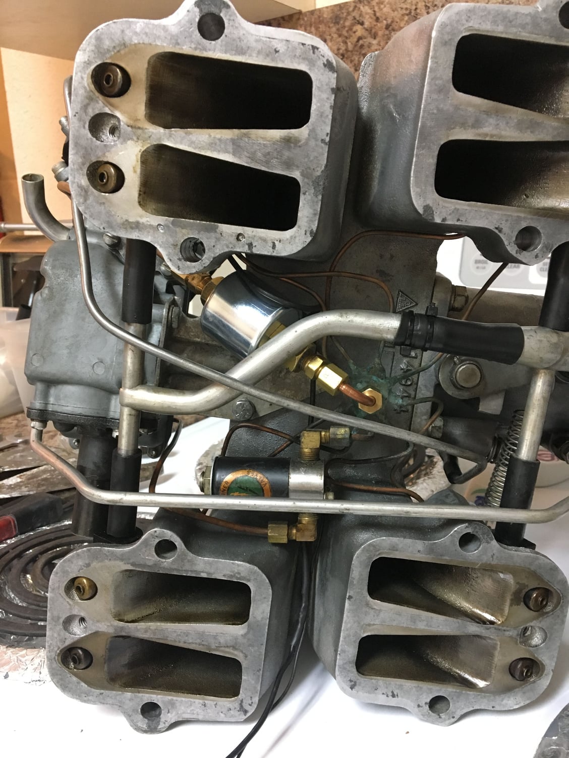
Anti siphon solenoid and priming solenoid. Priming solenoid is great when I first start the car after sitting for days. Also in the event that I get a hot start the priming solenoid comes in to the rescue.
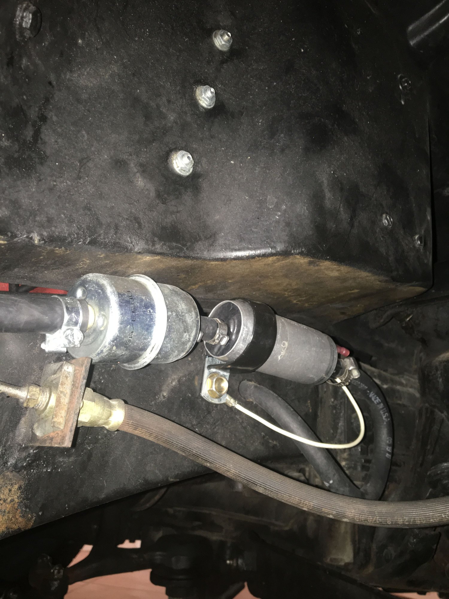
Electric Fuel pump. Attached to the frame via one screw that also serves as a ground. Right wheel well. The pump can be changed in fifteen minutes. The mechanical pump was completely eliminated. There is a metal plug that you can buy to close the hole.
The following 3 users liked this post by Rdelvalle:
#6
Pro


Here is list of parts:
West Marine Turbo In-Line Exhaust Blower 3 inch 120 CFM
Spectre 3.5 x 3 inch reducer coupler
Flexible red Silicone Coated air Duct Induction duct pipe cold
The piece that attaches to the output of the fan and to the reducer is lead pipe that we flattened at the end like a duck bill to speed the flow.
The red air duct is connected to the FI air intake duct. We did this with a PVC "T" from home depot. The "T" fits between the duct entrance end and the metal connector where the duct is connected to the outside of the engine.
We made a couple of brackets, aluminum, to attached the fan to the engine block. There were two available holes. You need to run a wire for power to the fan.
Electric Fuel Pump: Carter in-line P60504 or equivalent. I think there is anew number for this part which is equivalent. I have a spare one and as you can see from the photo it is very easy to replace. I have no pressure regulator or anything else attached to the pump. Where it sits in the wheel well it get plenty of cooling when the car is moving as air flows into that area. Probably one of the main contributors to the resolution of the percolation problem
DEI Engineering #010472 5/8" x 3' Fire Sleeve. This is the Gas line insulation I used.
Very important I use non-ethanol gasoline better known in South Florida as Rec90. We did a lot of experimentation with E10 93 AV 100+ gas and Rec90. The latter is by far the best and most economical choice if you can get it. I will say that the non-ethanol gas is a very important piece of the percolation resolution problem.
Last edited by Rdelvalle; 11-18-2020 at 12:31 PM.
#7
Race Director


Member Since: Feb 2007
Location: northern california
Posts: 13,629
Received 6,546 Likes
on
3,010 Posts
C2 of Year Finalist (track prepared) 2019

Ed, the Reader's Digest version of my modifications includes:
1. Converting fuel path to circulate fuel through the spider hub and back to the bowl, similar to what is done on Sting Ray FI (my FI is for a C1).
2. Breaking the thermally conductive path between the nozzles and the rest of the FI unit. Nozzles pick up significant heat through conduction.
3. Replacing the spider supply and return lines with tubing which has higher thermal resistance than the factory copper lines.
1. Converting fuel path to circulate fuel through the spider hub and back to the bowl, similar to what is done on Sting Ray FI (my FI is for a C1).
2. Breaking the thermally conductive path between the nozzles and the rest of the FI unit. Nozzles pick up significant heat through conduction.
3. Replacing the spider supply and return lines with tubing which has higher thermal resistance than the factory copper lines.

Among the many things I learned was that fuel perc could happen with summer fuel once the nozzle line temperatures reached 135F-140F, well below normal engine operating temperatures! With winter fuel, the onset of fuel perc could happen with nozzle line temperatures as low as 105F -110F. Of course this is with the motor fuel sold here in the Peoples Republik of Kalifornia.
While I had the ability to measure temperatures, I wondered how much heat was being conducted to the nozzles. The conduction path is the plenum, the nozzle hold down bolt, the flat nozzle retainer, and finally the nozzle itself. To break this path, I replaced the steel hold down bolt with a nylon bolt as shown below:

Something to know: When you shut off a hot FI engine, heat rises and FI temperatures increase. Of course that means that nozzle and nozzle line temps increase.
What I immediately discovered was that after a hot start, nozzles retained by the nylon bolt cooled back to a more normal temperature significantly quicker than did nozzles retained by a metallic bolt. What this meant was that recovery from fuel perc would take less time and might even be postponed since the only source of nozzle heating became radiated heat.
Based on the results of this experiment, I replaced all of the nozzle retainer bolts with nylon.
All C1 FI units have a one-way fuel path from the Fuel Meter out to the nozzles. Fuel in any of the lines has plenty of time to heat soak and to partially vaporize, resulting in fuel perc.
Sting Ray FI units are less susceptible to fuel perc than C1 FI units because fuel constantly circulates from the Fuel Meter to the spider and back to the Fuel Meter. To achieve this circulation, Sting Ray Fuel Meters have two fuel ports, one of which supplies fuel to the spider and the other which returns fuel to the fuel bowl. You can see those ports in this picture:

After thinking about it, I realized it would be possible to modify a C1 Fuel Meter such that it, too, could have a fuel supply port and a fuel return port. That would permit me to install a Sting Ray-like spider to let fuel constantly circulate. My first implementation of this idea looked like this:

Fuel flow is out the bottom of a custom fabricated spill valve cover, to the spider, and back to the Fuel Meter entering in the port on the side.
The effect this one change had on the propensity for fuel perc was dramatic.
I conducted an experiment in which I compared the behavior of this modified FI to a bone-stock FI. Under conditions which were as nearly identical as I could achieve (90F ambient temps, same 22 mile warm up drive), the time required for the onset of fuel perc during extended post-drive engine idling looked like this:

This was a pretty significant improvement but I still occasionally would encounter traffic situations in which I could tell the engine was becoming unhappy. I needed to do more.
I initially tried insulating the supply and return lines between the spider and the Fuel Meter. If that made any difference at all, I couldn't measure it with my instruments.
Somewhere along the way, it dawned on me to wonder why copper tubing was used to route fuel to the nozzles. Copper is a terrific conductor of heat and seemed like a terrible material choice. I decided to replace the copper supply and return lines with steel lines which conduct heat much more poorly than copper. The result looks like this:

And this is where my mongrel FI unit is today. With the three changes I've just described, I've driven around in stop and go traffic on days when the temps were in the high 90s. The engine in my car never missed a beat although I was hot and sweaty.
Is this a single point solution? That is, would it work for other FI owners as well as it works for me? We'll find out. Another CF member has modified his C1 FI unit to include the Sting Ray-like fuel re-circulation. I don't believe he has yet put significant miles on his car so that jury is still out. Another data point will come from a unit I've been asked to modify in the exact way I modified my own unit. I'll be road testing that FI unit soon.
In development but not ready for prime time is an idea I've had to get around the inherent limitations caused by nearly zero FI fuel pressure at idle. That will be the subject of another posting.
Jim
The following 13 users liked this post by jim lockwood:
64Fuel (11-18-2020),
Dan Hampton (11-18-2020),
esema (11-20-2020),
jerry gollnick (01-04-2024),
K2 (11-18-2020),
and 8 others liked this post.
#8
Drifting


Member Since: Jul 2010
Location: Minnesota
Posts: 1,277
Received 423 Likes
on
249 Posts
2023 C1 of the Year Finalist - Modified
2020 Corvette of the Year Finalist (track prepared))
2019 C1 of Year Finalist (track prepared)

Jim, excellent info. I put a lot of faith in your recommendations.
I tried insulating fuel lines and made a ceramic board insulator to place under the spider in my '57. I don't believe these mods have made any difference in my mild percolation problem.
Are the nylon bolts you used in the nozzle blocks readily available? Did you make a threaded hole in the bowl for the return line? Any chance that you could produce a kit with the steel fuel lines?
The following users liked this post:
After38Years (09-12-2021)
#9
Intermediate


Good discussion guys. Nice work Jim and Roberto.
I have a 375R unit on my 64 and get serious percolation but mostly just on hot restarts using E10. It always clears up in a few minutes after cooler fuel is running through the system. This is in Ohio with milder temperatures than south Florida, but in hotter summer months I switch to 100LL aviation gas, it never percolates for me and I can get it for under $5 per gallon.
I like to experiment too, so this past spring while running E10, I hooked up a data logger with four thermocouples attached to: the spider hub, inside the intake air duct, inside the fuel bowl, and in the engine well away from the engine. Went for several rides with stops and restarts over a few days time and collected data. Like Jim, I found that percolation begins to be an issue at fairly low temperatures, in my case when the spider hub reached as low as 110F. I had winter fuel in the tank at the time so that may be a factor. Was also experimenting with Peltier cooling devices but concluded it would be impractical to use them to solve the hot spider problem. They're extremely inefficient at cooling, and make way more heat than they remove.
Question for Roberto: do you run your blower with engine off between starts to offset heat soak from the engine block? Or do you run it while driving? Both?
Dave
#11
Race Director


Member Since: Feb 2007
Location: northern california
Posts: 13,629
Received 6,546 Likes
on
3,010 Posts
C2 of Year Finalist (track prepared) 2019

Jim, excellent info. I put a lot of faith in your recommendations.
I tried insulating fuel lines and made a ceramic board insulator to place under the spider in my '57. I don't believe these mods have made any difference in my mild percolation problem.
Are the nylon bolts you used in the nozzle blocks readily available? Did you make a threaded hole in the bowl for the return line? Any chance that you could produce a kit with the steel fuel lines?
I tried insulating fuel lines and made a ceramic board insulator to place under the spider in my '57. I don't believe these mods have made any difference in my mild percolation problem.
Are the nylon bolts you used in the nozzle blocks readily available? Did you make a threaded hole in the bowl for the return line? Any chance that you could produce a kit with the steel fuel lines?
The fellow who wants me to modify his FI unit to be like my mongrel FI had previously tried a ceramic board between the adapter plate and the spider. His conclusion about its effectiveness was the same as yours.
The nylon bolts are available from Amazon:
Regarding the return line, I didn't make any irreversible modifications to the Fuel Meter. I didn't drill any holes.
Go back to my last picture, the one which shows my mongrel FI after I replaced the copper fuel lines with steel lines.
In a normal '58 - '62 FI unit, fuel flows out of the Fuel Meter via the fitting on the outboard side of the Fuel Meter. I reversed the flow and that port is now the return port for fuel. Fuel flows out the bottom of the Fuel Meter through a new port in a special Spill Valve cover I designed
The following users liked this post:
Todd H. (11-18-2020)
#12
Race Director


Member Since: Feb 2007
Location: northern california
Posts: 13,629
Received 6,546 Likes
on
3,010 Posts
C2 of Year Finalist (track prepared) 2019

I like to experiment too, so this past spring while running E10, I hooked up a data logger with four thermocouples attached to: the spider hub, inside the intake air duct, inside the fuel bowl, and in the engine well away from the engine. Went for several rides with stops and restarts over a few days time and collected data. Like Jim, I found that percolation begins to be an issue at fairly low temperatures, in my case when the spider hub reached as low as 110F. I had winter fuel in the tank at the time so that may be a factor.
Dave
#13
Pro


The blower comes on when I turn the switch to power on before cranking. So when I start the car I usually turn on the power and wait a few seconds for the blower to blow on the spider then I crank the engine. The blower stays on while I am driving it only turns off when I tun off the power. I do have a priming solenoid that I can bypass the spill valve and go directly from the FI fuel bowl to the spider. I use the priming solenoid when I have to start the car after a few weeks of not starting it. I do power on let the electric pump prime the system then I crank the starter and press the priming solenoid switch a couple of times. Starts right up after a couple of cranks. The priming solenoid is of great help if a hot start occurs.
Last edited by Rdelvalle; 11-18-2020 at 06:08 PM.
The following users liked this post:
Loren Smith (11-27-2020)
#14
Race Director


Member Since: Feb 2007
Location: northern california
Posts: 13,629
Received 6,546 Likes
on
3,010 Posts
C2 of Year Finalist (track prepared) 2019

My apology, Todd, for not seeing and responding to this question.
I'd be glad to modify anyone's '58 - '62 FI unit but I don't have a good way to produce kits. However, kits or not, the installation isn't a job for Do-It-Ur-Selfers.
I'd be glad to modify anyone's '58 - '62 FI unit but I don't have a good way to produce kits. However, kits or not, the installation isn't a job for Do-It-Ur-Selfers.
#16
Drifting


Great info on this percolation issue, because of this issue I’ve been on the fence with going thru all the work & money converting my 65 327/365 to a Rochester Fuel Injection unit I think they look great on a C2.
Has anyone tried replacing the spider assembly with braided stainless lines with teflon I.D.inners, sort of mimic what a lot of guys are running for brake calipers #3 teflon inner stainless braided outside?
Some sort of manifold/fuel log (for lack of words ) would have to be used & the fittings threaded onto it & the braided/teflon lines would come off it out to the nozzles?
Just a thought
Chalie
#17
Would decreasing the temperature of the incoming fuel help?
the gas tank is located directly above the exhaust.
the gas tank is located directly above the exhaust.
#18
Race Director


Member Since: Feb 2007
Location: northern california
Posts: 13,629
Received 6,546 Likes
on
3,010 Posts
C2 of Year Finalist (track prepared) 2019

Any tactic which reduces the fuel temperature will be beneficial. You can take that to the bank.
The temperature of the fuel reaching Roberto's FI unit is undoubtedly less by virtue of his outboard, electric fuel pump than it would be after passing through the normal engine mounted pump.
It would be interesting to instrument the fuel temperature both ways and see how much of a reduction he is achieving.
Jim
The following users liked this post:
64Fuel (11-20-2020)
#19
Pro


Jim,
I had not realized until you pointed out that the outboard electric pump is probably one of the biggest contributor to solving the percolation problem in my car. The reason we went to electronic fuel pump is to have more control of the fuel delivery not to address the percolation problem. The mechanical pump you have to crank the engine for it to work. The electrical pump I simply turn on the power for a few seconds and let it prime the lines also the spider turbo fan goes to work also. Then I crank the engine it starts right up. Still a few cranks because of the anti-siphon solenoid but still relatively fast. We lucked out because the electric pump and where we positioned it addressed the percolation problem without us realizing it. After you told me it dawn on me that it makes sense.
The mechanical pump attached to the engine block is a heat absorbing glutton. The gas in the mechanical pump gets very hot. The heat transfer happens very fast almost instantaneously thought all the lines and parts that move or store the gas. To your point the trick is to isolate the gasoline from absorbing heat as it moves for the tank to the nozzles.
Roberto
Last edited by Rdelvalle; 11-20-2020 at 10:41 AM.
The following 2 users liked this post by Rdelvalle:
64Fuel (11-20-2020),
Loren Smith (11-27-2020)
#20
Race Director


Member Since: Nov 2003
Location: Cottonwood AZ
Posts: 10,698
Received 3,050 Likes
on
1,935 Posts
C1 of Year Finalist (performance mods) 2019

A lot of good info has been stated here that I was not aware of when I was on the search for a nice mid year before I purchased my current 65. I wish I was aware of this before I bought. If I had known about these potential “fixes” as I probably would have purchase a nice 65 FI coupe that member stingray22 had for sale a couple of years ago. He has some NICE cars. 


