Anybody relocate LS coils off the valve covers?
 03-28-2014, 10:00 PM
#1
Melting Slicks


Thread Starter

Here's my dilemma, I really don't like the big plastic covers on top the LS motors, so my plan was to relocate the coils to the bottom side of the motor and get some custom valve covers for eye candy. Rich Z. shared a set of the coil mounting plates he used on his LS motor in a Street Shop chassis, but the SRIII chassis w/c6 control arms has the lower frame rail inboard much farther than his, so his setup won't fit. I could make a different shaped bracket for the passenger side which might fit, but the wiring would be real tight. Driver side, no way. I don't think it would be good to mount them on the lower back of the motor because of heat from the headers. The backside of the motor is too close to the firewall, so no room there. Bottom of the foot board is possible, but then some long spark plug wire runs.
Has anyone relocated their coils with an LS motor in a SRIII C6 chassis? Any ideas?
Thanks,
Ken
Has anyone relocated their coils with an LS motor in a SRIII C6 chassis? Any ideas?
Thanks,
Ken
Last edited by Ken Sungela; 03-28-2014 at 10:04 PM.
 03-29-2014, 06:34 AM
#2
Drifting

Here's my dilemma, I really don't like the big plastic covers on top the LS motors, so my plan was to relocate the coils to the bottom side of the motor and get some custom valve covers for eye candy. Rich Z. shared a set of the coil mounting plates he used on his LS motor in a Street Shop chassis, but the SRIII chassis w/c6 control arms has the lower frame rail inboard much farther than his, so his setup won't fit. I could make a different shaped bracket for the passenger side which might fit, but the wiring would be real tight. Driver side, no way. I don't think it would be good to mount them on the lower back of the motor because of heat from the headers. The backside of the motor is too close to the firewall, so no room there. Bottom of the foot board is possible, but then some long spark plug wire runs.
Has anyone relocated their coils with an LS motor in a SRIII C6 chassis? Any ideas?
Thanks,
Ken
Has anyone relocated their coils with an LS motor in a SRIII C6 chassis? Any ideas?
Thanks,
Ken
I relocated mine to the back side of the cylinder heads. This kept them high and dry and accessible for service if ever necessary. It was a fairly easily mod and only required a U shaped bracket that I fabricated from aluminum and used aluminum tube cut down for spacers to separate the coils. I then made a cover for them out of textured black ABS that spanned across the entire rear of the engine to keep them out of sight and also covered the oil sender unit.....really cleaned up the top of the engine. I'll have to dig out some pics for you, but there may be some here on the forum in a previous post.
R/
Jeff
 03-29-2014, 06:38 AM
#3
Drifting
Oh, and there are plenty of valve covers out there. I used Katech's, nice piece. I also like a pair I saw at the HRIA show that are billet aluminum, I'll post the name and link later...after some coffee and I wake up...hope some of the spelling is correct...keyboard is kinda blurry LOL.
03-29-2014, 09:37 AM
#4
Melting Slicks
Thread Starter
Thanks Jeff. I found one picture of your engine. I wasn't paying close attention when I last had my body on the chassis, but didn't think there was enough room behind the heads. I sense another body drop test fit in my future.
Yes, the Katech covers are cool.
I see you had a catch can for the PCV system. Do you think that's more of a requirement if you are racing the car and not really required for street use?
Thanks for your help.
Yes, the Katech covers are cool.
I see you had a catch can for the PCV system. Do you think that's more of a requirement if you are racing the car and not really required for street use?
Thanks for your help.
03-29-2014, 11:08 AM
#5
Tech Contributor
Member Since: Jun 2004
Location: I tend to be leery of any guy who doesn't own a chainsaw or a handgun.
Posts: 18,355
Received 768 Likes
on
550 Posts

Thanks Jeff. I found one picture of your engine. I wasn't paying close attention when I last had my body on the chassis, but didn't think there was enough room behind the heads. I sense another body drop test fit in my future.
Yes, the Katech covers are cool.
I see you had a catch can for the PCV system. Do you think that's more of a requirement if you are racing the car and not really required for street use?
Thanks for your help.
Yes, the Katech covers are cool.
I see you had a catch can for the PCV system. Do you think that's more of a requirement if you are racing the car and not really required for street use?
Thanks for your help.
There was a picture posted quite a while ago of an LS engine in a GrandSport replica. I can't find it, but that was the only other LS engine that I thought was an attractive engine.

 03-29-2014, 12:03 PM
#7
Drifting
Ken
I moved mine to the firewall with some nice brackets from ironworksspeedandcustom.com this car is a 69 but will work on a midyear also. Wires and coil ends are from Taylor. I have shields to protect & hide them. Am going to use polished script covers.
Mark
I moved mine to the firewall with some nice brackets from ironworksspeedandcustom.com this car is a 69 but will work on a midyear also. Wires and coil ends are from Taylor. I have shields to protect & hide them. Am going to use polished script covers.
Mark

 03-29-2014, 01:56 PM
#8
Melting Slicks
Thread Starter
[QUOTE=mark6669;1586527298]Ken
I moved mine to the firewall with some nice brackets from ironworksspeedandcustom.com this car is a 69 but will work on a midyear also. Wires and coil ends are from Taylor. I have shields to protect & hide them. Am going to use polished script covers.
Mark
Mark,
I bought some original valve covers I was thinking of modifying to get the "Corvette" script look on the covers. Where are you getting the polished script covers from?
03-29-2014, 03:12 PM
#10
Melting Slicks
Thread Starter
This is what I was going to make, someone beat me to it:
http://www.speedwaymotors.com/Finned...hed,34517.html
Or I can use original valve covers with these adapters:
http://www.speedwaymotors.com/COMP-C...ers,41789.html
http://www.speedwaymotors.com/Finned...hed,34517.html
Or I can use original valve covers with these adapters:
http://www.speedwaymotors.com/COMP-C...ers,41789.html
03-29-2014, 06:02 PM
#11
Hi Ken,
That's a shame they didn't work out...
Here are two other styles I saved pictures of from when I was thinking of options for mine...


I know I didn't have the room behind the heads for such a design and would have to of laid the coils 90 degrees so the profile would be less depth - which makes the stack very long.. The other issue was the wire connection points are on one end and coil plug on the other, making getting to one or the other more difficult..
To bad there isn't some space for you on the frame, down low, somewhere, because the plug wires sure route nice with the coils down low..
I know I did a lot of Google image searches for ideas when I made mine...
If I think of anything I will let you know..
Take Care,
Rich
That's a shame they didn't work out...
Here are two other styles I saved pictures of from when I was thinking of options for mine...
I know I didn't have the room behind the heads for such a design and would have to of laid the coils 90 degrees so the profile would be less depth - which makes the stack very long.. The other issue was the wire connection points are on one end and coil plug on the other, making getting to one or the other more difficult..
To bad there isn't some space for you on the frame, down low, somewhere, because the plug wires sure route nice with the coils down low..
I know I did a lot of Google image searches for ideas when I made mine...
If I think of anything I will let you know..
Take Care,
Rich
03-29-2014, 08:34 PM
#12
Melting Slicks

Member Since: Feb 2011
Location: Middletown Ohio
Posts: 2,892
Received 167 Likes
on
130 Posts
2016 C1 of Year Finalist
I saw a 57 Corvette at Goodguys in Columbus , O. last year which had the coil packs mounted below the spark plugs on a small block which has home made EFI on it. Pretty much out of sight.
03-30-2014, 08:55 AM
#13
Melting Slicks
Thread Starter
Hey Rich,
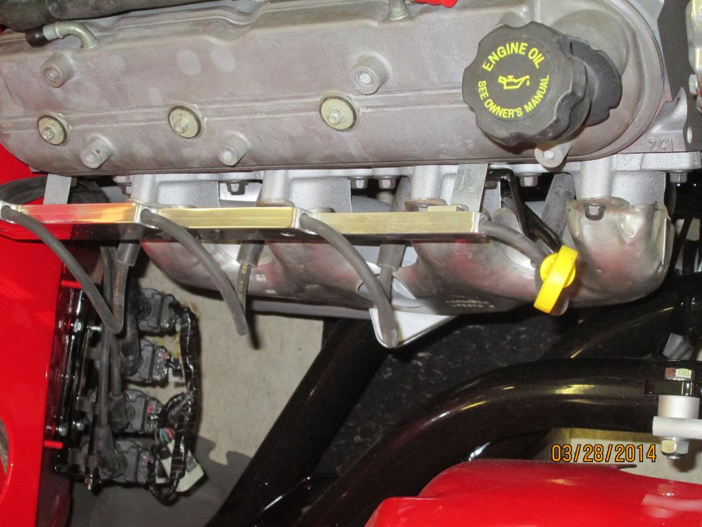
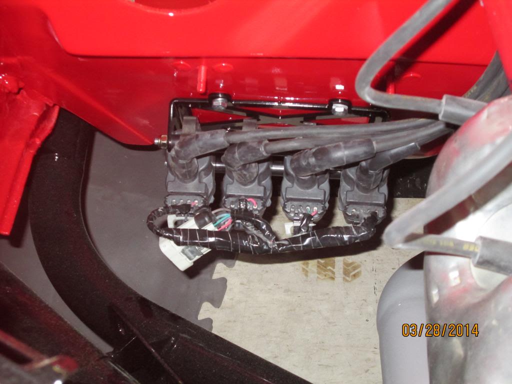
Yeah, I was disappointed they didn't bolt right in. I was looking at it again last night and think I could orient the 4 coils on the passenger side like the picture below and use 90 degree boots so I can bolt the bracket flat against the block. I may rotate it so the plug wire connections are pointed forward then use the 90 degree boots to loop them up to the plugs. I have to buy the connector for both ends,then mock it up to confirm clearance.
My motor sits back 2-3" more inches than Jeff's car shown above so there is no room behind the heads.
On the drivers side I could use a bracket like you show above but only if I put them in the back down low behind the headers which I don't really want to do because of heat. I can squeeze them in up front but only have 1/4" clearance to the frontrunner bracket up front and the motor mount in the rear. I'd have to make a custom bracket for that.
Where did you get your spark pug wire components? I remember you using something thicker than the 8.5 mm wires.
Does anyone have a wiring diagram for the coils? I know there are 2 ground, +12V, and the signal wire for each coil, but what's the color coding?
Thanks
Ken
03-30-2014, 04:31 PM
#14
Drifting
Thanks Jeff. I found one picture of your engine. I wasn't paying close attention when I last had my body on the chassis, but didn't think there was enough room behind the heads. I sense another body drop test fit in my future.
Yes, the Katech covers are cool.
I see you had a catch can for the PCV system. Do you think that's more of a requirement if you are racing the car and not really required for street use?
Thanks for your help.
Yes, the Katech covers are cool.
I see you had a catch can for the PCV system. Do you think that's more of a requirement if you are racing the car and not really required for street use?
Thanks for your help.
I used the catch can due to heavy flogging on the engine with lots of RPM. LS engines are a little prone to having oil huff through the "dirty" side of the vent system and will smutt up the intake over time. I never had a problem with mine and rarely had any real oil in the can...but it was there to catch what did come through. The LS7 has a little more PCV breathing with the dry sump tank than the wet versions.
R/
Jeff
03-30-2014, 07:47 PM
#15
Hi Ken,
I made my wires with components from Taylor - I know I have all the part numbers in my project thread. They were Thundervolt50 10.4mm, which is .409" in diameter. I then bought Taylor ends for the LS style coils, which I think only comes in the one angularity, but maybe it's different now.. Assembling wire that thick is a learning experience!
Here is the wire call out for the LS3/LS7 for the coils:
This first picture is the connection point on the coils - remember that on original wiring they go to a jumper plug before heading to the computer. What I have hand written is the computer plug positions for each coil (only two wires each go to the computer, with one being common low reference for each bank). Additionally left and right bank coils are joined relative to ignition voltage and grounding, with each bank having a common ground and common 12V feed that is fused at 20 amps (they share with the corresponding banks fuel injectors).. The colors you see here are the jumper plug colors, NOT what goes back to the computer..

This second picture is the computer connections, if you read the hand written numbers on the first picture and look them up on the second, that is the real color going from the computer to the jumper (I didn't use a jumper, my wires going to the coils are the computer colors)..

Hope that gets you what you need..
Take Care,
Rich
I made my wires with components from Taylor - I know I have all the part numbers in my project thread. They were Thundervolt50 10.4mm, which is .409" in diameter. I then bought Taylor ends for the LS style coils, which I think only comes in the one angularity, but maybe it's different now.. Assembling wire that thick is a learning experience!
Here is the wire call out for the LS3/LS7 for the coils:
This first picture is the connection point on the coils - remember that on original wiring they go to a jumper plug before heading to the computer. What I have hand written is the computer plug positions for each coil (only two wires each go to the computer, with one being common low reference for each bank). Additionally left and right bank coils are joined relative to ignition voltage and grounding, with each bank having a common ground and common 12V feed that is fused at 20 amps (they share with the corresponding banks fuel injectors).. The colors you see here are the jumper plug colors, NOT what goes back to the computer..
This second picture is the computer connections, if you read the hand written numbers on the first picture and look them up on the second, that is the real color going from the computer to the jumper (I didn't use a jumper, my wires going to the coils are the computer colors)..
Hope that gets you what you need..
Take Care,
Rich
Last edited by Rzepka_r; 03-30-2014 at 07:51 PM.
03-30-2014, 07:57 PM
#16
Racer


Here is what I did...I have an LS3 w/ an SRiii chassis too. The valve covers are 2 pieces & the coils are hidden inside.

03-31-2014, 01:21 PM
#17
Melting Slicks
Thread Starter
Thanks Rich! Where would I be without you. 
I just ordered the GM coil harness, so I'll modify them accordingly.
Another not so related electrical question. The Frontrunner system comes with a single wire alternator. I'm using the GM performance wiring harness which has a 2 wire plug for the alternator (2 thin wires). What do I do with this 2 wire plug and the single wire alternator. V.A. and GM don't have an answer.
chgc267, I see you have the frontrunner alt. What did you do?
Thanks,
Ken
03-31-2014, 01:36 PM
#18
Melting Slicks
 [/QUOTE]
That's the coolest coil pak set up I've ever seen for a LS config...
 04-01-2014, 12:55 AM
#19
Racer


